Table of Contents
Advertisement
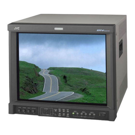
MULTI-FORMAT MONITOR
DT-V1910CG
DT-V1710CG
The illustration shows the DT-V1910CG with provided wide
mask attached.
©
2003 VICTOR COMPANY OF JAPAN, LIMITED
INSTRUCTIONS
UNDER
PULSE
COLOR
DEGAUSS
SCAN
CROSS
OFF
MUTING
SLOT 1
SLOT 2
A
B
C
D
INPUT SELECT
MENU
SCREENS
ASPECT
AREA
VOLUME
CHECK
MARKER
(DT-V1910CG shown)
POWER
SLOT 3
E
F
LCT1318-001A
0303-MA-CR-VP
Advertisement
Table of Contents

Related Manuals for JVC DT-V1710CG/E


Summary of Contents for JVC DT-V1710CG/E
- Page 1 MULTI-FORMAT MONITOR DT-V1910CG INSTRUCTIONS DT-V1710CG UNDER PULSE COLOR DEGAUSS SCAN CROSS POWER MUTING SLOT 1 SLOT 2 SLOT 3 The illustration shows the DT-V1910CG with provided wide INPUT SELECT MENU SCREENS ASPECT AREA VOLUME CHECK MARKER mask attached. (DT-V1910CG shown) LCT1318-001A 0303-MA-CR-VP ©...
-
Page 2: Safety Precautions
Thank you for purchasing this JVC Multi-Format Monitor. Before using it, read and follow all in- structions carefully to take full advantage of the monitor’s capabilities. SAFETY PRECAUTIONS In order to prevent any fatal accidents caused by misoperation WARNING or mishandling the monitor, be fully aware of all the following This is a class A product. -
Page 3: Table Of Contents
CONTENTS SAFETY PRECAUTIONS ................ 2 CONTROLS AND FEATURES ..............4 CONTROLS AND FEATURES (INPUT CARD: OPTIONAL) ..............7 PREPARATION ..................11 BASIC MENU OPERATIONS (MAIN MENU, SETUP MENU)............. 13 HOW TO USE “MAIN MENU”..............15 HOW TO USE “SETUP MENU” ............. 18 HOW TO USE EXTERNAL CONTROL.......... -
Page 4: Controls And Features
CONTROLS AND FEATURES FRONT VIEW <Front Panel> 11 12 13 14 19 20 UNDER PULSE COLOR MUTING DEGAUSS SCAN CROSS POWER SLOT 1 SLOT 2 SLOT 3 MENU SCREENS ASPECT AREA INPUT SELECT VOLUME CHECK MARKER UNDER PULSE COLOR MUTING DEGAUSS SCAN CROSS... - Page 5 12 UNDER SCAN button/lamp AREA MARKER button/lamp Press the UNDER SCAN button. The button This button turns the AREA MARKER function lights and the screen is reduced (under-scan) ON/OFF. and the whole screen is displayed. • AREA MARKER function includes MARKER, ZOOM, and SAFETY AREA functions.
-
Page 6: Rear Panel
CONTROLS AND FEATURES (cont'd) Power lamp POWER switch Unlit : The main power is OFF. Press the power switch to turn the monitor’s Orange : The main power is ON, but the monitor’s power power ON or OFF when the main power is ON. is OFF (in stand-by mode). -
Page 7: Controls And Features (Input Card: Optional)
CONTROLS AND FEATURES (INPUT CARD: OPTIONAL) COMPONENT/RGB INPUT CARD (IF-C01COMG) Component/RGB signal input/output terminals Input (IN) and output (OUT) terminals for component (colour difference) or RGB signals. Select component signal: INPUT SELECT A (SLOT1)/C (SLOT2)/E (SLOT3) /B-Y Select RGB signal : INPUT SELECT B (SLOT1)/D (SLOT2)/F (SLOT3) * The IN and OUT terminals are bridge-connected (auto termination). - Page 8 CONTROLS AND FEATURES (cont'd) (INPUT CARD: OPTIONAL) SDI INPUT CARD (IF-C01SDG) SWITCHED OUT terminal Output (OUT) terminal for the re-clocked signal. The input signal from SDI 1 or SDI 2 (selected with the INPUT SELECT buttons) is re-clocked and SWITCHED output from this terminal.
- Page 9 SDI INPUT CARD (IF-C21SDG/IF-C51SDG) Compliant with EMBEDDED AUDIO and AUTO INPUT (the SDI input card IF-C51SDG is equipped with an AUDIO LEVEL METER function) SWITCHED OUT terminal Output (OUT) terminal for the re-locked signal. The currently selected input signal is output from this terminal. SWITCHED NOTES: •...
- Page 10 HD SDI INPUT CARD (IF-C21HSDG/IF-C51HSDG) Compliant with EMBEDDED AUDIO and AUTO INPUT (the HD AD SDI input card IF-C51HSDG is equipped with the AUDIO LEVEL METER function) HD SDI signal input/output terminals (HD SDI1) Input (IN) and output (OUT) terminals for the HD SDI signal (HD component serial digital signal).
-
Page 11: Preparation
PREPARATION INSTALLING THE INPUT ATTACHING THE WIDE CARD MASK Optional input cards are necessary to use the functions of this A wide mask is provided with the monitor. This changes the monitor. Before mounting the monitor or connecting other viewable screen area to the 16:9 aspect ratio. equipment to the monitor, be sure to install the input cards. -
Page 12: Attaching The Power Cord Holder
PREPARATION (cont'd) ATTACHING THE POWER CORD HOLDER • The provided Power Cord Holder prevents accidental disconnection of the AC power cord from the AC inlet. • The Power Cord Holder consists of two parts; a case and cover. 1. Attach the Power Cord Holder case to the AC inlet on the back of the monitor with 2 screws (provided). -
Page 13: Basic Menu Operations (Main Menu, Setup Menu)
BASIC MENU OPERATIONS (MAIN MENU, SETUP MENU) ABOUT MENU SCREENS This monitor features a MAIN MENU (main menu screen) and a SETUP MENU (setup menu screen). The MAIN MENU contains the functions normally used, and the SETUP MENU contains the settings required for initial setup. “MAIN MENU”... -
Page 14: Displaying The Menu
BASIC MENU OPERATIONS (cont'd) (MAIN MENU, SETUP MENU) DISPLAYING THE MENU About “ sub menu” SCREENS Only displays selected items. (sub-menu display) Allows you to adjust and set items while looking at the actual screen. To display MAIN MENU Press the MENU button on the front panel. NOTE: To display SETUP MENU •... -
Page 15: How To Use "Main Menu
HOW TO USE “MAIN MENU” “MAIN MENU” SCREENS MAIN MENU Setting Items Press See page 16. Some items are not displayed depending on the picture input signal. ( See page 13.) Adjusts with buttons. See page 14 for more information on “... - Page 16 HOW TO USE “MAIN MENU” (cont'd) ITEM CONTENTS AND ADJUSTMENT RANGE/SETTINGS APERTURE CONTROL AREA MARKER: Compensates the frequency characteristics of the Controls ON/OFF and other settings of the MARKER, input video signal. SAFETY MARKER, and ZOOM functions included in the AREA MARKER function. Press the button to display the setting menu...
- Page 17 SAFETY AREA/R-SAFETY AREA R-Y PHASE Displays dotted lines to indicate the areas corre- Sets the R-Y phase. sponding to 80%, 88%, or 90% of the screen size • 90/92/94/112 (the aspect ratio setting in “ASPECT SELECT/R- ASPECT SELECT”). R/B GAIN Sets the R/B gain.
-
Page 18: How To Use "Setup Menu
HOW TO USE “SETUP MENU” “SETUP MENU” SCREENS Setting Items SETUP MENU Press See page 22. Adjusts with buttons. See page 14 for more information on “ sub menu” and “reset”. * To go back the previous MENU, press MENU. - Page 19 ITEM CONTENTS AND ADJUSTMENT RANGE/SETTINGS FUNCTION SETTING SYNC SELECT Synchronized signal selection. Selects the control systems for the COLOR SYSTEM, INT. : The input video signal is synchronized with the synchronized signal, RUSH DELAY TIME, tally lamp built-in sync signal. colours, and MAKE/TRIGGER terminal.
- Page 20 HOW TO USE “SETUP MENU” (cont'd) PICTURE SUB ADJ. COLOR TEMP./BAL. Controls the approximate adjustment of the video Sets or adjusts the colour temperature or white control level when the video adjustment knob is balance. adjusted to the centre. Press the button to display the setting menu •...
- Page 21 DISTORTION ADJ. SIZE/POSI. ADJ. Compensates the picture distortion. Adjusts the size or position of the picture. Press the button to Press the button to display the setting menu display the setting menu illustrated on the right. illustrated on the right. PINCUSHION H.SIZE Compensates pincushion picture distortion.
-
Page 22: Status Display
HOW TO USE “SETUP MENU” (cont'd) STATUS DISPLAY OVER LEVEL ( ) Sets the input level’s lower limit indicated in red for Sets the status display ON/OFF. the “3COLORS” display. * Switches the display on and off. Also selects the type of display. -
Page 23: How To Use External Control
HOW TO USE EXTERNAL CONTROL ABOUT EXTERNAL CONTROL The Multi-Format Monitor has two external control terminals. One is the MAKE/TRIGGER terminal, which allows the monitor to be controlled by the MAKE(make contact) or TRG. (trigger contact) method selected in the function setting. MAKE (make contact system): Controls functions either by short-circuiting (short with GND of 15th terminal) or stable disconnec- tion (terminal open) of the controlled terminal. - Page 24 HOW TO USE EXTERNAL CONTROL (cont'd) HOW TO USE THE RS-485 TERMINAL You can control the monitor from the controller (exclusive for this monitor) or your PC via the RS-485 terminal. For details on operating the monitor from the PC, consult the service centre. 1.
-
Page 25: Troubleshooting
TROUBLESHOOTING Solutions to common problems related to your monitor are described here. If none of the solutions presented here solve the problem, unplug the monitor and consult a JVC-authorised dealer or service centre for assistance. Reference Problems Points to be checked... - Page 26 TROUBLESHOOTING (cont'd) Reference Problems Points to be checked Measures (Remedy) pages Irregular colour Is the monitor placed or moved close to Move the device away from the monitor. a speaker or any other device Press the DEGAUSS button on the front panel to incorporating a magnet? degauss the screen.
-
Page 27: Self-Check Indications
SELF-CHECK INDICATIONS When the screen goes blank, and one or more of the INPUT SELECT A through F buttons on the front control panel start blinking... This monitor has a self-check function, which allows it to detect malfunctions and alert you. This makes trouble-shooting easier. Whenever a problem occurs, a combination of “self-check indicators”... -
Page 28: Specifications
SPECIFICATIONS Model DT-V1910CG DT-V1710CG Type Multi-Format Monitor Multi-Format Monitor Picture Tube 19" measured diagonally 17" measured diagonally Effective Screen Size Width :370 mm Width :330 mm Height :270 mm Height :250 mm Diagonal :460 mm Diagonal :410 mm H : 15 kHz/27 kHz – 45 kHz Scanning Frequency V : 50 Hz –... - Page 29 SPECIFICATIONS (cont’d) 7Dimensions [DT-V1910CG] Unit : mm <Front View with the wide mask attached> Asterisks(*) are used to indicate front panel dimensions. 372 * UNDER PULSE COLOR MUTING DEGAUSS SCAN CROSS SLOT 1 SLOT 2 SLOT 3 POWER INPUT SELECT VOLUME MENU SCREENS...
- Page 30 Compliant Signal Formats of Each Input Card Input Signals IF-C01PNG IF-C01CONG IF-C01SDG IF-C21SDG IF-C51SDG IF-C12HSDG IF-C21HSDG IF-C51HSDG NTSC (3.58 MHz) — — — — — — — PAL (4.43 MHz) — — — — — — — Black-and-White — — —...
- Page 31 SPECIFICATIONS (Input card : optional) Precautions when attaching an input card with dip switches Some input cards have two dip switch arrays: dip switch array S101 on the upper part of the connector terminal and dip switch array S102 on the lower part. The surface of these switches is pre-coated with a film on shipment from the factory. When problems arise, such as not being able to set functions properly with the dip switches, be sure to check the following: The numbers 1 to 16 on the PC board to the right of the Dip switch array S101...
- Page 32 VICTOR COMPANY OF JAPAN, LIMITED Registered Trademark owned by VICTOR COMPANY OF JAPAN, LTD.
- Page 33 !"# !" DT-V1910CG DT-V1710CG UNDER PULSE COLOR DEGAUSS SCAN CROSS POWER MUTING SLOT 1 SLOT 2 SLOT 3 INPUT SELECT MENU SCREENS ASPECT AREA VOLUME CHECK MARKER !"#$%&'() !"#- LCT1318-001A 0303-MA-CR-VP © 2003 VICTOR COMPANY OF JAPAN, LIMITED...
- Page 34 !" !"#$- !"#$%&'()*+,-./012$3456789:;< !"#$%&' !"#$%&"#'()*+,-./0123456 !"#$%&- !"# !"#$%&'()*+ !"#$- !"#$%&'()*+,- !"#$%&'()*+,-./0123#4 !"#$%&- !"#$%- !"#$%&'()*+- !"#$%- !"#$- !"#$%&'(- !"#$- !"#$%&'()*+,-.- !"#$- !"#$%&!"'()*+,-./012345 !"#$%&'(- !"#$%&'()*+,-#()./01234 !"#$%&' !"#$%&'($%)*+,-./012345 !"#$%&'()'*+,- !"#$%& !"#$%&'()"*- !"#$%&'( !"#$%&'() !"#$%&'()*+,-.%&+/01/- !"#$%&'()*+,$ -./012- !"#$%&'()*+%,-./0 1%234 !"#$%&'()*+,&-./0123)45 !"#$%- !"#$%&'()*+,-./0)*12345 !"#$%&'()*+%,-./012!- !"#$%&'()*+,-./0123 !"#$%&'()*+,-./0- !"#$%&'()*+,-./012-...
- Page 35 !"#$%&' !" !" !"#$% !"# !"#$ !% !" !"# !" !"#$ !"#$%...
- Page 36 !" 11 12 13 14 19 20 UNDER PULSE COLOR MUTING DEGAUSS SCAN CROSS POWER SLOT 1 SLOT 2 SLOT 3 MENU SCREENS ASPECT AREA INPUT SELECT VOLUME CHECK MARKER UNDER PULSE COLOR MUTING DEGAUSS SCAN CROSS SLOT 1 SLOT 2 SLOT 3 POWER VOLUME...
- Page 37 !"#$% !" !"#$%& !"#$%&' !"#$%&'(- !"#$%&' !"#$ !"#$ %& • • !" !"#$ !"#$%&'(- !"#$% !"#$%&- • !"#$%&'()*+,-. • !"#- !"#$% !"#$%&'- • !"#$%&$%'( !"#$%&'() !" • !"#$%&'( !"#- !"#$%&'(- !"#- !"#$% &'(- !"#$%&- • !"#$%& '()* %!+,-%./ • !"#$% !"#$%- •...
- Page 38 !" !"# !"- !"#$%& '( !"#$%&'( !"#$%&- !"#$%- !"#$%&' !"#$% !"#$%&' !"#$%&- !"#$%&'()%&*+,-./0123 REMOTE MAKE/TRIGGER G / Y SWITCHED RS-485 /B-Y HD SDI 1 /B-Y HD/C HD SDI 2 AUDIO AUDIO MAIN POWER !" !" !"#$ !"# !"#$%&'()*- !"#$- !"#$%&'(&) !"#$ !"#$%&...
- Page 39 !" !"#$ !"#$ !"# !" !"#$ !"# !"# /B-Y !" !"#$%&'()*& +,"-!- !"# /B-Y !"#$%&'()*+,- !" !"#$%&'( !"#$%&'( !"- • HD/C !"# !"#$%&- !"#$%& !"#$%&' !" !" !"#$%&'()*&- • AUDIO !" #$%&'()* !"#$%&'()#*+- !"#$ !"#$%& !"# !" !"#$%&'( VIDEO 1 !"...
- Page 40 !" !"#$ !"#$ !"# !"#$ !"#$%& !"' ()*+,-.%& SWITCHED !"#$ !"#$% !"#$%&'!" • !"#$%&'(- SDI 1 !"#$%&'()*&'+, !"#$%&!"'( • !"#$ SDI 2 !"#$ !"# AUDIO 1 !"# AUDIO 2 !"#- !"# !"#$ !"#$%&' !" !"#$ !" !"#$%&'#- • !" #$%&'()* !"#$%&'()#*+- !"#$ !"#...
- Page 41 !"#$ !" !"#$%&$ !"#$% !"#$% !"#$%&'()*#+- SWITCHED !"# !"#$%& !"#$%&!"'! • !"#$% &'- !"#$%&'()*+, !"#$%&!"'(- • E.AUDIO !"#$%&'() !"#$%& !" !"#$% !"#$%& !"#"$%&'()*+,-.- !"#"$%&'()- AUDIO !"# MONITOR !"# !"# !"#$ !"#$% !"#$%&'()*- !"# !"#$%&'()*+,#!-.%/01- !"#$%"#&'()"*+$,-./0%"#123456&/0%1 • !"#$%&'()*+,-./0123450167- • !" #$%&'()*+%,-.- !"#$%&'()*+,-- •...
- Page 42 !"#$ !"# !" !" !" !"#- !" !"#$% !"#$%& E.AUDIO HD SDI 1 !"#"$%&'()*+,-.- !"#"$%&'()- !"# !"# !"#$%& !"#$%&'()*+,-. !"#$% &'- • !"# !"#$% !"#$%&'()*- AUDIO MONITOR !"#$%&'()*+,#!-.%/01- !" #$%&'()*+%,-.- !"#$ !"#$%&'()*+,-- • !"#$%&'() !"# !"# !"#$%&'() !"#$%&'(-...
- Page 43 !" !"# !"#$%&'()*- !"#$%&'()* !"#$%&'()- !"#$%&'()*+ !"#$%&'()*+,-./- !"#$%&'(")*+,- !"#$%& • !"#$%&'()* !"# !"#$- !"#"$ - !" #$%&'()(*+,-. !"#$%&- !"#$% !"#- !"#$%&'() - REMOTE MAKE/TRIGGER RS-485 !"#$%& !"#$%&' '()*+,-! !"#$%&' - !"# !"#$ !"# - REMOTE MAKE/TRIGGER RS-485 !" !"#$%&'()*+,-.&/ !"#$ !"#$%&' - !"# !"#$%&'()
- Page 44 !"#$% !"#$%&'()*+,-./0$&123./$%45678- • !"#$% !"#$%- • !"#$%& !"#$%&'()*+,-./0123- !"#$%&'()*+ !,- !"#$%&'- !"#$%&'()*+- !"#$% "&'%()* "&#+,-./0+,-1- !"#$%&'()*- !"#$%&'($)*+,-./0- !"#$%&'($)!*+- • !"#$%&'()*+,-./012345- •...
- Page 45 !"# !"# !"# !"#$ !" !#$"% !"# !"$%#- • !"#$%&'()* !"#$%&' • !"# !"# !"#$%&#'() !" !"#$%&'(#$%)* !"#$ !"#$%&'()*+,- !"# !" !"# ! " !"# $ !"# !"# !"#$%&'( !" !"# - !"#$%&' !"# - !"#$%&'()*+,- !"#$% - !"#$%&'( )*+,-. - !"...
- Page 46 !"# !"# !"# • !"# !"#- !"#$- !"#$%&'() • !"#$%&'(- !"#$ !" !"#$%&'( !"#$%&- • !"#$%&'() • !"#$%& !"#$ % !"#$%&'( • !"#$%&'(- !"#$%&' !"#- • !"# !"# !"#$ !" !"# !"#$%&'( !"#$%- !"#$% !"# !"#$ !"#- !"#$%&'()' !"#$%&'()*- !"#$%&'(- !"# !"# •...
- Page 47 !" !" !"#$% !"#$%&'()*+ ,- !" !" !"#...
- Page 48 !" !" !"#$%&'() !"# !"# !"#$%&#'()- !" !"#$%&' !" !"#$% !"#$ !"#$ !"#$- !"#$% !"#$- !"#"$%& !"$%- • !"# !"#$%& !"#$ • !"- !"#- !"# !"#$%&'( • !" !"#$%&'()- !" !"#$ !"#$%&' • !"# !"#$ !"# • !"#$%&'(- !"#$%&'() !" !"#$% !"#$%&...
- Page 49 !" !" !"#$%&'( • !"#$ !"#$%&'- • !" !" !" • !"#$%&'() • !"#$%&'( !" • !" • !"#$ !"# R-Y PHASE R/B GAIN 0.79 !"# ITU601 G-Y PHASE !"#$%&'(#)*+- G/B GAIN 0.45 !"#$% R-Y PHASE !"#$- R/B GAIN 0.86 ITU709 G-Y PHASE G/B GAIN...
- Page 50 !" !" !" !" !"# !"# •...
- Page 51 !"#$%&'() !"# !"#$%&'(- !"# !"#$%&'()*+,-./"#0 !"#$%&'()*+ !"#$%&'!"#$()*+,*+ !"#$%&'() !"#$%&- !"#$%- !"# !"#$%&'(- • !" #$%&'(!)*+,-!./0! !"#$%& • !"#$%&'!"()#- !"#$% !"- !"#$!""%& '( • !"#$% !"- !"#$%&- !"#$%&!'()*+- !"#$%&'()*+,-.$/01 2%&34'( !" !"#$%&'()*+,-- !"# !"#$%&'()*+,-./- !"#$%&- !"#$%&- !"# !"#$%- !"# !"#$ !"#$% !"# !"#$%&'()*+,- •...
- Page 52 !" !"#$ !" !"#$!%&'()*+,- !./0 !"#$$%&'$()- !"#$% !"# !"#$%&'()*+- !"#$- • !"#$% !" #$ !" • !"#$%&- !"#$- !"#$%& !"# !"- !"#$ !" !" !"# !"# • – !" !"#$ !"#$%&- • – ! " • !"#$ • – !"#$%&- ! "...
- Page 53 !"# !"#$ !"#$%&- !"#$- !"#$% !"#$% !"#$- !"#$- !"# !"#$%- !"#$%- • – • – !"#$%- !"#$%- – – !"#$%- !"#$%- !"#$%&' !" !"# !"#$%&'()*- !"#$%- • – • – !"# – !"#- !"# – !"#- !"# !"# !"#$%&'- !"#$%- •...
- Page 54 !" !"# !"# !"#$%&'() *# !"#$ !"#- !" !"#$%- • – – – – • !"#$%&'()* !"#$%&'( !"#$%& '() • !"#$%&'( !"- !"#$% !"#$- !" !" !"#$ !" !"#$%&'() !"# !"# !"- !"#$ !"#$%&'() 1 2 3 4 5 6 7 8 •...
- Page 55 !"#$% !"# !"#$% !"#$- !" !" !"#$% !" !"#$%& !" !"#$ !"#$%&'()*& +,()-./0+,- !" !"#$%&'()*+,-.'/ !"#$%&- !"# !"#$!" !" !"#$%&'($) !"#$%&'( )*+,-.(/0- !"#$ !"- !"#$%&'()*+,-./0123- !" 5 4 3 2 1 13 12 11 !" !" !" !" !" !" !"...
- Page 56 !"#$% !"#$%&'#()*!"&'#+, !"#$%&- !"#$%&'()*+,-./01 !"#$%&- !" !"#$%& !"#$% !"- !"# !"#$ !"#$%&'() !" !" !" !"#$% !"#$%& !"#$%& !"#$% !"#$%&' ()%- !"#$% !"#$% !"#$% !"#$% !"#$% !"#$%& !"#$- !"#!$%& !"#$% !"# !"#$%&' !"#$% !"#$%&'()*+,-- !"#$ !"#$% ! "#$- !"#$%&'()*+,-./0123456789:,-.;<=>?@ !"#$%&'()*- !"#$%&'()*+,-.!/012)3...
- Page 57 !"#$%&'(!)*+,-. - !"#$%&'()* !"#$% !"#$%&'()* !"#$% !"#"$%&'#"()* !"# $- — !"#$% !" !"#$ !"#$%& !"#"$%&' !"#$%- 7~10 !"#$%$ !" !"#$%& — !"#"$%&'( !"#$%&'( !"#$%!"&'( !"#$%&'()*+ !"#$%&'()*+,- !.$%- 7~10 !"#$%&' !" !"#$%&'()- !"#"$%&' !"#$%- 7~10 !"#"$%&'()* !"#$%- — !"#"$%&'() !"#$%!"&'( !"#"$%&' !"#$%&'()*+,-./0(- !"...
- Page 58 !"#$% !" !"!#$%&'()%*+, !"#$%&'- !"# !"# !"#$%& !"#$%&'()*+, !"#$%&'° C !"#$ !" !"#$#%& !" !" !"#$% !"#$ !" !"#$ !" !"#$% !" !"#$% !" !"#$%&'() !"#$% !"#$%&- !"# !"#$ !"#$ !" ! "#$%&- !"#$%& !"#$%&' !"#$%&'( !" !"#$#%&'()*+,- !"#$%&'() "*+,-- 23, 24 !"#$%&...
- Page 59 !"# !"#$%&'()*+ !"#$%&' !"#$%&'()*+,-./012- !"#$%&'(- !"# !"# !"#$%#&'()*+,-./01234- !"#$%&'()*+,-.&/012345678 SLOT 1 SLOT 2 SLOT 3 INPUT SELECT UNDER PULSE COLOR MUTING DEGAUSS SCAN CROSS SLOT 1 SLOT 2 SLOT 3 POWER MENU SCREENS ASPECT AREA INPUT SELECT VOLUME CHECK MARKER !"...
- Page 60 !"# !"# !"# — — !" !"#$%& !"# !"# !"# !"# !"#$ !"#$ !" !" !" !" !" !" !" !"#$%&'()* !"#$%&'()* !"#$%&'()* !"#$%&'()* ! " !"# !" !"#$% !" !"# !"#$%$&'()*+,-./0+1234567- !"#$%&'()*+- !"#$%&- !"#$%&'()*+,-...
- Page 61 [DT-V1910CG] !"#$%&'( !"#$%&'()- 372 * UNDER PULSE COLOR MUTING DEGAUSS SCAN CROSS SLOT 1 SLOT 2 SLOT 3 POWER INPUT SELECT VOLUME MENU SCREENS ASPECT AREA CHECK MARKER 377 * UNDER PULSE COLOR MUTING DEGAUSS SCAN CROSS POWER SLOT 1 SLOT 2 SLOT 3 MENU...
- Page 62 !"#$%&'() IF-C01PNG IF-C01COMG IF-C01SDG IF-C21SDG IF-C51SDG IF-C12HSDG IF-C21HSDG IF-C51HSDG NTSC (3.58 MHz) — — — — — — — PAL (4.43 MHz) — — — — — — — (50 Hz/60 Hz) — — — — — — — 480/60i (525i) —...
- Page 63 !"#$%&' !"#$%&'()* !"#$%&'()*+,-./012 ! "#$%& !" !"#$%&'()*+,-./01234- !"#$%&'()*+, !"#$%&'()*+,-./01- !"# !"#$%&'() !" !"#$ !"#- !" #$%& • !"#$% !" #$%& !"- !"#$%&'( !" • !" !"#$%&'( !"#$%&'() * !" !"#...
- Page 64 VICTOR COMPANY OF JAPAN, LIMITED...