Table of Contents
Advertisement
Quick Links
Download this manual
See also:
Operating Manual
Advertisement
Table of Contents

Summary of Contents for Rinnai RINV25R-A
- Page 1 • Manufacturer’s Installation Instructions • Current AS/NZS 3000 •All applicable local rules and regulations including local OH&S requirements This system must be installed, commissioned and serviced by an Authorised Person.
-
Page 2: Table Of Contents
CONTENTS Safety Precautions WEEE Warning Name Of Each Part Operation Notices Care and Maintenance Troubleshooting Installation Guide Selection of installation location Installation of the indoor unit Installation of the outdoor unit Pipe connection Electrical connection Commissioning Packing list... -
Page 3: Safety Precautions
Safety Precautions Incorrect operation due to ignoring instruction will cause harm or damage. The seriousness is classified by the following indications: WARNING This symbol indicates the possibility of death or serious injury. CAUTION This symbol indicates the possibility of injury or damage to properties only. WARNING The air conditioner must be earthed. -
Page 4: Weee Warning
CAUTION 1.Don t install the indoor unit in direct sunlight. 2.Don t block air inlet or air outlet, otherwise, the cooling or heating capacity will be weakened, even cause system stop operating. 3.Don’t apply cold air to the body for a long time. It will deteriorate your physical conditions and cause health problems. -
Page 5: Name Of Each Part
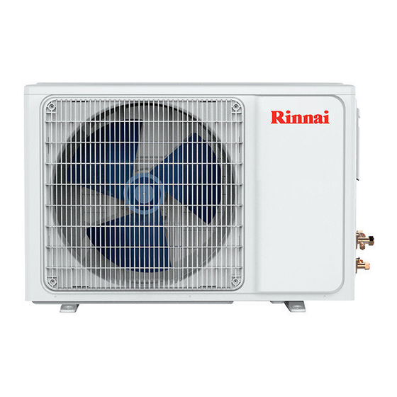
Name of Each Part ★ Indoor Unit Air inlet Indoor Unit 1、Front panel 2、Air filter 3、On/Off button 4、Louver Air outlet 5、Signal receiver 6、Supply cord (if installed) 7、Remote controller 8、Drain hose 9、Refrigerant gas/ ★ Outdoor Unit liquid pipe Air inlet Outdoor Unit 10、Cut-off valve 11、Air outlet cover Air outlet... -
Page 6: Operation
Operation ★ Remote controller operation See "air conditioner remote controller instruction " ★ Manual operation ☆ Manual operation When the remote controller does not work or can not be found, please follow these steps: ☆ Adjusting air flow direction Adjusting h orizontal air flow manually. -
Page 7: Notices
Notices To prevent injury and property damage, Please pay attention to these following before operating the air conditioner. ★ Checking before operation 1.Make sure that the earth wire is connected safely and reliably. 2. Make sure the filter net is properly fixed. 3. -
Page 8: Care And Maintenance
Care and Maintenance ★ Cleaning ☆ Cleaning the indoor unit 1.Turn off the air-conditioner and remove the electrical plug from the outlet. Wipe the indoor unit with a moist (not dripping wet) cloth using warm mildly soapy water. ! Note : Don t use water above 45℃... - Page 9 Troubleshooting Phenomenon Is the remote controller out of effective distance to the indoor unit? Remote controller is not working Is the battery flat? Are there any obstructions between the controller and the signal receptor? Is the setting temperature suitable? Is the air inlet or outlet obstructed? Cooling (Heating)efficiency is not Is air filter dirty? good...
-
Page 10: Installation Guide
Installation Guide ★ Guide for customer 1.Please read the instructions carefully before installation of the air-conditioner. 2.The installation should be carried out by only authorised persons. 3.Installation the air-conditioner and connecting the pipes and wires must strictly follow the instructions 4.The wiring must be done by qualified electrician according to the electrical safety requirements. -
Page 11: Selection Of Installation Location
Selection of the installing position ★ Indoor Unit ● There is no heating and Above steaming source nearby. 15cm ● No obstacles for installing position neatly. ● Keep good air circulation. ● Convenient to adopt 15cm Above measures to reduce noises. ●... -
Page 12: Installation Of The Indoor Unit
Installation of the indoor unit ●First make changes to wall and make sure that is hard and secure. Using four + type screws to fasten the " " installation board onto the wall. Use a spirit level to ensure both horizontal and vertical level to ensure proper operation and drainage of condensate tray and drain line. -
Page 13: Installation Of The Outdoor Unit
★ Check the water discharge 1. Take off the frame the unit cover. Take off the front frame for maintenance according to the following steps: ● Turn perpendicular airflow direction handle from I to horizontal direction. " " ● As shown in the picture on the right, take off Bolt Bolt Vertical airflow two covers from the front frame and then... -
Page 14: Pipe Connection
Pipe connection ● Connect the pipe to the unit: point to the center of pipe and fasten by wrench until it is tightly The size of pipe Torque fastened, the fastening 6.35mm( 18N.m Pipe torque is in the Indoor unit Connection screw following picture. -
Page 15: Expelling The Air In The Pipes And The Indoor Unit
★ Expelling the air in the pipes and the indoor unit Expelling the air: humid air in the Outdoor unit refrigerating system might cause trouble of compressor. ● Take off the cover from the stop valve and T-branch valve. ● Take off the auxiliary cover from the T-branch valve. -
Page 16: Electrical Connection
Electrical connection The connection cables should obey MDL this table: ≤9000Btu ≤12000Btu ≤18000Btu ≤24000Btu model (≤2500W) (≤3500W) (≤5100W) (≤7200W) Specification of connection cables (mm ) ★ Indoor connection Open the front panel, inset the connection cables from the base of the air-conditioner, conneting to the terminal board in order (according to the graph), using the pressing board to fasten the connection cables. - Page 17 Wiring diagram of constant speed Cover ≤5.2KW ≥7.0KW Terminal board Terminal board Grounded wire Grounded wire Electric bracket Electric bracket Pressing board Pressing board Cover Wiring diagram of variable speed Terminal board Terminal board Grounded wire Electric bracket Electric bracket Pressing board Pressing board NOTE:...
-
Page 18: Commissioning
Test running ● Make sure that pipes and wires are connected. ● Make sure that liquid side valve and air side valve both are completely open. 1. The connection of power source ● Connect the wire to independent power source socket. ●...


