Table of Contents
Advertisement
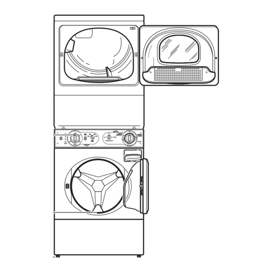
Installation Instructions
for Stacked Washers and Dryers
Inside
..........................................................
Dimensions........................................................................
Before You Start................................................................
Installation.........................................................................
Installer Checklist ........................................... Back Cover
Date Purchased _____________________________
Model Number _____________________________
Serial Number _____________________________
Keep these instructions for future reference.
(If this machine changes ownership, this manual must accompany machine.)
www.speedqueen.com
3
4
5
Part No. 802714R5
July 2013
Advertisement
Table of Contents

Related Manuals for Speed Queen Stacked Washers and Dryers


Summary of Contents for Speed Queen Stacked Washers and Dryers
-
Page 1: Installation Instructions
Installation Instructions for Stacked Washers and Dryers Inside ............Dimensions................ Before You Start..............Installation................. Installer Checklist ........... Back Cover Date Purchased _____________________________ Model Number _____________________________ Serial Number _____________________________ Keep these instructions for future reference. (If this machine changes ownership, this manual must accompany machine.) Part No. - Page 2 WARNING FOR YOUR SAFETY, the information in this manual must be followed to minimize the risk of fire or explosion or to prevent property damage, personal injury or death. W033 • Do not store or use gasoline or other flammable vapors and liquids in the vicinity of this or any other appliance.
- Page 3 Dimensions 23.5 in. (59.7 cm) 8.0 in. (20.3 cm) 15.4 in. (39.1 cm) 5.25 in. (13.3 cm) 24 in. (61 cm) *13.1 in. (33.3 cm) 26.875 in. 28 in. *14.6 in. (71.1 cm) (68.3 cm) (37.08 cm) 2.0 in. 1.5 in. (5.1 cm) (3.8 cm) ELECTRIC DRYERS...
-
Page 4: Before You Start
Before You Start Parts Included An accessories bag has been shipped inside your unit. Supplies It includes: For most installations, the basic supplies you will need • Installation Instructions are: • Two User’s Guide (one for washer and one for dryer) •... - Page 5 Speed Queen will not cover scheduled repair services where the installation requirements are not per specifications, nor can products be returned to the authorized dealer in these cases.
- Page 6 Step 2: Position and Level the Unit Position unit so it has sufficient clearance for installation and servicing. Refer to Figure 2. SWD795N Dryer and Exhaust Duct Clearances Area Description Minimum Clearance Left Dryer Side 0 in. (0 cm) Right Dryer Side 1 in.
- Page 7 Place a level on the cabinet top and check if the unit is level from side to side and front to back. NOTE: Level must rest on raised portion of top panel. Refer to Figure 3. SWD832N Wood Block SWD833N Figure 4 Level Make sure that the unit does not rock.
- Page 8 Step 3: Connect Fill Hoses Water pressure must be a minimum of 20 to a maximum of 120 pounds per square inch (138 to 827 kPa) static pressure measured at the faucet. WARNING NOTE: Water pressure under 20 pounds per Under certain conditions, hydrogen gas square inch (138 kPa) will cause an extended fill may be produced in a hot water system...
- Page 9 IMPORTANT: Turn off water supply faucets after check-out and demonstration. Owner should turn off water supply whenever there will be an COLD extended period of non-use. NOTE: Longer fill hoses are available (as optional equipment at extra cost) if the hoses supplied with the washer are not long enough for the installation.
-
Page 10: Standpipe Installation
Step 4: Connect Drain Hose to Drain Receptacle Remove the drain hose from its shipping position on the rear of the washer by unhooking the hose from the retainer clamp and by removing the shipping tape. Install the drain hose into the drain receptacle (standpipe, wall or laundry tub) following the instructions below. - Page 11 Laundry Tub Installation: Step 5: (Gas Dryer Only) Connect Gas Supply Pipe For this type of installation, the drain hose MUST be secured to the stationary tub to prevent hose from WARNING dislodging during use. Refer to Figure 10. Use the beaded strap (supplied in accessories bag) to secure hose.
- Page 12 10. Tighten all connections securely. Turn on gas and Natural Gas Altitude Adjustments check all pipe connections (internal & external) Altitude Orifice Size for gas leaks with a non-corrosive leak detection Part fluid. feet inches 3000 0.0890 2.26 503778 NOTE: The dryer and its appliance main gas valve 6000 1830 0.0860...
- Page 13 Step 6: (Electric Dryer Only) Connect Grounding Information Electrical Plug • This dryer must be connected to a grounded metal, permanent wiring system; or an Dryer requires 120/240 Volt or 120/208 Volt, 60 Hertz, equipment-grounding conductor must be run 3 or 4 wire electrical supply. Refer to serial plate for with the circuit conductors and connected to the specific electrical requirements.
- Page 14 Connecting Power Cord with Three-Wire Plug NOTE: Four-wire cord is required for mobile homes or where codes do not permit grounding through neutral. NOTE: The power cord is NOT supplied with the electric dryer. Type of power cord and gauge of wire must conform to local codes and instructions.
- Page 15 Connecting Power Cord with Four-Wire Plug 4. Use the three screws from the accessories bag to attach the power cord wires to the terminal block. NOTE: Four-wire cord is required for mobile Refer to Figure 15. homes or where codes do not permit grounding through neutral.
- Page 16 3. Remove ground screw from ground to neutral 5. Attach power cord ground (green) wire to rear wire and save for use in Step 5. Ground to neutral bulkhead using ground screw removed in Step 3. wire will be attached to the neutral terminal in Step 6.
- Page 17 Step 7: Connect Dryer Exhaust System • Locate dryer so exhaust duct is as short as possible. WARNING • Be certain old ducts are cleaned before installing your new dryer. To reduce the risk of fire and combustion • Use 4 inch (102 mm) diameter rigid or flexible gas accumulation the dryer MUST be metal duct.
- Page 18 Exhaust Direction Exhaust System The dryer can be exhausted to the outdoors through the For best drying results, recommended maximum back, left, right or bottom of the dryer. EXCEPTION: length of exhaust system is shown in Table 4. Gas dryers cannot be vented out the left side To prevent backdraft when dryer is not in operation, because of the burner housing.
- Page 19 Step 8: Remove the Shock Sleeves and 4. Replace panel. Shipping Brace 1. Remove panel. FLW2272N FLW2272N Figure 25 FLW2269N FLW2269N Figure 22 2. Remove brace. Five bolts secure brace to machine. For easier removal, remove in order shown. FLW2268N FLW2268N Figure 26 IMPORTANT: The shipping brace, bolts,...
- Page 20 Step 9: Wipe Out Inside of Washer Drum Step 10: Plug In the Washer and Dryer and Dryer Drum Electric Dryer Before using the washer and dryer for the first time, Connect the dryer to an electrical power source. Refer use an all-purpose cleaner, or a detergent and water to Step 4 for information on connecting power cord.
- Page 21 The dryer is designed to be operated on a separate WARNING branch, polarized, three-wire, effectively grounded, 120 Volt, 60 Hertz, AC (alternating current) circuit protected by a 15 Ampere fuse, equivalent fusetron or To reduce the risk of an electric shock or circuit breaker.
- Page 22 Washer When plugging in the washer: • DO NOT overload circuits. Washer requires 120 Volt, 60 Hertz electrical supply and comes equipped with a 3-prong grounding plug. • DO NOT use an extension cord. Refer to serial plate for specific electrical •...
- Page 23 Grounding Information Step 11: Recheck steps 1-10 The washer must be grounded. In the event of Refer to Installer Checklist on the back cover of this malfunction or breakdown, grounding will reduce the manual and make sure that unit is installed correctly. risk of electric shock by providing a path of least Run the washer with a test load to make sure it is resistance for electric current.
- Page 24 After the dryer has operated for approximately five WARNING minutes, observe burner flame through lower front panel. Adjust the air shutter to obtain a soft, uniform blue flame. (A lazy, yellow-tipped flame indicates lack For personal safety, lower front panel must of air.
-
Page 26: Installer Checklist
Installer Checklist Fast Track for Installing the Unit (Refer to the manual for more detailed information) • Position Unit Near Installation Area. • Connect Dryer Exhaust System. CHECK • Position and CHECK Level the Unit. SWD449N SWD449N Washer Only • Remove the Shock Sleeves and CHECK Shipping Brace.