Table of Contents
Advertisement
Security and Remote Start
Model 5601
Installation Guide
This product is intended for installation by a professional
installer only! Attempts to install this product by a person other than a
trained professional may result in severe damage to a vehicle's electrical
system and components.
© 2008 Directed Electronics, Vista, CA
N5102V 2008-06
Advertisement
Table of Contents

Related Manuals for Viper 5601


Summary of Contents for Viper 5601
- Page 1 Security and Remote Start Model 5601 Installation Guide This product is intended for installation by a professional installer only! Attempts to install this product by a person other than a trained professional may result in severe damage to a vehicle’s electrical system and components.
- Page 2 Bitwriter®, Code Hopping™, Doubleguard®, ESP™, FailSafe®, Ghost Switch™, Learn Routine™, Nite-Lite®, Nuisance Prevention® Circuitry, Reveng- er®, Silent Mode™, Soft Chirp®, Stinger®, Valet®, Vehicle Recovery System®, VRS®, and Warn Away® are all Trademarks or Registered Trademarks of Di- rected Electronics. The Bitwriter (p/n 998U) ®...
-
Page 3: Table Of Contents
Contents Warning! safety first ..................5 What is included ....................7 Installation points to remember ................7 Virtual Tach ....................7 D2D ......................8 The control center ..................8 Valet® program switch ................8 Status LED ....................9 Doubleguard shock sensor .................9 Before beginning the installation ..............9 After the installation ..................9 Component locations and finding wires .............10 Making your wiring connections ...............10 Primary harness (H1), 12-pin connector .............11... - Page 4 Menu 1 - Security..................40 Menu 2 - Convenience ................41 Menu 3 - Remote start ................42 Feature descriptions ..................43 Menu 1 - Security..................43 Menu 2 - Convenience ................46 Menu 3 - Remote start ................48 Bitwriter® ....................52 Long term event history ..................54 Table of zones ....................55 Shutdown diagnostics ..................55 Remote starting diagnostics ................56...
-
Page 5: Warning! Safety First
Warning! safety first The following safety warnings must be observed at all times: • Due to the complexity of this system, installation of this product must only be performed by an authorized Directed Electronics dealer. • When properly installed, this system can start the vehicle via a command signal from the remote control. - Page 6 tion immediately and consult with the user to fix the problem immediately. After the remote start module has been installed, test the remote start module in accordance with the Safety Check outlined in this installation guide. If the vehicle starts when performing the Neutral Safety Shutdown Circuit test, the remote start unit has not been properly installed.
-
Page 7: What Is Included
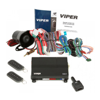
What is included • 2 Remote Controls (p/n 7153V) • The control module • Control center with integrated status LED and Valet Override switch (p/n 6111T) • Revenger™ Soft Chirp™ six-tone programmable siren • A remote start defeat toggle switch Installation points to remember This product is designed for fuel-injected, automatic transmission, or vehicles with manual transmissions. -
Page 8: D2D
➤ D2D The system has the ability to interface with an XK module through the D2D port. The advantage to using a D2D interface is that there is less wiring involved in the installation. Check the XK module installation guide to determine which wires are not needed, and which options are available. -
Page 9: Status Led
➤ Status LED The status LED is built into the control center. An optional LED (p/n 8634) is available if the onboard LED is not used for the install. The LED fits into a 9/32-inch hole. ➤ Doubleguard shock sensor Since the shock sensor is built into the main unit, be sure to keep the shock sensor performance in mind when deciding on a location for the main unit. -
Page 10: Component Locations And Finding Wires
in the owners guide. • Review and complete the Safety Check section of this guide prior to the vehicle reassembly. Component locations and finding wires For detailed information on where to locate components, and how to find the www.directechs. wires you need, please refer to the Direct Tech web site at com. -
Page 11: Primary Harness (H1), 12-Pin Connector
➤ Primary harness (H1), 12-pin connector H1/1 RED/WHITE (-) 200mA TRUNK RELEASE OUTPUT H1/2 (+)12v CONSTANT INPUT H1/3 BROWN (+) SIREN OUTPUT H1/4 WHITE/BROWN LIGHT FLASH ISOLATION WIRE - PIN 87a of onboard relay H1/5 BLACK (-) CHASSIS GROUND H1/6 VIOLET (+) DOOR TRIGGER INPUT H1/7... -
Page 12: Heavy Gauge Remote Start, (H3) 10-Pin Connector
➤ Heavy gauge remote start, (H3) 10-pin connector H3/1 PINK (+) IGNITION 1 INPUT/OUTPUT H3/2 RED/WHITE (+) FUSED (30A) IGNITION 2 / FLEX RELAY INPUT 87 H3/3 ORANGE ACCESSORY OUTPUT H3/4 VIOLET (+) STARTER OUTPUT (CAR SIDE OF THE STARTER KILL) H3/5 GREEN (+) STARTER INPUT (KEY SIDE OF THE STARTER KILL WIRE) -
Page 13: Door Lock Harness, 3-Pin Connector
wires directly to the vehicle you must place a 1-amp diode in line to prevent feedback from the vehicle. ➤ Door lock harness, 3-pin connector BLUE (+) LOCK (-) UNLOCK OUTPUT EMPTY NOT USED GREEN (-) LOCK (+) UNLOCK OUTPUT ©... -
Page 14: Wire Connection Guides
Wire connection guides ➤ Primary harness (H1) H1/1 RED/WHITE (-) 200mA TRUNK RELEASE OUTPUT When the system receives the code controlling trunk release output for longer than 1.5 seconds, the red/white wire supplies an output as long as the transmis- sion continues. - Page 15 H1/4 WHITE/BROWN LIGHT FLASH -ISOLATION WIRE - PIN 87a of onboard relay This wire connects to pin 87a of the onboard light flash relay. It is used when- ever light switch isolation on the vehicle is necessary. If the vehicle has a mul- tiplex circuit that needs the light switch isolated, you can remove the onboard light flash fuse and replace it with the specified resistor (paying attention to the polarity selection).
- Page 16 H1/6 VIOLET (+) DOOR TRIGGER INPUT This wire is used in vehicles that have a positive (+) switched dome light circuit. Connect the violet wire to a wire that shows (+)12V when any door is opened, and ground when the door is closed. H1/7 BLUE TRUNK PIN / INSTANT TRIGGER INPUT...
- Page 17 directly to the dome light circuit, as the output cannot support the current draw of one or more light bulbs. H1/10 WHITE/BLUE (-) REMOTE START/ TURBO TIMER ACTIVATION INPUT This input comes from the factory set to 1 activation pulse. This means that it is necessary to have a single ground pulse on the white/blue wire for the remote start to activate or to deactivate.
-
Page 18: Auxiliary Harness (H2)
(+) Positive Light Flash Output WHITE H1/11 (+) LIGHT FLASH OUTPUT (-) Negative Light Flash Output WHITE H1/11 (-) LIGHT FLASH OUTPUT Note: For parking light circuits that draw 10-amps or more, the internal jumper must be switched to a (-) light flash output. (See Setting the light flash polarity section of this guide.) P/N 8617 or a standard automotive SPDT relay must be used on the H1/11 light flash output harness wire. - Page 19 Relay for Negative (-) Disarm Wire Relay for Positive (+) Disarm Wire H2/2 LIGHT GREEN/WHITE (-) 200mA FACTORY ALARM ARM OUTPUT This wire sends a negative pulse every time the remote start shuts down or when the doors are locked with the remote. This can be used to pulse the arm wire of the vehicle’s factory anti-theft device.
- Page 20 H2/5 WHITE/BLACK (-) 200mA AUX 3 OUTPUT This wire provides 200 mA programmable output whenever the transmitter button(s) controlling Aux 3 is pressed. This output can be programmed to provide the following types of outputs • Validity: Output that sends a signal as long as the transmission is re- ceived.
- Page 21 WAIT-TO-START bulb in the dashboard. In most diesels the wire is negative (ground turns on the bulb) and the GRAY/BLACK wire can be directly connected to the wire in the vehicle. If the vehicle uses a positive wire (12V to turn on the bulb) a relay must be used to change the polarity.
-
Page 22: Heavy Gauge, 10-Pin Connector
to be used like a siren output with arm/disarm honks. Refer to System Features Menu#1, Feature 10, for more information. ➤ Heavy Gauge, 10-pin connector There are 9 heavy gauge wires coming from the large 10-pin connector. They are used to energize the ignition circuits in the vehicle. It is crucial to ensure that these connections are capable of handling the current demands. -
Page 23: Remote Start Input - 5-Pin Connector
H3/7 PINK/WHITE (+) IGNITION 2 FLEX RELAY OUTPUT This wire is factory programmed as Ignition 2 and can be programmed as a 2nd accessory for 2nd starter. H3/8 PINK/BLACK 87a OF IGNITION 2 FLEX RELAY This wire is used when an ignition switch isolation on the vehicle is necessary This is common on Toyota and Nissan's which require the use of Tech Tip docu- ment #1077. - Page 24 VIOLET/WHITE TACHOMETER INPUT WIRE This input provides the module with information about the engine’s revolutions per minute (RPMs). It can be connected to the uncommon colored wire of the fuel injector, the crankshaft position sensor, the camshaft position sensor or the negative side of the coil in vehicles with conventional coils.
- Page 25 ➤ Remote start auxiliary output, 5-pin These signals are provided to drive additional optional relays. PINK/WHITE (-) 200mA FLEX RELAY CONTROL OUTPUT This wire is programmed as (-) 2nd ignition output from factory and can be pro- grammed (to drive a relay) as a (-) starter or an accessory output. ORANGE (-) 200mA ACCESSORY OUTPUT This wire works like the main accessory wire and can be used (with a relay) to...
-
Page 26: Door Lock Wire Diagrams
➤ Door lock wire diagrams Important: Depending on the vehicle, the door locks may be con- trolled by an optional data bus expansion module. If so, no door lock interface wiring is required. There are eight different types of door lock systems (Type A - H). The more common type of door lock systems are Type A or Type B. -
Page 27: Neutral Safety Switch Interface
Neutral safety switch interface Some vehicles do not have an electrical neutral safety switch. Instead, the ve- hicle has a mechanical neutral safety switch that physically interrupts the starter wire and is used when the vehicle is in any drive gear. If the remote start is interfaced before this switch, it will provide protection from starting in gear. -
Page 28: Plug-In Led And Valet/Program Switch
Plug-in LED and valet/program switch The LED and valet switch are incorporated into the control center, the LED line plugs into the white 2-pin port and the Valet switch line plugs into the blue 2-pin port. Note: Onboard LED and valet switch can be substituted with an optional out- board LED (P/N 8634 for Blue LED and 8633 for red LED) and an outboard valet switch (P/N 8631). -
Page 29: Tachometer Settings
Alarm trigger inputs shorter than 0.8 seconds trigger the WarnAway response, while inputs longer than 0.8 seconds triggers the Full Alarm sequence. Note: You need to add a 4-pin plug to interface with any hardwired switches Tachometer settings ➤ Virtual tach To program Virtual Tach: After the install is complete, remote start the car. -
Page 30: Tach Learning
➤ Tach learning To learn the tach signal: 1. Start the vehicle with the key. 2. Within 5 seconds, press and hold the Valet/Program switch. 3. After 3 seconds the LED lights constant when the tach signal is learned. 4. Release the Valet/Program switch. ➤... -
Page 31: D2D Jumper Settings
D2D Jumper settings The security system has the ability to work with a compatible module through the D2D lines. There are two settings: one for using an internal docking module, (p/n XK 400N) or an external docking XK module. Jumpers Jumper settings when using an onboard D-2-D module (factory setting) -
Page 32: Impact Sensor Adjustment
(Light Flash Fuse Jumper is under access door - use needle nose pliers to change fuse position) Access door ➤ Impact Sensor Adjustment Disarm system Press/hold the button of the remote control for 8 seconds or until the Amber LED turns on and you hear one long beep. Press/hold the button 1.5 seconds or until the amber led comes on solid. -
Page 33: Remote Control Learn Routine
Press and release the button any time during programming to go back to the main menu. Press and hold for 1.5 seconds in the main menu to exit program- ming. To exit the shock sensor adjustment mode from the control module: Open an entry point or turn on the ignition, the control module emits one long chirp exiting adjustment mode. - Page 34 4. Open a door. (The GREEN wire, H1/8, or the VIOLET, H1/6 must be connected. 5. Insert the key. Turn the ignition to the ON position. The heavy gauge pink wire must be connected. 6. Choose. Within 10 seconds, press and release the Program switch corresponding to the number of the desired function step listed in the following table.
- Page 35 7. Transmit. While holding the Valet/Program switch, press the button on the remote control. The unit chirps to confirm that the code has been successfully programmed. It is not possible to teach a remote control button to the system more than once. 8.
-
Page 36: 1-Way Remote
1-Way remote A U X Note: If Keypad Lock is On, press and then press to exit. The remote control buttons that operate the features of the remote start system are described below. The buttons will operate in this configuration when the remote control is programmed using the Step 1 Auto-learn routine. -
Page 37: Additional System Features
Additional system features For information about Valet mode, Remote starting the vehicle, Manual transmis- sion vehicles and Timer mode, please consult the Owner's guide (see sections www.directechs. "Using the system" and "Using the remote start") on the web at System features learn routine The System Features Learn Routine dictates how the unit operates. - Page 38 If the button is not released, the program jumps to the next menu and the siren chirps twice. There are three possible menus. Select the menu you want, then release the Valet/Program switch. 4. Select a Feature. Press and release the Valet/Program switch the number of times corresponding to the feature you wish to change.
- Page 39 times to confirm access to the seventh feature. To select another menu: Press and hold the Valet/Program switch. After three seconds, the unit advances to the next menu and the siren chirps, indicating which menu has been accessed. If you just programmed features in the first menu and you want to program a feature in the third menu, press and hold the Valet/Program switch.
-
Page 40: Feature Menus
Feature menus Note: The default settings are indicated in bold type. ➤ Menu 1 - Security Menu Feature Opt. 1 Opt. 2 Opt. 3 Opt.4 Opt. 5+ Item System Arming Active Passive Arm Passive Auto re-arm Auto w/o lock Arm w/ w/o lock re-arm w/ Mode... -
Page 41: Menu 2 - Convenience
➤ Menu 2 - Convenience Menu Feature Opt. 1 Opt. 2 Opt. 3 Opt.4 Opt. 5+ Item One-time Bypass One time One time bypass bypass Nuisance Prevention Valet Switch Pulse Count Door Trigger Error Chirp Ign-controlled Dome light OEM Alarm Disarm w/Ch2 OEM Alarm With... -
Page 42: Menu 3 - Remote Start
➤ Menu 3 - Remote start Menu Feature Opt. 1 Opt. 2 Opt. 3 Opt.4 Opt. 5+ Item Transmission Manual Automatic Mode Engine Checking Virtual Voltage Tachom- Mode Tach eter Cranking Time 0.6 sec. 0.8 sec. 1.0 sec. 1.2 sec. (5)/1.6(6)/ 1.8 (7) 2.0(8)4.0(9) -
Page 43: Feature Descriptions
Feature descriptions The features of the system are described below. Features that have additional settings that can be selected only when programming with the Bitwriter® are indicated by the following icon: Note: Default settings are in bold. The numbers in parentheses indicate the number of times the LED on the antenna flash. - Page 44 chirps that confirm the arming and disarming of the system, Arm/Disarm chirps ON, w/Warn Away chirps OFF (2), Arm/disarm chirps OFF, w/ Warn Away chirps ON (3), Arm/disarm chirps OFF, w/Warn Away chirps OFF (4). 1-4, 30 Second Siren Duration: It is possible to program the unit to sound for 30 or 60 seconds during the triggered sequence.
- Page 45 1-9 Comfort Closure Off(1): The system can be programmed to close the win- dows when the system is locked. If programmed ON, the lock output provides a 20 second pulse when the system is locked. The output is be cancelled if the unlock button is pressed.
-
Page 46: Menu 2 - Convenience
➤ Menu 2 - Convenience 2-1 One time bypass Off: One time bypass ON. When programmed On (2) the unit does not passively arm/lock for one cycle when turning the ignition On and Off within 3 seconds. When going through this procedure the siren chirps once indicating that One Time Bypass has been activated. - Page 47 optional dome light supervision feature must be installed as described in the Wire Connection Guide. Use the two-chirp setting for: Ignition controlled dome light Off. 2-6 FAD w/channel 2 On: FAD w/channel 2 OFF. In the default setting the factory alarm disarm output disarms the factory alarm system any time the button controlling the trunk release output is pressed.
-
Page 48: Menu 3 - Remote Start
2-11 Aux 2 Validity (1) Latched (2), Latch reset w/ignition (3), 30-sec. Timed, (4) Output, (5) Off: Aux 2 can be programmed for these output configurations. The unit is set to the default validity output. To change the configuration use the two-chirp setting to toggle through the different configurations. - Page 49 When set to voltage (2), the unit cranks the starter for the programmed time and then attempts to sense that the engine is running by detecting an increase in volt- age. If programmed OFF (3) the vehicle cranks for the programmed crank time (feature 3-3) and does not verify with tach or voltage that the car is running.
- Page 50 input on the remote start unit. When the vehicle is running press the button the appropriate amount of times to activate the remote start (factory setting is for 1 pulse). The remote emits a confirmation tone. You can then turn Off the ignition and the car remains running for the pre-programmed amount of time.
- Page 51 stays on for 10 minutes. Note: When the defogger mode is on, the output is always active and can be turned on independently with the remote for a one-time activation. (See the Remote Functions table.) 3-12 Parking Lights: Constant (1) Flashing (2) OFF (3) In the default setting, the parking lights (if connected) comes on solid during the remote start runtime.
-
Page 52: Bitwriter
➤ Bitwriter® The Bitwriter® has the ability to fine tune certain features of the security system. These features and the adjustments that may be programmed are de- scribed in the table below. Feature Default Optional settings setting Aux/trunk icon type Trunk Window, sunroof, audio, lights, left slider dr, right slider dr, rear hatch. - Page 53 Feature Default Optional settings setting Sensor 1 level 7 (normal) 0/1/2/3/4/5/6/7/8/9/10/11/1 2/13/14/15 Tach mode starter 10 (normal) 0/1/2/3/4/5/6/7/8/9/10/11/1 release 2/13/14/15/16/17/18/ 19/20 Feature programming Unlocked Locked Virtual tach fine tune Not initialized 0 to 1 second in 50ms increments. Transmitter programming Unlocked Locked Remote start runtime...
-
Page 54: Long Term Event History
Long term event history The system stores the last two full triggers in memory. These are not erasable. Each time the unit sees a full trigger, the older of the two triggers in memory is replaced by the new trigger. To access long term event history: 1. -
Page 55: Table Of Zones
Table of zones When using the Diagnostic functions, use the Table of Zones to see which input has triggered the system. It is also helpful in deciding which input to use when connecting optional sensors and switches. Zone no. Trigger Type inpuT descripTion Trunk Input BLUE (H1/7) -
Page 56: Remote Starting Diagnostics
7 flashes Timer mode/Turbo mode/Manual mode error * 8 flashes Neutral safety shutdown 9 flashes Low battery (voltage mode) 10 flashes Alarm triggered ** 11 flashes Wait-to-start input timed out Timer mode error: Ignition is on or shutdown input is active when activating timer mode. -
Page 57: Remote Start Safety Check
Remote start safety check Before vehicle reassembly, the remote system must be checked to ensure safe and trouble-free operation. The following test procedure must be used to verify proper installation and operation of the system. The installation must be com- pleted before testing, including connection to the brake switch and hood switch. -
Page 58: Troubleshooting
Troubleshooting ➤ Alarm • Shock sensor doesn’t trigger the alarm: Has the NPC® system been triggered? If so, you hear 5 chirps when disarming. To check this, turn the ignition key on and off to clear the NPC® memory, and then retest the shock sensor. -
Page 59: Remote Start
• The Valet/Program switch doesn’t work. Is it plugged into the correct socket? See Plug-In LED and Valet/Program Switch section of this guide. • Status LED doesn’t work. Is it plugged in? (See Plug-In LED and Valet/Program Switch section of this guide.) Is the LED plugged into the correct socket? •... - Page 60 or “scotch locks” are not recommended for any high current heavy gauge wiring. • The vehicle starts, but immediately dies. Does the vehicle have an immobilizer? The vehicle’s immobilizer cuts the fuel and/or spark during unauthorized starting attempts. Is the remote start programmed for virtual tach or voltage sense? If so, the crank time may not be set high enough.
- Page 61 • Hood Open (gray wire). • Foot Brake active (brown wire). • No Parking Brake input, Black/white neutral safety wire not showing ground with parking brake set. • Tachometer is not hooked up or programmed. • The unit has not been programmed for tachometer mode •...
- Page 64 N5102 2008-06 Vista, CA 92081 www.directed.com © 2008 Directed Electronics.—All rights reserved.