Viper 791 XV Installation Manual
Hide thumbs
Also See for 791 XV:
- Owner's manual (57 pages) ,
- Installation manual (60 pages) ,
- Installation manual (58 pages)
Table of Contents
Advertisement
®
Model 791 XV
Installation Guide
NOTE:
This product is intended for installation by a professional installer only!
Any attempt to install this product by any person other than a trained professional
may result in severe damage to a vehicle's electrical system and components.
© 2003 Directed Electronics, Inc. Vista, CA
N564V 6-03
Advertisement
Chapters
Table of Contents

Related Manuals for Viper 791 XV


Summary of Contents for Viper 791 XV
-
Page 1: Installation Guide
® Model 791 XV Installation Guide NOTE: This product is intended for installation by a professional installer only! Any attempt to install this product by any person other than a trained professional may result in severe damage to a vehicle’s electrical system and components. - Page 2 Bitwriter™, Code Hopping™, Doubleguard®, ESP™, FailSafe®, Ghost Switch™, Learn Routine™, Nite- Lite®, Nuisance Prevention Circuitry®, NPC®, Revenger®, Silent Mode™, Soft Chirp®, Stinger®, Valet®, Vehicle Recovery System®, VRS®, and Warn Away® are all Trademarks or Registered Trademarks of Directed Electronics, Inc. New Software Compatibility for 103T Keypad This unit now has software that...
-
Page 3: Table Of Contents
table of contents what is included ......3 plug-in LED and valet/program switch ..32 warning! safety first . -
Page 4: What Is Included
what is included The control module The plug-in status LED An XHF Plus receiver/antenna The plug-in Valet/Program switch One remote transmitter P/N 479V A hood pinswitch A Stinger Doubleguard shock sensor A toggle (override) switch A 514N Neosiren warning! safety first The following safety warnings must be observed at all times: Due to the complexity of this system, installation of this product must only be performed by an authorized Directed Electronics dealer. -
Page 5: Installation Points To Remember
Check outlined in this installation guide. If the vehicle starts when performing the Neutral Safety Shutdown Circuit test, the remote start unit has not been properly installed. The remote start module must be removed or properly reinstalled so that the vehicle does not start in gear. All installations must be performed by an authorized Directed Electronics dealer. -
Page 6: Deciding On Component Locations
deciding on component locations locations for the siren Some things to remember about mounting the siren: Keep it away from heat sources, such as radiators, exhaust manifolds, turbochargers, and heat shields. Mount it where a thief cannot easily disconnect it, whether the hood is open or shut. Both the siren and its wires should be difficult to find. -
Page 7: Locations For Stinger Doubleguard Shock Sensor
The higher the control module is in the vehicle, the better the transmitter range will be. If you put the control module under a seat or inside a metal dashboard, range will diminish. Some good control module locations: above the glove box, inside the center console, above the under-dash fuse box, above the radio, etc. -
Page 8: Locations For The Status Led
locations for valet/program switch IMPORTANT! When the vehicle is delivered, please show the user where this switch is located and how to disarm the system with it. Ensure that the location you pick for the switch has sufficient clearance to the rear. The switch should be well hidden. -
Page 9: Locations For The Optional Starter Kill Relay
locations for the optional starter kill relay If optional starter kill relay or its connections are immediately visible upon removal of the under-dash panel, they can easily be bypassed. Always make the relay and its connections difficult to discern from the factory wiring! Exposed yellow butt connectors do not look like factory parts, and will not fool anyone! For this reason, routing the optional starter kill wires away from the steering column is recommended. -
Page 10: Finding The Starter Wire
finding the 12V switched ignition wire The ignition wire is powered when the key is in the run or start position. This is because the ignition wire powers the ignition system (spark plugs, coil) as well as the fuel delivery system (fuel pump, fuel injection computer). Accessory wires lose power when the key is in the start position to make more current available to the starter motor. -
Page 11: Finding The Tachometer Wire
finding the accessory wire An accessory wire will show +12V when the key is in the accessory and run positions. It will not show +12V during the cranking cycle. There will often be more than one accessory wire in the ignition harness. The correct accessory wire will power the vehicle's climate control system. -
Page 12: Finding The Door Pin Switch Circuit
finding a (+) parking light wire The (+) parking light wire is often found near the switch. Many cars have the switch built into the turn signal lever, and in these cars the parking light wire can be found in the steering column. The same wire is often avail- able in the kick panel or running board. -
Page 13: Making Your Wiring Connections
Once you have determined the wire color, the easiest place to connect to the wire is often at the kick panel, at the windshield pillar, or in the running board. When an easy location is not available, running a wire to the dome- light itself is often the best solution. -
Page 14: Primary Harness (H1), 12-Pin Connector
primary harness (H1), 12-pin connector ______ ORANGE (-) 500 mA ARMED OUTPUT H1/1 ______ WHITE (+)/(-) SELECTABLE LIGHT FLASH OUTPUT H1/2 ______ WHITE/BLUE (-) REMOTE START ACTIVATION INPUT H1/3 ______ BLACK/WHITE (-) 200 mA DOMELIGHT SUPERVISION OUTPUT H1/4 ______ H1/5 GREEN (-) DOOR TRIGGER INPUT, ZONE 3 ______... -
Page 15: Door Lock Harness, 3-Pin Connector
door lock harness, 3-pin connector ______ GREEN (-) LOCK (+) UNLOCK OUTPUT ______ EMPTY NOT USED ______ BLUE (+) LOCK (-) UNLOCK OUTPUT remote start primary harness, 7-pin connector ______ PINK/WHITE 200 mA (-) PROGRAMMABLE IGN2/ACC2 RELAY TURN ON ______ YELLOW (+) IGNITION INPUT TO ALARM ______... -
Page 16: Heavy Gauge Inline Connector Key Switch Interface
heavy gauge inline connector key switch interface ______ PURPLE (+) OUTPUT TO STARTER CIRCUIT (STARTER SIDE) ______ GREEN ONBOARD STARTER KILL (KEY SIDE) ______ (+) HIGH CURRENT 12V INPUT ______ ORANGE (+) OUTPUT TO ACCESSORY CIRCUIT ______ PINK (+) OUTPUT TO PRIMARY IGNITION CIRCUIT ______ (+) HIGH CURRENT 12V INPUT ______... -
Page 17: Primary Harness (H1) Wire Connection Guide
primary harness (H1) wire connection guide H1/1 ORANGE (-) ground-when-armed output This wire supplies a (-)500 mA ground as long as the system is armed. This output ceases as soon as the system is disarmed. The orange wire may be wired to an optional Directed Electronics 8618 starter kill relay. H1/2 WHITE (+/-) selectable light flash output As shipped, this wire should be connected to the (+) parking light wire. -
Page 18: H1/3
H1/3 WHITE/BLUE remote start (-) activation input This input comes from the factory set to 2 activation pulses. This means that it is necessary to have 2 consecu- tive ground pulses on the white/blue wire for the remote start to activate or to deactivate. The same holds true for the remote control activation when set to a two pulse setting it is necessary to press the button twice for the remote start to activate or deactivate. -
Page 19: H1/6
H1/6 BLUE (-) multiplex input, zone 4 Inputs shorter than 0.8 seconds will trigger the Warn Away response, while inputs longer than 0.8 seconds will trigger the full alarm sequence. If installing an optional Directed Electronics dual stage sensor, connect both the blue and the green wires of the optional sensor to this input. -
Page 20: H1/10
H1/10 BROWN (+) siren output Connect this to the red wire of the siren. Connect the black wire of the siren to (-) chassis ground, preferably at the same point you connected the control module’s black ground wire. H1/11 RED (+)12V constant power input Before connecting this wire, remove the supplied fuse. -
Page 21: Secondary Harness (H2) Wire Connection Guide
secondary harness (H2) wire connection guide H2/1 LIGHT GREEN/BLACK (-) factory disarm output This wire sends a negative pulse every time the remote start is activated. This can be used to pulse the disarm wire of the vehicle's factory anti-theft device. Use a relay to send a (-) or (+) pulse to the disarm wire as shown in the diagrams below. -
Page 22: H2/4
the passenger doors when installing progressive door locks, for instance. NOTE: Programming Channel 4 for second unlock will link the VIOLET/BLACK H2/3 wire to the unlock button. Pressing the unlock button once will send an output to the H4/A or H4/C unlock output. Pressing the unlock button a second time within 15 seconds will send a negative (-) unlock pulse to the VIOLET/BLACK wire. - Page 23 NOTE! A 1-amp diode must be installed in line on the factory wire between the wait-to-start indi- cator and the ECM. (See the following diagram for details.) © 2003 Directed Electronics, Inc. Vista, CA...
-
Page 24: Relay Key Switch Interface Wire Connection Guide
relay key switch interface wire connection guide The five heavy gauge wires coming from the large connector are used to energize high current circuits in the vehicle. It is crucial that these connections are well-made and capable of handling the current demands. For this reason, Scotch-Locks, T-taps and other such connectors are strongly discouraged. -
Page 25: Remote Start Secondary Harness (H3) Wire
PINK/WHITE (+) second ignition output Connect this wire to the second ignition wire in the vehicle. (See Finding the Wires You Need section.) NOTE: For vehicles that do not have a second ignition wire, this connection is not required. RED/WHITE (+) 12V input Connection for high current outputs. - Page 26 H3/3 BROWN (+) brake switch input, zone 1 This wire MUST be connected to the vehicle's brake light wire. This is the wire that shows (+) 12V when the brake pedal is depressed. The remote start will be disabled or shut down any time the brake pedal is depressed. This wire will also trigger the security system if the brake pedal is pressed while the system is armed and will report Zone 1.
-
Page 27: Neutral Safety Switch Interface
neutral safety switch interface Some vehicles do not have an electrical neutral safety switch. Instead, a mechanical neutral safety switch that physically interrupts the starter wire is used when the vehicle is in any drive gear. If the remote start is inter- faced before this switch, it will provide protection from starting in gear. - Page 28 If the starter engages and the vehicle is a General Motors product or Dodge Dakota pickup, refer to the follow- ing text and diagrams for an alternative shut-down method which will prevent the starter from engaging. If the vehicle is not a General Motors product or a Dodge Dakota pickup, please call Directed Electronics Technical Support for an alternative shut-down method.
- Page 29 General Motors trucks, sport utility vehicles and column shifting passenger vehicles: Pre-1996 Dodge Dakota pickups with 2.5 liter motors: © 2003 Directed Electronics, Inc. Vista, CA...
-
Page 30: Bypassing Gm Vehicle Anti-Theft Systems (Vats)
bypassing GM vehicle anti-theft systems (VATS) Vehicles with the GM VATS (Pass Key) systems have a resistor embedded in the ignition key. If the VATS decoder module does not measure the proper resistance when the vehicle is started, the starter and fuel pump may be disabled for up to ten minutes. -
Page 31: 1995 And Newer Vehicle Anti-Theft Systems
1995 and newer vehicle anti-theft systems (immobilizers) 1995 and newer vehicle anti-theft systems (immobilizers) require a bypass module. The bypass module allows for easy interfacing, while still maintaining the OEM system’s integrity. passlock I and passlock II (PL-1 and PL-2) The Passlock I and Passlock II systems can be found in the following General Motors vehicles: ‘95 and newer Cavalier and Sunfire ‘96 and newer Achieva, Grand Am, and Skylark... -
Page 32: Plug-In Led And Valet/Program Switch
ceiver will excite the transponder, which is located (but not visible) in the head of the ignition key. The key transponder will then send a unique code back to the transceiver for evaluation. If the code matches a valid code of the system, the vehicle will be allowed to start. -
Page 33: Shock Sensor Harness, 4-Pin Connector
shock sensor harness, 4-pin connector GREEN (-) multiplex input, zone 2 Inputs shorter than 0.8 seconds will trigger the Warn Away® response, while inputs longer than 0.8 seconds will trigger full alarm sequence and report Zone Two. If installing an optional Directed Electronics dual stage sensor, connect to the green wire as shown below. -
Page 34: Tach Learning
tach learning To learn the tach signal: Start the vehicle with the key. DRW-96 Within 5 seconds, press and HOLD the Valet®/Program switch. The LED will light constant when the tach signal is learned. Release the Valet®/Program switch. programming jumpers ©... -
Page 35: Light Flash (+)
tach threshold on/off In most cases, this jumper can be left in the OFF position. Some new vehicles use less than 12 volts in their ignition systems. The unit may have trouble learning the tach signal in these vehicles. Changing the jumper to the ON setting changes the trigger threshold of the digital tach circuit so it will work properly with these vehi- cles. - Page 36 Select the receiver channel. Press and release the Valet®/Program switch the number of times necessary to access the desired channel. Once you have selected a channel, press and HOLD the Valet®/Program switch once more. The siren will chirp and the LED will blink the number of times corresponding to the channel that has been accessed.
- Page 37 Release. Once the code is learned, the Valet®/Program button can be released. You can advance from one channel to another by releasing the Valet® /Program button and tapping it to advance channels and then HOLDING it. For example, if you want to program Channel Three after programming Channel One, release the Valet®/Program button.
-
Page 38: Transmitter Configurations
transmitter configurations The transmitters can be programmed with the standard or single button arm/disarm configurations by using the Auto Learn functions in the Transmitter/Receiver Learn Routine. standard configuration A remote that uses the standard configuration operates similarly to many factory keyless entry remotes. A stan- dard configuration transmitter allows arming, disarming, and Panic Mode activation with separate buttons. -
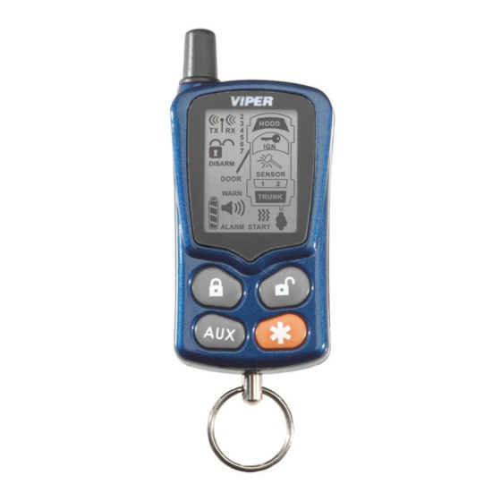
Page 39: Remote Control Diagram
remote control diagram © 2003 Directed Electronics, Inc. Vista, CA... -
Page 40: Standard Mode Configuration
standard mode configuration 1. Auxiliary Channel Out 2. Receive Indicator 3. Signal Indicator 4. Transmit Indicator 5. Lock Status Indicator 6. Unlock Status Indicator 7. Arming Status Indicator 8. Disarming Status Indicator 9. Door Switch Input Indicator 10. Warn Away® Response Indicator 11. -
Page 41: Multi-Level Security Arming
multi-level security arming Multi-Level Security Arming is a feature that allows the user to select which of the system's inputs or sensors will be active and which will be bypassed when the system is armed. (See Table of Zones section of this guide.) Multi-Level Security Arming can only be accessed from a standard configuration transmitter. -
Page 42: System Features Learn Routine
system features learn routine The System Features Learn Routine dictates how the unit operates. It is possible to access and change any of the feature settings using the Valet/program switch. However, this process can be greatly simplified by using the optional Personal Computer Interface or Bitwriter (p/n 998T). - Page 43 Program the Feature. While holding the Valet®/Program switch, you can toggle the feature on and off using the remote transmitter. Pressing the button that arms the system will select the one chirp or default setting. Pressing the button that disarms the system (or the Channel Two button when in the single button arm/disarm configuration) will select the two chirp setting.
-
Page 44: Feature Menus
To exit the learn routine: The learn routine will be exited if any of the following occurs: 1. Close the open door. 2. Turn the ignition on. 3. There is no activity for longer than 15 seconds. 4. The Valet®/Program switch is pressed too many times. feature menus The default settings are indicated in bold type. -
Page 45: Menu #3 - Remote Start Options
menu #2 - advanced features FEATURE NUMBER ONE-CHIRP SETTING (DEFAULT) TWO-CHIRP SETTING Siren output constant Siren output pulsed 30 second siren duration* 60 second siren duration* Nuisance Prevention Circuitry on Nuisance Prevention Circuitry OFF Progressive door trigger Instant door trigger Disarm from Valet, 1 pulse Disarm from Valet, 2-5 pulses Door sensor bypass chirp on... -
Page 46: Feature Descriptions
feature descriptions The features of the system are described below. Features that have additional settings that can be selected only when programming with the PC interface or Bitwriter are indicated by the following icon: menu #1 - basic features 1-1 ACTIVE/PASSIVE ARMING: When active arming is selected, the system will only arm when the transmitter is used. -
Page 47: Menu #2 - Advanced Features
"Type E - Mercedes-Benz and Audi -1985 and Newer" diagram.) 1-8 FORCED PASSIVE ARMING ON/OFF: To use this feature, passive arming must be selected in Feature 1-1. When turned on, forced passive arming will ensure that the system will passively arm, even if a zone is left open or invalid. - Page 48 system again. NPC™ only monitors sensor inputs, and does not bypass the door trigger or the ignition trigger at any time. If NPC™ is turned off, the system will respond to repeated triggers on the sensor inputs and will do so indefinitely.
-
Page 49: Menu #3 - Remote Start Options
2-11 CHANNEL 5 VALIDITY/LATCHED/LATCHED RESET WITH IGNITION/30 SECOND TIMED/SECOND UNLOCK OUTPUT: Channel Four can be programmed for these output configurations. The unit is set to the default valid- ity output. To change the configuration, use the two-chirp setting to toggle through the different configurations. menu #3 - remote start options 3-1 ENGINE CHECKING ON/OFF: In the default setting the remote start will monitor either the vehicle's tach wire or voltage depending on the programming of feature 3-2. -
Page 50: Nuisance Prevention Circuitry
3-8 ACTIVATION PULSE COUNT: This allows the system to use 1 or 2 pulses to activate the remote start sequence. Note! 1 or 2 pulses on the WHITE/BLUE remote start activation input wire as well as the button of the remote control. 3-9 2 nd IGNITION/2 nd ACCESSORY OUTPUT: This will allow the PINK/WHITE to be used as a 2 nd ignition or an accessory. -
Page 51: Valet Mode
valet mode To enter or exit valet mode with the valet/program switch: Turn the ignition key on and then off. At anytime during the next 10 seconds, press and release the Valet® switch. Now the Status LED will light constantly if you have entered Valet® Mode, and go out if you have exited Valet®... -
Page 52: Table Of Zones
To enter or exit timer mode manually: 1. Make sure the remote start system is not operating the engine. 2. Turn the ignition on. Timer Mode will be exited and the parking lights will flash four times. table of zones When using the Diagnostic functions, use the Table of Zones to see which input has triggered the system. -
Page 53: Long Term Event History
LED FLASHES SHUTDOWN MODE Timed out Over-rev shutdown Three Low or no RPM Four Transmitter shutdown (or optional push-button) (-) Shutdown (H3/3 GRAY) or (+) Shutdown (H3/4 BROWN) Seven (-) Neutral safety shutdown (H3/6 BLACK/WHITE) Eight Wait-to-start timed out long term event history The system stores the last two full triggers in memory. -
Page 54: Safety Check
safety check Before vehicle reassembly, the remote system must be checked to ensure safe and trouble-free operation. The fol- lowing test procedure must be used to verify proper installation and operation of the system. The installation must be completed before testing, including connection to the brake switch and hood switch. 1. -
Page 55: Troubleshooting
troubleshooting alarm troubleshooting Shock sensor doesn't trigger the alarm: Has the NPC™ system been triggered? If so, you will hear 5 chirps when disarming. To check this, turn the igni- tion key on and off to clear the NPC™'s memory, and then retest the shock sensor. For a detailed description of NPC™, see Nuisance Prevention Circuitry section of this guide. - Page 56 2. Check voltage and fuses. Use a meter to check for voltage between the red wire in the 5-pin ribbon harness and the black ground wire. If you have less than battery voltage, check the 3A and both 30A fuses on the relay satellite.
-
Page 57: Wiring Quick Reference Guide
wiring quick reference guide © 2003 Directed Electronics, Inc. Vista, CA... -
Page 58: Relay Satellite Wiring Quick Reference Guide
relay satellite wiring quick reference guide © 2003 Directed Electronics, Inc. Vista, CA...