Table of Contents
Advertisement
Advertisement
Table of Contents

Related Manuals for Viper 5500


Summary of Contents for Viper 5500
- Page 1 Model 5500 Owner's Guide...
-
Page 2: Limited Lifetime Consumer Warranty
Limited Lifetime Consumer Warranty Directed Electronics promises to the original purchaser to repair or replace with a comparable reconditioned model any Directed Electronics unit (hereafter the "unit"), excluding without limitation the siren, the remote transmitters, the associated sensors and accessories, which proves to be defective in workmanship or material under reasonable use during the lifetime of the vehicle provided the following con- ditions are met: the unit was professionally installed and serviced by an authorized Directed Electronics dealer;... - Page 3 HEREBY EXPRESSLY DISCLAIMS ANY LIABILITY WHATSOEVER, INCLUDING WITHOUT LIMITATION, LIABILITY FOR THEFT, DAMAGE AND/OR VANDALISM. THIS WARRANTY DOES NOT COVER LABOR COSTS FOR MAINTENANCE, REMOVAL OR REIN- STALLATION OF THE UNIT OR ANY CONSEQUENTIAL DAMAGES OF ANY KIND. IN THE EVENT OF A CLAIM OR A DISPUTE INVOLVING DIRECTED ELECTRONICS OR ITS SUB- SIDIARY, THE PROPER VENUE SHALL BE SAN DIEGO COUNTY IN THE STATE OF CALIFORNIA.
-
Page 4: Table Of Contents
Table of Contents Limited Lifetime Consumer Warranty ......i What is Included ........3 Important Information . - Page 5 Disabling the Remote Start System ....... . . 27 Programming Options .
-
Page 6: What Is Included
What is Included ■ The control module ■ SST 2 way receiver/antenna ■ One four-button LCD transmitter ■ A blue status LED indicator light ■ A push-button Valet switch ■ Your warranty registration ■ A shut-down toggle switch Important Information Congratulations on the purchase of your remote start keyless entry system. -
Page 7: Your Warranty
Your Warranty Your warranty registration must be completely filled out and returned within 10 days of purchase. Your product warranty will not be validated if your warranty registration is not returned. Make sure you receive the warranty registration from your dealer. It is also necessary to keep your proof of purchase, which reflects that the product was installed by an authorized dealer. -
Page 8: Caution
distance of 20 cm or more from the person’s body, except for the hand and wrists, to satisfy RF exposure compliance. This device is designed to be used in a person’s hands and its operating config- urations do not support normal transmissions while it is carried in pockets or holsters next to a persons’... -
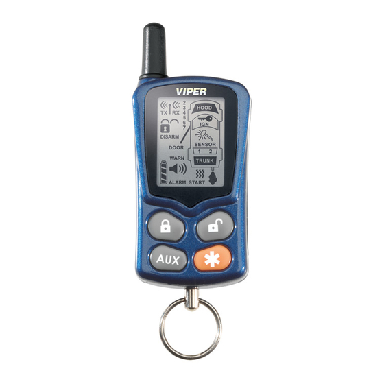
Page 9: Remote Control Diagram
Remote Control Diagram 2006 Directed Electronics—all rights reserved ©... -
Page 10: Standard Remote Configuration
Standard Remote Configuration 1. Auxiliary Channel Out 2. Receive Indicator 3. Signal Indicator 4. Transmit Indicator 5. Lock Status Indicator 6. Unlock Status Indicator 7. Not applicable 8. Not applicable 9. Not applicable 10. Not applicable 11. Siren Status Indicator 12. -
Page 11: System Maintenance
System Maintenance This system needs no specific maintenance beyond remote control battery replacement. The remote is powered by a 1.5V AAA battery. The Battery Level indicator has four level indicators that serve as a visual indication of battery charge. When the battery reaches a low charge level that requires replacement, the remote control will generate a single notification chirp, and the Battery Level indicator will flash continuously. -
Page 12: Standard Button Configurations
Standard Button Configurations Button Controls the system L L o o c c k k function by pressing this button for one second. Button Controls the system U U n n l l o o c c k k function by pressing this button for one second. -
Page 13: Standard Icon Configurations
Standard Icon Configurations Icon The transmit icon will be displayed while the remote control is transmitting a command to the vehicle. Icon The receive icon will be displayed while the remote control is receiving a page from the vehicle. Icon The signal icon will be displayed if a command is transmitted to the vehicle but a command page is not received. - Page 14 Icon Not applicable. Icon The siren icon will display when a security feature has been trig- gered. Icon The siren icon will display when a security feature has been trig- gered. This icon will remain displayed until the system’s page is cleared.
-
Page 15: Remote Operation And Programming
Icon Not applicable. Icon Not applicable. note: The icons which are ‘not applicable’ are only used when incorporated with a ESP2 Directed Security/Remote Start system. Icon The ignition icon will display if the ignition is turned on when the system (doors) are locked. Icon Not applicable. -
Page 16: System Signal Paging Features
System Signal Paging Features A page is the signal the 542 control module sends to the remote control as confirmation of receipt of a command. When the remote control receives a page it will generate a page notification to the user (notifications are audible beeps or remote vibration) and the LCD Icons will display the current system status. -
Page 17: Programmable Remote Control Features
Programmable Remote Control Features To enter programming mode Press and hold all four remote control buttons simultaneously until one long beep is heard. Programming Mode has now been entered. Page Notification The remote control can be programmed to notify the user of a page by audibly beeping or remote vibration. -
Page 18: Using Your System
Illumination On/Off Within five seconds of entering Programming Mode, press The remote will beep once for on, twice for off and the light will turn on/off with each press. Page Mode On/Off After entering Programming Mode, press seconds to toggle on and off. When the Page Mode is on, the remote control will wake up periodically to check for messages from the security module. - Page 19 ■ When properly installed, this system can start the vehicle via a command signal from the remote control transmitter. Therefore, never operate the system in an enclosed area or partially enclosed area without ventilation (such as a garage). When parking in an enclosed or partially enclosed area or when having the vehicle serviced, the remote start system must be disabled using the installed toggle switch.
- Page 20 ■ Use of this product in a manner contrary to its intended mode of operation may result in property damage, personal injury, or death. (1) Never remotely start the vehicle with the vehi- cle in gear, and (2) Never remotely start the vehicle with the keys in the ignition.
-
Page 21: Locking
INJURY. YOU MUST IMMEDIATELY CEASE THE USE OF THE UNIT AND SEEK THE ASSISTANCE OF AN AUTHORIZED DIRECTED ELECTRONICS DEALER TO REPAIR OR DISCONNECT THE INSTALLED REMOTE START MODULE. DIRECTED ELEC- TRONICS WILL NOT BE HELD RESPONSIBLE OR PAY FOR INSTALLATION OR REINSTALLATION COSTS. -
Page 22: Unlocking
If Passive Mode has been programmed on, then it is also possible to program the system for Passive Locking. With Passive Locking, the vehicle doors lock automatically at the same time that the Failsafe ® Starter Kill is activated. If Passive Locking is programmed on, care must be taken to prevent the keys from being locked in the vehicle. -
Page 23: Disabling The Starter Kill Without A Transmitter
Disabling the Starter Kill Without a Transmitter If your remote transmitter is lost or damaged, you can manually override the starter kill. To do this, you must have the vehicle's ignition key and know where the Valet switch is located. Be sure to check with the installer for the location of the Valet switch. -
Page 24: Panic Mode
To enter or exit Valet Mode: 1. Turn the ignition on. 2. Turn the ignition off. 3. Press and release the Valet switch within 10 seconds. The status LED will light steadily if you are entering Valet Mode and will turn off if you are exiting Valet Mode. Panic Mode If you are threatened in or near your vehicle, you can attract attention by triggering the system with your transmitter. -
Page 25: Remote Start
Remote Start This feature allows you to remotely start and run your vehicle for a programmable period of time. This makes it possible to warm up the engine, as well as adjust the interior temperature of the vehi- cle with the climate control system. If interior heating or cooling is desired, the climate controls must be preset, and the fan blower must be set to the desired level prior to remote starting the vehicle. -
Page 26: Rear Defogger
When you are ready to drive the vehicle: 1. Insert the ignition key and turn it to the ON (not the START) position. 2. Press the brake pedal. NOTE: If the brake pedal is pressed before the key is in the ON position, the engine will shut down. -
Page 27: Valet Take-Over
NOTE: If the remote start is on the parking lights will turn off then flash 2-times before returning to their normal output and the defogger out- put, if active, will cease. To turn the rear defogger output ON: 1. Simultaneously press & release the tons on the remote control. -
Page 28: Short-Run/Turbo
a shut-down input is received. (See the previous Remote Start section for a complete list of shut-down inputs.) NOTE: This feature will not work if the brake pedal is being pressed. Short-Run/Turbo Short run turbo mode keeps the engine running after arriving at you destination for a programmable period of 1, 3, 5 or 10 min- utes. -
Page 29: Starter Anti-Grind Circuitry
the timer mode will cancel. Press Timer mode buttons. The vehicle will confirm with 4 parking light flashes. A 1-second delay will start. The system will start the car and will run for the specified duration, unless shut down by the remote start button If shut down with the remote start button will remain in timer mode. -
Page 30: Rapid Resume Logic
Disabling the Remote Start System This feature allows your system's remote start unit to be tem- porarily disabled to prevent the vehicle from being remote started accidentally. This feature is useful if the vehicle is being serviced or stored in an enclosed area. To disable the remote start, move the shutdown toggle switch to the OFF position. -
Page 31: Programming Options
Programming Options Programming options control your system's normal, operational set-up. Most options do not require additional parts, but some may require additional installation labor. This system's programming options are listed below, with the factory default settings in bold: ■ 12, 24, or 60 minute run time. your system can be pro- grammed to allow the vehicle to run for 12, 24, or 60 min- utes when remote started. -
Page 32: Glossary Of Terms
■ Passive Locking or Active Locking (doors lock only with the transmitter). With Passive Locking, the vehicle doors lock automatically 30 seconds after the ignition has been turned off. Passive Locking can only be selected when the system has been programmed for Passive Mode. ■... -
Page 33: Convenience Expansions
Valet Switch: A small push button mounted at a discretionary location inside the vehicle. It is used to override the Failsafe ® Starter Kill when a transmitter is lost or damaged, or to enter or exit Valet Mode. Convenience Expansions Listed below are some of the many expansion options available for use with your system. - Page 34 grammed to operate a factory power release for the vehicle's trunk or hatch. If the factory release is not power-activated, Directed Electronics 522T trunk-release solenoid can often be added. Power Window Control: Power window control is provided with Directed Electronics 529T or 530T systems. The 529T system will roll up two windows automatically when the system is armed, or roll two windows down by using the transmitter.
-
Page 35: Notes
Notes 2006 Directed Electronics—all rights reserved ©... -
Page 36: Quick Reference Guide
QUICK REFERENCE GUIDE: To lock/arm using your remote ■ To arm the system press nected). The LED will begin to flash. The Failsafe vent the vehicle’s starter from cranking if it has been installed. The ve- hicle’s horn (if connected) will honk and the parking lights will flash once to confirm arming of the system. - Page 37 The company behind this system is Directed Electronics Since its inception, Directed Electronics has had one purpose, to provide consumers with the finest vehicle security and car stereo products and accessories available. The recipient of nearly 100 patents and Innovations Awards in the field of advanced electronic technology, Directed Electronics is ISO 9001 registered.