Table of Contents
Advertisement
Responder LE Model 5301
Remote Start Keyless Entry
Installation Guide
This product is intended for installation by a professional
installer only! Attempts to install this product by a person other than a
trained professional may result in severe damage to a vehicle's electrical
system and components.
© 2008 Directed Electronics, Vista, CA
N4202V 2008-06
Advertisement
Table of Contents

Related Manuals for Viper 5301


Summary of Contents for Viper 5301
- Page 1 Responder LE Model 5301 Remote Start Keyless Entry Installation Guide This product is intended for installation by a professional installer only! Attempts to install this product by a person other than a trained professional may result in severe damage to a vehicle’s electrical system and components.
- Page 2 Bitwriter®, Code Hopping™, Doubleguard®, ESP2™, Fail- Safe®, Ghost Switch™, Learn Routine™, Nite-Lite®, Nuisance Prevention® Circuitry, Revenger®, Silent Mode™, Soft Chirp®, Stinger®, Valet®, Vehicle Recovery System®, VRS®, and Warn Away® are all Trademarks or Registered Trademarks of Directed Electronics. The Bitwriter® (p/n 998U) requires chip version 2.5 or newer to program this unit.
-
Page 3: Table Of Contents
Contents Warning! Safety first ..................5 What is included ....................7 Installation points to remember ................7 Virtual tach ....................7 D2D ......................8 The control center ..................8 Valet® program switch ................9 Status LED ....................9 Before beginning the installation ...............10 After the installation ................10 Component locations and finding wires ............11 Making your wiring connections ...............11 Primary harness (H1), 12-pin connector .............12 Auxiliary harness (H2), 7-pin connector .............12... - Page 4 Feature menus ....................45 Menu 1 - Keyless entry ................45 Menu 2 - Convenience ................46 Menu 3 - Remote start ................47 Feature descriptions ..................48 Menu 1 - Keyless entry ................48 Menu 2 - Convenience ................50 Menu 3 - Remote start ................53 ®...
-
Page 5: Warning! Safety First
Warning! Safety first The following safety warnings must be observed at all times: • Due to the complexity of this system, installation of this product must only be performed by an authorized Directed Electronics dealer. • When properly installed, this system can start the vehicle via a command signal from the remote control. - Page 6 After the remote start module has been installed, test the remote start module in accordance with the Safety Check outlined in this installation guide. If the vehicle starts when performing the Neutral Safety Shutdown Circuit test, the remote start unit has not been properly installed. The remote start module must be removed or properly reinstalled so that the vehicle does not start in gear.
-
Page 7: What Is Included
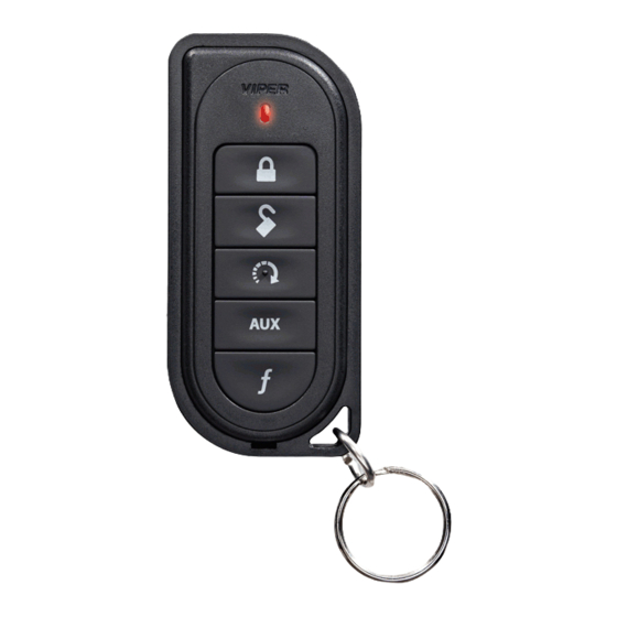
What is included • The control module • Control center with integrated status LED and Valet Override switch (p/n 6211T) • One five-button/2-way Supercode Responder LE Remote Control, (p/n 7251V) • One five-button /1-way Supercode Remote (p/n 7152V) • A shut-down toggle switch Installation points to remember This product is designed for fuel-injected, automatic transmission, or vehicles with manual transmissions. -
Page 8: D2D
➤ D2D The system has the ability to interface with an XK module through the D2D port. The advantage to using a D2D interface is that there is less wiring involved in the installation. Check the XK module installation guide to determine which wires are not needed, and which options are available. -
Page 9: Valet® Program Switch
➤ Valet® program switch The valet/program switch is built into the control center. Important: When the vehicle is delivered, please show the user where this switch is lo cat ed and how to disarm the sys- tem with it. Note: An optional valet switch (p/n #8631) is available if the onboard valet switch is not used for the install. -
Page 10: Before Beginning The Installation
➤ Before beginning the installation • Please read this entire installation guide before beginning the installation. The installation of this remote start system requires interfacing with many of the vehicle’s systems. Many new vehicles use low-voltage or multiplexed systems that can be damaged by low resistance testing devices, such as test lights and logic probes (computer safe test lights). -
Page 11: Component Locations And Finding Wires
Component locations and finding wires For detailed information on where to locate components, and how to find the wires you need, please refer to the Direct Tech web site at www.directechs. com. Making your wiring connections Before making your connections, plan how your wires will be routed through the vehicle. -
Page 12: Primary Harness (H1), 12-Pin Connector
➤ Primary harness (H1), 12-pin connector H1/1 RED/WHITE (-) 200mA TRUNK RELEASE OUTPUT H1/2 (+)12v CONSTANT INPUT H1/3 BROWN (-) HORN OUTPUT H1/4 WHITE/BROWN LIGHT FLASH ISOLATION WIRE - PIN 87a of onboard relay H1/5 BLACK (-) CHASSIS GROUND H1/6 VIOLET (+) DOOR TRIGGER INPUT* H1/7... -
Page 13: Heavy Gauge Remote Start, (H3) 8-Pin Connector
There are three harness connections relative to remote start function, including the heavy gauge and input and output harnesses. ➤ Heavy gauge remote start, (H3) 8-pin connector H3/1 PINK IGNITION 1 INPUT/OUTPUT H3/2 RED/WHITE (+) FUSED (30A) IGNITION 2 / FLEX RELAY INPUT 87 H3/3 ORANGE ACCESSORY OUTPUT... -
Page 14: Remote Start Auxiliary Output, 5-Pin
➤ Remote start auxiliary output, 5-pin PINK/WHITE (-) 200mA FLEX RELAY CONTROL OUTPUT ORANGE (-) 200mA ACCESSORY OUTPUT VIOLET (-) 200mA STARTER OUTPUT PINK (-) 200mA IGNITION 1 OUTPUT BLUE (-) 200mA STATUS OUTPUT Note: Wires 1 - 4 on the remote auxiliary outputs are wired to the (-) triggers for the onboard remote start relays and are not diode isolated. -
Page 15: Wire Connection Guides
Wire connection guides ➤ Primary harness (H1) H1/1 RED/WHITE (-) 200mA TRUNK RELEASE OUTPUT When the system receives the code controlling trunk release output for longer than 1.5 seconds, the red/white wire will supply an output as long as the transmission continues. - Page 16 H1/3 BROWN (-) HORN OUTPUT This wire supplies a (-) 200 mA output that can be used to honk the vehicle horn. It outputs a single pulse when locking the doors with the remote, and two pulses when unlocking with the remote. This wire also outputs pulses for 30 seconds when Panic Mode is activated.
- Page 17 H1/5 BLACK (-) CHASSIS GROUND We recommend that you do not use a factory ground. Ground all your compo- nents to the same point in the vehicle, (preferably the kick panel). Scrape away any paint and use a factory bolt or make your own ground with a self-tapping screw and a star washer.
- Page 18 H1/7 BLUE (-) FACTORY HORN INPUT This optional input can be wired to the factory horn honk output of the vehicle. When this wire receives an input for a minimum of .5 seconds, the system reports a trigger on the remote. This is useful on vehicles that have a factory security system, it notifies the owner that the system was triggered.
- Page 19 H1/9 BLACK/WHITE (-) 200mA DOME LIGHT OUTPUT Connect this wire to the optional dome light supervision relay as shown below: Important! This output is only intended to drive a relay. It cannot be connected directly to the dome light circuit, as the output cannot support the current draw of one or more light bulbs.
- Page 20 H1/11 WHITE PARKING LIGHT OUTPUT This wire should be connected to the parking light wire in the vehicle. See Set- ting the light flash polarity section of this guide for polarity settings. (+) Positive Light Flash Output WHITE H1/11 (+) LIGHT FLASH OUTPUT (-) Negative Light Flash Output WHITE H1/11 (-) LIGHT FLASH OUTPUT...
-
Page 21: Auxiliary Harness (H2)
➤ Auxiliary harness (H2) H2/1 LIGHT GREEN/BLACK (-) 200mA FACTORY ALARM DISARM OUTPUT This wire sends a negative pulse every time the remote start is activated , chan- nel 2 is activated (programmable on/off) or when the doors are unlocked with the remote. - Page 22 H2/3 WHITE/VIOLET (-) 200mA AUX 1 OUTPUT This wire provides 200 mA programmable output whenever the transmitter but- tons controlling Aux 1 channel is pressed. (See descriptions for Aux 3) Warning! Never use this wire to drive anything but a relay or a low-current input, supplied output is only 200mA.
- Page 23 • Latched, reset with ignition: Similar to the latched output, this type of output turns On the first time the Aux channel button is pressed, and turns Off the next time the same button is pressed. This type of output additionally stops and resets whenever the ignition is turned On and then Off.
- Page 24 Note: A 1-amp diode must be installed in line on the factory wire between the wait-to-start indicator and the ECM. (See the following diagram for details). (+)WAIT-TO-START WIRE © 2008 Directed Electronics. All rights reserved.
-
Page 25: Heavy Gauge, 8-Pin Connector
➤ Heavy Gauge, 8-pin connector There are 8 heavy gauge wires coming from the large 8-pin connector. They are used to energize the ignition circuits in the vehicle. It is crucial to ensure that these connections are capable of handling the current demands. For this reason, Scotch-Locks, T-taps and other such connectors are strongly discouraged. - Page 26 H3/7 PINK/BLACK FLEX RELAY INPUT 87A key side (if required) of FLEX RELAY This wire is used when an ignition switch isolation on the vehicle is necessary. This is common on Toyota and Nissans which required the use of Tech Tip document #1077.
-
Page 27: Remote Start Input - 5-Pin Connector
➤ Remote start input - 5-pin connector BLACK/WHITE (-) NEUTRAL SAFETY SWITCH INPUT Connect this wire to a ground source if installing this unit in an automatic trans- mission vehicle. If this unit is being installed in a manual transmission vehicle then connect it to the emergency brake wire. - Page 28 GRAY N/O or N/C (-) HOOD PIN SWITCH INPUT This wire MUST be connected to a hoodpin switch. This input will disable or shut down the remote start when the hood is opened. (See Feature Descriptions, Menu #1 feature 11 for details about programming.) BLUE/WHITE (-) 200 mA 2ND STATUS/REAR DEFOGGER OUTPUT...
-
Page 29: Remote Start Auxiliary Output, 5-Pin
➤ Remote start auxiliary output, 5-pin These signals are provided to drive additional optional relays. PINK/WHITE (-) 200mA FLEX RELAY CONTROL OUTPUT This wire is programmed as (-) 2nd ignition output from factory and can be programmed (to drive a relay) as a (-) starter or an accessory output. (See Feature programming Menu 3, feature 8.) ORANGE (-) 200mA ACCESSORY OUTPUT... -
Page 30: Door Lock Wire Diagrams
➤ Door lock wire diagrams Important: Depending on the vehicle, the door locks may be con- trolled by an optional data bus expansion module. If so, no door lock interface wiring is required. There are eight different types of door lock systems (Type A - H). Type A: Three-wire (+) pulse controlling factory lock relays. -
Page 31: Neutral Safety Switch Interface
Neutral safety switch interface Some vehicles do not have an electrical neutral safety switch. Instead, the ve- hicle has a mechanical neutral safety switch that physically interrupts the starter wire and is used when the vehicle is in any drive gear. If the remote start is interfaced before this switch, it will provide protection from starting in gear. -
Page 32: Plug-In Led And Valet/Program Switch
Plug-in LED and valet/program switch The LED and valet switch are incorporated into the control center the LED line will plug into the white 2-pin port and the Valet switch line will plug into the blue 2-pin port. Note Onboard LED and valet switch can be substituted with an optional out- board LED (P/N 8634 for Blue LED and 8633 for red LED) and an outboard valet switch (P/N 8631). -
Page 33: Tachometer Settings
Tachometer settings ➤ Virtual tach To program Virtual Tach: After the install is complete, remote start the car. If the car does not start on the first attempt, let the remote start attempt again. Once the car starts, let it run until the parking lights come on. When the parking lights come on, shut off the remote start with the remote - that's it! Virtual Tach is programmed. -
Page 34: Tach Learning
➤ Tach learning To learn the tach signal: 1. Start the vehicle with the key. 2. Within 5 seconds, press and hold the Valet/Program switch. 3. After 3 seconds the LED will light constant when the tach signal is learned. 4. -
Page 35: Tach Threshold On/Off
➤ Tach threshold On/Off In most cases, this jumper can be left in the Off position. Some new vehicles use less than 12 volts in their ignition systems. The unit may have trouble learning the tach signal in these vehicles. Changing the jumper to the On setting changes the trigger threshold of the digital tach circuit so that it will work with these type vehicles. -
Page 36: Setting The Light Flash Polarity
Setting the light flash polarity Light flash (+) / (-) polarity The internal fuse is used to determine the light flash output. In the (+) position, the onboard relay will output (+)12V on the WHITE wire, H1/11. In the (-) position, the on-board relay will supply a (-) output When wiring into a multiplex circuit, you can replace the fuse with a resistor (paying attention to the polarity setting). -
Page 37: Remote Control Learn Routine
Remote control learn routine The system comes with a 1-way and a 2-way remote control that are already programmed to the system. The system can store up to 4 different remote control codes in memory. The remote uses a Supercode Protocol and requires setup before programming the system. - Page 38 The Valet/Program switch, plugged into the blue port, is used for programming. There is a basic sequence to remember whenever programming this unit: Door, Key, Choose, Transmit and Release. Insert the key. Turn the ignition to the ON position. The heavy gauge pink wire must be con- nected.
- Page 39 Step Function Auto Learn Standard Configuration (default) The auto learn configuration will automatically setup the remote button configuration. Note: Due to the Supercode protocol, you cannot change the configuration. Delete remotes: This feature will erase all remotes from the memory of the system.
-
Page 40: Remote Control Configuration
Remote control configuration ➤ Responder LE 2-way A U X Note: The one-way remote only has the transmit LED and will not give any confirmation tones. Note: If Keypad Lock is On, press and then press to exit. The remote control buttons that operate the features of the remote start system are described below. - Page 41 For more information about the remote control functions, see the Owners Guide. Direct Access Level Button Lock Silent Lock Unlock Silent Unlock Valet Mode Car Finder Remote Start Reset Timer Mode Smart Start Rear A U X Runtime Defogger A U X Trunk Release AUX 1 AUX 2...
-
Page 42: System Features Learn Routine
System features learn routine The System Features Learn Routine dictates how the unit operates. It is possible to access and change any of the feature settings using the Valet/program switch. However, this process can be simplified by using the Bitwriter®. Any of the settings can be changed and then assigned to one of four remote controls. - Page 43 Select a Feature. Press and release the Valet/Pro- gram switch the number of times corresponding to the feature you wish to change. For example, to access the third feature, press and release 3 times. Then press the button once more and HOLD it.
- Page 44 To access another feature in the same menu: Press and release the Valet/Program switch the number of times necessary to advance from the feature you just programmed to the next one you want to program. Then press the Valet/Program switch once more and hold it. For example, if you just programmed the third feature in the menu and you want to program the seventh feature in the menu, press and release the Valet/Program switch four times and then press it once more and hold it.
-
Page 45: Feature Menus
Feature menus ➤ Menu 1 - Keyless entry Default settings are indicated in bold type. Menu Feature Opt. 1 Opt. 2 Opt. 3 Opt.4 Opt. 5+ Item System Active Passive Auto relock- locking Locking locking Panic Mode Ign Off only Horn function Confirma- Confirma-... -
Page 46: Menu 2 - Convenience
➤ Menu 2 - Convenience Menu Feature Opt. 1 Opt. 2 Opt. 3 Opt.4 Opt. 5+ Item One-time Bypass Valet Switch Pulse Count Door ajar Error honk Ign-controlled Dome light OEM Alarm Disarm w/ OEM Alarm With Before Unlock Remote Start Disarm Output Unlock Only... -
Page 47: Menu 3 - Remote Start
➤ Menu 3 - Remote start Menu Feature Opt. 1 Opt. 2 Opt. 3 Opt.4 Opt. 5 Item Transmission Manual Automatic Mode Engine Virtual Tach Voltage Tachometer Checking Mode Cranking 0.6 sec 0.8 sec 1.0 sec 1.2 sec Time (5)/1.6(6)/ 1.8 (7) 2.0(8)4.0(9) Remote Start... -
Page 48: Feature Descriptions
Feature descriptions The features of the system are described below. Features that have additional settings that can be selected only when programming with the Bitwriter® are indicated by the following icon: Default settings are in bold. The numbers in parentheses indicate the number of times the control center LED flashes. - Page 49 1-3, Horn Function: Turns On/Off the confirmation honks when locking/unlock- ing. Use it to change the output pulse duration for vehicles that require a longer pulse for the horn to honk. Confirmation honks ON (20mS) & panic, (1) Confirmation honk (30mS) & panic, (2) Confirmation honk (40mS) & panic (3) Confirmation honk (50mS) &...
-
Page 50: Menu 2 - Convenience
1-8 Comfort Closure Off(1): The system can be programmed to close the win- dows when the system is locked. If programmed ON, the lock output provides a 20 second pulse when the system is locked. The output will be cancelled if the unlock button is pressed. - Page 51 2-2 Valet switch pulse count, 1 pulse . Optional starter kill emergency override. From valet, 2 - 5 pulses. The system can be programmed to count the number of presses of the valet switch before disabling the optional starter kill. The factory default setting is one pulse.
- Page 52 2-8 Aux 1 Validity (1) Latched (2), Latch reset w/ignition (3), 30-sec. timed • Validity: Output that will send a signal as long as the transmission is re- ceived. • Latched: Output that will send a signal when the Aux 1 button is pressed and will continue until the same button) is pressed again.
-
Page 53: Menu 3 - Remote Start
2-13 Aux 3 Linking None (1) Lock (2) Unlock (3) Lock/Unlock (4) Smart key control (link to remote start Off. (5). When aux 3 is programmed to Smart Key control, this wire outputs a 800ms pulse when the Remote Start is shut Off. The system also monitors the door trigger input. - Page 54 3-3 Crank Time 0.6 0.8 (2) 1.0 (3) 1.2 (4) 1.4 (5) 1.6 (6) 1.8 (7) 2.0 (8) 4.0 (9) SECONDS: If the unit is programmed for no engine checking or voltage sense, the crank time must be set to the appropriate duration. The default setting is 0.6 second and the LED will flash once.
- Page 55 3-8 Flex Relay Function: Ignition 2 (1) In the factory setting, the flex relay will function the same as the pink ignition 1 wire, in accessory setting the flex relay will function the same as the Orange accessory 1 wire, in starter setting the flex relay will function the same as the purple starter 1 wire.
- Page 56 3-14 Tach Mode Starter Release: Normal: Use the two-honk setting to in- crease time by 15% of the original tach programmed time. The LED will flash twice (2). To decrease by 15% of the original programmed time, the LED will flash three (3) times.
-
Page 57: Bitwriter
➤ Bitwriter ® The Bitwriter® has the ability to fine tune certain features of the system. These features and the adjustments that may be programmed are described in the table that follows. Note: Feature programming for Responder LC remote controls with a display screen are available when using the Bitwriter, however these features do not apply to this LE system. -
Page 58: Valet Mode
Valet mode To enter or exit valet mode with the valet/program switch: Turn the ignition key on and then off. At anytime during the next 10 seconds, press and release the Valet switch. Now the Status LED will light constantly if you have entered Valet®... -
Page 59: Remote Starting The Vehicle
Remote starting the vehicle Before using the remote start be sure the vehicle is parked in a safe area with proper ventilation. To remote start the vehicle: • Press the button on the remote control. The vehicle parking A U X lights flash. -
Page 60: Manual Transmission Remote Start
Manual transmission remote start If the vehicle has a manual transmission the proper steps must be followed be- fore leaving the parked vehicle or the remote start feature is disabled. Make sure the engine is running and the doors on the vehicle are closed. Put the transmission in neutral. -
Page 61: Timer Mode
Timer mode This unit can be programmed to start and run the engine every three hours, for a maximum of six cycles. The engine will run for the programmed run time and then shut down. After three hours, the system will restart the engine. Important: Use Timer Mode in open areas only. - Page 62 To exit timer mode without the transmitter: Make sure the remote start system is not operating the engine. Turn the ignition on. Timer Mode is exited and the parking lights flash slowly four times. Note: The Bitwriter can change the amount of times the remote start activates and, it can change the intervals between activations in timer mode.
-
Page 63: Shutdown Diagnostics
Note: An optional push button can be hard wired to the (-) activation input of the system to activate turbo timer manually. When the vehicle is running follow the procedures listed above, but instead of pressing the remote, press the push button the appropriate number of times to activate the remote start (factory setting is for 1 pulse). -
Page 64: Remote Starting Diagnostics
Remote starting diagnostics When the remote start function is activated and the 2-way remote emits an er- ror tone, you can determine the cause of the no-start situation by counting the number of parking light flashes from the vehicle. Parking Light Flashes Brake wire is active Hoodpin wire is active... -
Page 65: Remote Start Safety Check
Remote start safety check Before vehicle reassembly, the remote start system must be checked to ensure safe and trouble-free operation. The following test procedure must be used to verify proper installation and operation of the system. The installation must be com- pleted before testing, including connection to the brake switch and hood switch. -
Page 66: Troubleshooting
Troubleshooting ➤ Keyless entry system • System will not passively lock until it is remotely locked and then un- locked: Are the door inputs connected? Is the H1/6 blue wire connected to the door trigger wire in the vehicle? Either the H1/5 green or the H1/7 violet should be used instead. - Page 67 • The remote start will activate, but the starter never engages. Check for voltage on the purple starter wire two seconds after the remote start becomes active. If there is voltage present, skip to Step 4. If there is not voltage present, advance to Step 2. Check the 30A fuses.
- Page 68 • The vehicle starts, but will only run for 10 seconds. Is the remote start programmed for voltage sense? If this does not work, a tach wire should be used. Check shutdown diagnostics. • The climate control system does not work while the unit is operating the vehicle.
- Page 72 N4202V 2008-06 Vista, CA 92081 www.directed.com © 2008 Directed Electronics—All rights reserved...