Table of Contents
Advertisement
Advertisement
Table of Contents

Related Manuals for Dynacord PM 502


Summary of Contents for Dynacord PM 502
- Page 1 PM 502 en | User manual...
-
Page 3: Table Of Contents
PM 502 Table of Contents | en Table of contents Safety Quick overview Shipping contents and warranty System overview Installation Connection Mains input Audio inputs 5.2.1 Mono inputs (MIC/LINE) 5.2.2 Stereo inputs Audio outputs 5.3.1 Speaker connection 5.3.2 Line level/USB 5.3.3... -
Page 4: Safety
| Safety PM 502 Safety Danger! The lightning symbol inside a triangle notifies the user of high-voltage, uninsulated lines and contacts inside the devices that could result in fatal electrocution if touched. Warning! An exclamation mark inside a triangle refers the user to important operating and service instructions in the documentation for the equipment. - Page 5 PM 502 Safety | en 15. To ensure the device is completely free of voltage, unplug the device from the power supply. 16. When installing the device, ensure that the plug is freely accessible. 17. Do not place any sources of open flame, such as lit candles, on top of the device.
- Page 6 | Safety PM 502 Old electrical and electronic appliances Electrical or electronic devices that are no longer serviceable must be collected separately and sent for environmentally compatible recycling (in accordance with the European Waste Electrical and Electronic Equipment Directive).
-
Page 7: Quick Overview
Quick overview | en Quick overview Your PM 502 is designed so that you can easily set it up and start using it right away. Follow the steps on the next few pages to set up your PM 502. Caution! Read all the instructions in this document and the safety notes starting on page 4 before you plug your PM 502 into a power outlet. -
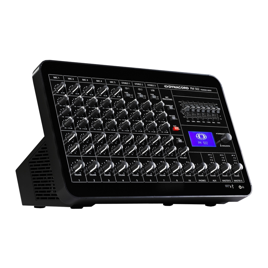
Page 8: System Overview
| System overview PM 502 System overview Front view Rear view 15-May-14 | 02 | F01U297804 User manual Bosch Sicherheitssysteme GmbH... -
Page 9: Installation
Using the RMK 502 Rack mount kit The RMK 502 Rack mount kit allows the PM 502 to be securely placed into a 19 inch rack, desk or table without covering the ventilation slots. When installing the PM 502 into a rack, please ensure sufficient ventilation. -
Page 10: Connection
Please, do not connect E-guitars or E-basses with passive, high impedance outputs directly to a MIC/LINE input. The MIC/LINE inputs of the PM 502, as with the line level inputs of mixers from other manufacturers, are designed for the connection of the relatively low source impedance of electronic instruments. -
Page 11: Stereo Inputs
STEREO 3 inputs at the same time. Notice! Always check the audio volume setting in your operating system after connecting the PM 502 to your PC. For the best signal-to-noise ratio the volume setting of your PC should be set to maximum level. -
Page 12: Audio Outputs
Euroblock connectors only, please refer to the following sections. speakON The PM 502 is equipped with professional speakON high-performance connectors, offering electrical and mechanically secure connection, which complies to all security regulations. It also allows the use of high quality speaker cables with diameters of 4 x 2.5 mm . - Page 13 PM 502 Connection | en Euroblock connector in low-Z mode When the Direct Drive mode is not activated, the Euroblock connector CH 1/2 +/- is in parallel to the speakON connectors CH 1/2 and can be used alternatively. Figure 5.1: Connection of low impedance speakers Euroblock connector in high-Z mode When the Direct Drive mode is activated, use pin + of CH 1 and pin –...
-
Page 14: Line Level/Usb
| Connection PM 502 5.3.2 Line level/USB Notice! All outputs are designed in Ground Sensing technology to prevent the induction of external noise, even with long cables. Use balanced cables for the connection of external components whenever it is possible. -
Page 15: Headphone
Notice! Powering external drives through USB The USB 2.0 port of the PM 502 provides up to 500 mA to USB peripherals. Peripherals exceeding this limit may not work properly, make sure to use an external power adaptor to supply such devices. -
Page 16: Configuration
5 MIC/LINE inputs together. 100 V Direct Drive The 100 V Direct Drive mode of the PM 502 allows connection of 100 V loudspeaker lines in high impedance mode (High-Z) without using output transformers. In this case the maximum number of loudspeakers connected to an output channel is only limited by the amplifier‘s... -
Page 17: Speaker Processing (Lpn)
Table 6.1: Amplifier routing Speaker processing (LPN) The power amplifier channels of the PM 502 incorporate Low-Pass-Notch filters (LPN) exclusively designed by DYNACORD. The LPN filter corrects the frequency and phase response of the connected loudspeakers. This effect can not be achieved using equalizers or „Bass- Boosters“, because the LPN filter mainly optimizes the transient response of the connected... -
Page 18: Locking
Table 6.3: AUX modes Locking The PM 502 allows locking certain features or parameter settings in the menu. A four digit PIN is used to lock or unlock the device. You can use one of three predefined locking levels or select manually which parts of the menu should be locked, please refer to the following table for details. -
Page 19: Microphone Processing (Talk Over)
Table 6.4: Locking levels (- = available, X = locked) Microphone processing (TALK OVER) The integrated ducker of the PM 502 reduces the level of the signals at the STEREO inputs whenever a signal is present at the MIC/LINE inputs (above the THRESHOLD level). If there is no MIC/LINE signal present the STEREO signal automatically returns to its preset level. -
Page 20: Operation
S/N-ratio and provides you with the full bandwidth of the PM 502’s outstanding sound capabilities. The following gain setting instruction is to be used as a guide to help achieve a good signal input level: Set the MASTER volume controls to their minimum values (counterclockwise). - Page 21 The peak indicator plays a key role when setting input levels. The PK (peak) LED on the PM 502 provides a visual indication of the risk of distortion before you hear it through the connected speaker systems. The peak indicator checks the signal level pre and post of the channel’s VOLUME control and indicates the maximum of both levels.
-
Page 22: Stereo Input
The peak indicator plays a key role when setting input levels. The PK (peak) LED on the PM 502 provides a visual indication of the risk of distortion before you hear it through the connected speaker systems. The peak indicator checks the signal level pre and post of the channel’s VOLUME control and indicates the maximum of both levels. - Page 23 +15 dB, we would like to advise you to exceed the “8” mark only in very few exceptional cases. If the PM 502’s summing bus gets “overloaded” with too many “high level” input channels, despite its special gain structure, the summing amplifier could be driven into clipping.
-
Page 24: Aux
OUTPUT SETTINGS menu, please refer to section Menu, page 26. Below the LIM indicator, the PM 502 offers a 3-segment LED chain for visual monitoring of the output level of the signal. The meter’s 0 dB mark is referenced to a 0 dBu output signal at the mixer output. -
Page 25: Equalizer
Engage the MUTE switch to mute all MIC/LINE input signals. Equalizer The PM 502 employs a 7-band stereo graphic equalizer (GEQ). Seven frequency bands offering 10 dB gain/reduction and a quality of Q = 1.5 allow the shaping of the overall sound to meet your personal preferences or to optimally match it to the acoustic conditions of different locations. -
Page 26: Display
The PM 502 includes a back-lit LC-display. Home screen The home screen appears after switching the PM 502 on. After a few seconds the currently selected effect (number and name) is displayed. If effect parameters have been edited, an “E”... - Page 27 PM 502 Operation | en Menu item Subitems/parameter range Description (default setting in bold) EDIT FX Depends on effect type. This dialog allows editing effect parameters of the effect unit. Select RESET to reset all parameters to their default values.
- Page 28 | Operation PM 502 Menu item Subitems/parameter range Description (default setting in bold) SPEAKER PROC • Low Pass Notch: Flat, This menu is used to edit the LPN Medium, High Speaker Processing filter setting of the integrated power amplifiers.
- Page 29 Pressing the MENU/ENTER rotary encoder opens a “Reset all settings?” safety dialog box. Select YES to reset the PM 502 to its factory settings. Select NO to return to the DEVICE SETUP menu. If the device is locked a factory reset is not possible.
-
Page 30: Indicators
| Operation PM 502 Indicators This section describes the indicators at the front panel of the PM 502. Indicator Description SPEAKER PROCESSING This indicator lights up blue when the internal speaker processing of the PM 502 is activated in the menu. Please refer to section Speaker processing (LPN), page 17 for more details about this mode. -
Page 31: Headphone Volume
PM 502 Operation | en 7.10 Headphone volume This control sets the volume of the connected headphones (see section Headphone, page 15). Caution! Make sure to set the PHONES VOLUME control to its minimum position before connecting headphones. Permanent hearing loss may occur if headphones are used at high volume. -
Page 32: Maintenance
| Maintenance PM 502 Maintenance The PM 502 does not require any maintenance. 15-May-14 | 02 | F01U297804 User manual Bosch Sicherheitssysteme GmbH... -
Page 33: Technical Data
PM 502 Technical data | en Technical data Channels (mono + stereo) 5 + 3 Microphone inputs 5 x XLR/Jack socket Auxiliaries (FX, AUX) 1 Post, 1 Pre Max. single channel output power, dynamic headroom, IHF-A • into 4 Ω... - Page 34 | Technical data PM 502 • Any input to Speaker output 20–22000 Hz Crosstalk, 1 kHz • Amplifier Ch1/Ch2 < -85 dB • Channel to channel < -78 dB Microphone mute switch attenuation > 100 dB Channel VOL and FX/AUX send attenuation >...
- Page 35 PM 502 Technical data | en Output stage topology, amplifier Class D Equalization • Low shelving filter ±15 dB / 60 Hz • Mid peak filter ±12 dB / 2.4 kHz • High shelving filter ±15 dB / 12 kHz Master EQ 7-band (63, 160, 400, 1k, 2.5k, 6k,...
- Page 36 | Technical data PM 502 • Switching mode power supply (μC Inrush current limiters, mains over/ controlled) undervoltage, mains over current, high temperature Cooling Continuous speed controlled fan Phantom power, switchable 48 V DC AC power input 100–240 V AC, 50–60 Hz...
-
Page 37: Dimensions
PM 502 Technical data | en Dimensions Bosch Sicherheitssysteme GmbH User manual 15-May-14 | 02 | F01U297804... -
Page 38: Circuit Diagram
| Technical data PM 502 Circuit diagram 15-May-14 | 02 | F01U297804 User manual Bosch Sicherheitssysteme GmbH... -
Page 39: Appendices
System examples Bistro or club In this application the integrated amplifier of the PM 502 drives three TS 100 speakers per output channel (low-Z mode). Powered speakers and subwoofers are connected to MASTER B or AUX OUT. Signal sources are connected via mic/line level inputs and USB. Additionally an USB stick is connected for using the internal audio player. - Page 40 PM 502 Live music In this application the integrated amplifier of the PM 502 drives one C 15.2 speakers per output channel (low-Z mode). Powered speakers (e.g. D 8A) as side room PA are connected to MASTER B. Powered monitor speakers (e.g. AXM 12A) are connected to AUX OUT. Signal sources are connected via mic/line level inputs.
- Page 41 Appendices | en Church or mosque In this application the integrated amplifier of the PM 502 drives a 100 V speaker line with ceiling speakers (Direct Drive, high-Z mode). A SL power amplifier driving four TS 100 speakers is connected to MASTER A output (set to Mono). A PCL power amplifier driving four DL 800 horns is connected to MASTER B (set to Mono).
- Page 42 PM 502 Mall or large shop In this application the integrated amplifier of the PM 502 drives a 100 V speaker line (zone 1) with ceiling speakers (Direct Drive , high-Z mode). A PowerSub 312 driving six TS 100 speakers is connected to MASTER A output. A PCL power amplifier driving another 100 V speaker line (zone 2) with ceiling speakers is connected to MASTER B (set to Mono).
-
Page 43: Pin Assignments
PM 502 Appendices | en 10.2 Pin assignments UNBALANCED SHIELD Figure 10.1: Unbalanced assignment of mono jack BALANCED SHIELD COLD Figure 10.2: Balanced assignment of stereo jack Figure 10.3: Pin assignment of XLR microphone input with phantom power Figure 10.4: Pin assignment of speaker output CH 1/2 (low-Z, speakON) - Page 48 Bosch Sicherheitssysteme GmbH Robert-Bosch-Ring 5 85630 Grasbrunn Germany www.dynacord.com © Bosch Sicherheitssysteme GmbH, 2014...