Dynacord POWERMATE 1000 Owner's Manual
Power mixer
Hide thumbs
Also See for POWERMATE 1000:
- Owner's manual (33 pages) ,
- Bedienungsanleitung (32 pages) ,
- Brochure & specs (8 pages)
Table of Contents
Advertisement
Available languages
Available languages
Advertisement
Chapters
Table of Contents

Related Manuals for Dynacord POWERMATE 1000


Summary of Contents for Dynacord POWERMATE 1000
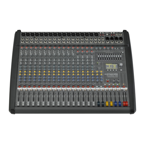
- Page 1 BEDIENUNGSANLEITUNG OWNER‘S MANUAL MODE D‘EMPLOI PowerMate 1000/1600 Power Mixer...
-
Page 2: Table Of Contents
EU-Staaten bitten wir Sie, sich an Ihren örtlichen Händler zu wenden. Wir haben ein eigenes System zur Verarbeitung elektronischer Abfälle und gewährleisten die kostenfreie Entgegennahme aller Produkte der EVI Audio GmbH: Telex, Dynacord, Electro-Voice, Midas Consoles, KlarkTeknik und RTS. Wir haben mit dem Händler, bei dem Sie Ihr Produkt gekauft haben, eine Vereinbarung getroffen, dass alle nicht mehr verwendbaren Geräte zur umweltgerechten Entsorgung kostenfrei an das Werk in... -
Page 3: Wichtige Sicherheitshinweise
WICHTIGE SICHERHEITSHINWEISE Das Blitzsymbol innerhalb eines gleichseitigen Drei- ecks soll den Anwender auf nicht isolierte Leitungen und Kontakte im Geräteinneren hinweisen, an denen hohe Spannungen anliegen, die im Fall einer Berührung zu lebensgefährlichen Stromschlägen führen können. Das Ausrufezeichen innerhalb eines gleichseitigen Dreiecks soll den Anwender auf wichtige Bedienungs- sowie Servicehinweise in der zum Gerät gehör- enden Literatur aufmerksam machen. -
Page 4: Beschreibung
BESCHREIBUNG Wir möchten Ihnen zu allererst danken und Sie beglückwünschen, dass Sie sich für einen Power Mixer von DYNACORD entschieden haben. Die PowerMate Kompaktanlagen basieren auf mehreren Jahrzehnten Erfahrung, Forschung und Kundennähe im professionellen Audiobereich. Mit dem PowerMate haben Sie einen leistungsfähigen Power Mixer erworben, der Ihnen eine große Anzahl von Funktionen in einer sehr kompakten Form, und dennoch kompromisslosen... -
Page 5: Input Mono
INPUT MONO 1. MIC Elektronisch symmetrische XLR-Eingänge zum Anschluß niederohmiger Mikrofone, wie sie auch in großen Studio- oder Livekonsolen verwendet werden. Diese Art der Eingangsstufe ist extrem rausch- und brummarm, darüberhinaus weist sie einen äußerst niedrigen Klirrfaktor (typ.<0.002%), auch bei hohen Frequenzen auf. Sie können hier im Prinzip jedes Mikrofon anstecken, sofern Sie dabei auf die Pin-Belegung entsprechend der untenstehender Abbildung achten. - Page 6 INPUT MONO Achten Sie bitte darauf, daß vor dem Anschluß von Signalquellen die jeweiligen Kanal- regler, mindestens jedoch die beiden Masterregler, geschlossen sind, oder der STANDBY- Schalter gedrückt ist. Sie ersparen sich selbst, Ihrem Publikum und Ihrem Equipment unnötige Beanspruchungen durch Knackgeräusche. 3.
- Page 7 INPUT MONO 5. LO CUT 80 Hz Mit dem LO CUT Schalter können Baßfrequenzen unterhalb 80 Hz mit einer Flankensteilheit von 18 dB pro Oktave unterdrückt werden. Sinnvoll ist die Benutzung des LO CUT-Filters vorallem bei allen Mikrofonanwendungen, wobei hier die Abnahme von Bassdrum oder Bass gesondert zu betrachten ist.
- Page 8 INPUT MONO MID EQ LOW-HI EQ Im Mittenbereich können Sie am effektivsten Einfl uß auf das Klangbild nehmen, wobei sich aber das Auffi nden der optimalen Arbeitsfrequenz mit dem Frequenzsteller nicht immer ganz einfach gestalltet. Darum hier eine Möglichkeit ( unter vielen ) wie Sie schnell eine für Ihre An- wendung passende Einstellung des parametrischen EQs fi...
- Page 9 INPUT MONO sinnvoller sein. Indem Sie alle AUX3 oder AUX4 Regler in Mittelstellung bringen, wird praktisch die Hauptabmischung auf den Monitormix übernommen und die Lautstärkeverhältnisse der einzelnen Kanäle zueinander können bequem auch von der Bühne aus kontrolliert werden. Die Monitorlautstärke wird über den AUX3/AUX4 Fader im Master eingestellt. Beachten Sie aber, dass ein Aufziehen eines Kanalfaders sich auf den Monitormix auswirkt und bei unbedachter Bedienung eine erhebliche Rückkopplungsgefahr besteht.
-
Page 10: Input Stereo
INPUT STEREO Wir wollen Sie hier bei der Beschreibung des STEREO-INPUTS nicht langweilen, viele Funk- tionsgruppen wie AUX-Regler, Eingänge, Kanalfader im STEREO INPUT sind identisch zum MONO INPUT aufgebaut und wurden dort bereits ausführlich erklärt. Wir wollen hier nur die wesentlichen Unterschiede herausarbeiten. - Page 11 INPUT STEREO 18. LINE TRIM Mit diesem Regler wird das Signal an den Line-Eingängen im Stereokanal an den internen Arbeitspegel des Mischpultes angepaßt. Der Regelbereich liegt bei 30 dB. Die Unity Gain Posi- tion, also 0 dB Durchgangsverstärkung, ist hier bei der Markierung 0 dB. Sie können mit diesem Regler das Signal um10 dB abschwächen bzw.
- Page 12 INPUT STEREO 20. AUX / FX Mit diesen Reglern wird das aus L und R summierte Signal POST-FADE auf die AUX/FX- Summenschienen ausgespielt. Die Funktionsweise wurde bereits im INPUT/MONO erläutert. 21. AUX3/4 Legt das aus L und R summierte Signal auf die AUX3- bzw. AUX4 Summenschiene. Dies kann entweder POST-FADER oder PRE-FADER geschehen und wird wie im Monokanal über den AUX PRE/ POST Schalter im Masterbereich ausgewählt.
-
Page 13: Effekt 1/2
Frontblende. Beachten Sie bitte auch die FOOTSWITCH-Buchsen. Hier können Sie Fußschalter zur Fernsteuerung der EFFEKT ON/OFF Funktion anschließen. Verfügt Ihr Fußschalter über eine LED z.B. FS11 aus dem DYNACORD Zubehörprogramm, dann wird diese bei EFFEKT ON leuchten. Umstellung der Effekt-Startprogramme Die Effektsektion startet werkseitig mit den Programmen 5/55. - Page 14 EFFEKT 1/2 29. DISPLAY Das Display zeigt immer die aktuell eingestellte Programmnummer des jeweiligen Effekt- teils an. Zum Schutz vor Verkratzen ist das Displayglas bei Auslieferung mit einer Folie abgedeckt. Ziehen Sie diese bitte ab. 30. UP/DOWN Mit den UP/DOWN-Tasten werden die Effektprogramme angewählt. Wenn Sie länger auf eine dieser Tasten drücken, können Sie dadurch einen schnellen Vor- bzw.
-
Page 15: Aux3/4
AUX3/4 Der AUX3/4-Kanalzug wird im wesentlichen zum Monitoring verwendet. Über die AUX3/4 POST Taste, ist es aber auch möglich hier einen zusätzliches externes Effektgerät zu betreiben. 37. AUX3/4 SEND Hier schließen Sie entweder ein Effektgerät oder im Monitorbetrieb eine Monitorendstufe bzw. einen Aktivmonitor an. -
Page 16: Master
MASTER 42. AUX3/4 VOLUME Dieser Schieberegler regelt das AUX3/4-Summensignal auf den AUX3/ 4 SEND-Ausgang und ist somit beim Monitoring der Lautstärkeregler für die Monitoranlage. 43. 7-BAND EQUALIZER Im linken sowie rechten Masterkanal kann je ein 7-band Equalizer über die EQ ON Taste eingeschaltet werden. Der EQ liegt dann schaltungstechnisch nach den Master-Schiebereglern und vor der Leistungsendstufe. - Page 17 MASTER PROTECT leuchtet dann auf, wenn eine der umfangreichen Schutz- schaltung wie Übertemperatur-, Hochfrequenz-,Gleichspannungs-, oder SOAR-Schutzschaltung im Leistungsverstärker aktiv ist. Um die Leis- tungsverstärker vor Zerstörung zu schützen werden im Protect Mode die Lautsprecher abgeschalten und der Eingang der Endstufe deakti- viert.
- Page 18 MASTER 49. MONO OUTPUT Der Mono-Ausgang führt das summierte Master L/R Signal, und kann für Monito- ring, Sidefi ll, Nebenraumbeschallung, Mono-PA und zum Anschluß einer Delay- Line oder Subwoofer verwendet werden. 50. MONO OUT Für viele Anwendungen wie Subwooferbetrieb, Nebenraumbeschallung, Monitoring oder Delay Line ist es vorteilhaft einen pre/post schaltbaren Mono- Ausgang zur Verfügung zu haben.
- Page 19 MASTER 55. 2TRACK to MASTER Mit diesem Regler wird das 2TRACK Signal dem MASTER-Kanal POST-FADER zuge- mischt. Achtung: Gehen Sie beim Einpegeln des am 2TRACK RETURN angeschlos- senen externen Gerätes wie z.B. CD-Player oder Tape-Deck immer vom Regler im Linksanschlag aus, da z.B. je nach Qualität der Aufnahme relativ schnell eine sehr hohe Endstufenausgangsleistung erzeugt werden kann.
- Page 20 Klinkenbuchsen zum Anschluß eines Fußschalters FS11 (110 693) aus dem DYNACORD Zubehörprogramm. Die eingebauten Effektteile können damit ein- und ausgeschaltet werden. Zur Fernsteuerung mittels Fußschalter müssen die Effektge- räte über die FX1 bzw. FX2 ON Schalter im Effektkanal aktiviert sein.
-
Page 21: Rückseite
Verbindung wird allen Sicherheitsanforderungen gerecht und erlaubt die Verwendung von Hochleistungslaut- sprecherkabeln von bis zu 4 x 2,5mm Querschnitt. Im DYNACORD-Zubehörprogramm fi nden Sie Einzelstecker und Kupplungen sowie Hochleistungslautsprecherkabel. Warnung: Das Symbol “ ”, das die Lautsprecheranschlüsse markiert, zeigt an, daß hier Spannungen anliegen, die dem Anwender bei Berührung gesundheitlichen Schaden zufügen... -
Page 22: Aufbau Einer Standard Pa
Sie dabei aber gleich ein 4 adriges Kabel verwenden sollten, an dem Sie auch 2+ und 2- durchverbinden, da diese Kabel dann auch in aktiv 2-Weg-Systemen verwendet werden können. Lautsprecherkabel mit SPEAKON Steckern können Sie über den Fachhandel aus dem DYNACORD-Zubehörprogramm beziehen. Auch alle ande- ren Kabel und Stecker sind dort erhältlich. - Page 23 AUFBAU EINER STANDARD-PA Im folgenden wollen wir erklären, wie Sie mit dem PowerMate ein passiv Standard-PA mit Monitorsystem aufbau- en und einstellen. An PA-Equipment haben wir vorgesehen: 1 PowerMate1000 1 Endstufe z.B. 2x400W 2 Hochtonboxen z.B. 12“ 3-Weg 2 Bassboxen z.B. 15“ 2 Hochständer oder 2 Zwischenstangen 2 Monitorboxen 4 SPEAKON-Kabel 8m, 2 SPEAKON-Kabel 2m...
- Page 24 AUFBAU EINER STANDARD-PA • Verbinden Sie mit dem Stereoklinken-XLR-Kabel die AUX3/4-SEND Ausgänge mit den Eingängen der Monitorendstufen. • Schließen Sie nun alle Mikrofone bevorzugt an den Monokanälen, und die Instrumente usw. an den verbleibenden Kanälen des PowerMate an. • Ziehen Sie alle Fader nach unten und drücken die STANDBY-Taste am PowerMate. Sie verhindern dadurch etwaiges Rückkopplungspfeifen beim Einschalten.
- Page 25 AUFBAU EINER STANDARD-PA Hauptmix Dazu werden die Masterschieberegler auf ca. -30 ... -20 dB hochgezogen. • Stellen Sie nun die Lautstärkeverhältnisse über die jeweiligen Kanalschieberegler so ein, dass die Abmischung der Klangquellen Ihrer Vorstellung entspricht. • Der günstigste Bereich für die Kanalfader liegt zwischen -5dB und 0 dB. Dadurch steht genügend Regelbereich nach oben sowie nach unten zur Verfügung.
-
Page 26: Master Patchbay
MASTER PATCHBAY UND VERSCHIEDENE AUFBAUVERSIONEN Das Buchsenfeld im Masterbereich oben wird als MASTER PATCHBAY bezeichnet Alle Linepegel-Ausgänge des Mischpultes sowie Return und INSERT-Anschlüsse sind dort angeordnet. Um Ih- nen alle Eingriffs- und Anschlußmöglichkeiten zu bieten, sind MASTER INSERTS, MAIN OUTPUTS, EQ IN- und OUTPUTS, POWERAMP INPUTS sowie AUX- und Returnwege frei zugänglich und untereinander sowie mit externen Geräten kombinierbar. - Page 27 D.h. die interne Endstufe kann insgesamt 2x3 Boxen mit 8 Ohm treiben. Hier ein Beispiel wie die maxi- male Ausbaustufe aussehen kann. Da bei der Verwendung eines PowerMixers üblicherweise kein Rack zum Einbau von Monitorendstufen vorhanden ist, stellen aktive Monitore wie z.B. AM12 aus dem DYNACORD Programm eine bequeme Alternative dar. 4. Aktiv Stereo 2-Weg System Hier wird die Endstufe im PowerMate als Hoch-Mittenton Verstärker verwendet.
- Page 29 OWNER‘S MANUAL PowerMate 1000/1600 Power Mixer...
-
Page 30: Specifications / Technische Daten
WEEE, please contact your local distributor. We are committed to facilitate our own electronic-waste-management-system, for the free of charge return of all EVI Audio GmbH products: Telex, Dynacord, Electro-Voice, Midas Consoles, KlarkTeknik and RTS. Arrangements are made with the dealer where you purchased the equipment from, for the returning of all unusable equipment at no cost, to the factory in Straubing, for environmental protective disposal. -
Page 31: Important Safety Instructions
IMPORTANT SAFETY INSTRUCTIONS The lightning fl ash with arrowhead symbol, within an equilateral triangle is intended to alert the user to the presence of uninsulated „dangerous voltage“ within the product’s enclosure that may be of suffi cient magnitude to constitute a risk of electric shock to persons. -
Page 32: Description
DESCRIPTION First of all, we would like to thank you and congratulate you to your purchase of a DYNACORD power mixer. The PowerMate compact power mixers incorporate profound know-how, based on our research, development and inter-communication with our customers in the professional audio market, for decades. With a PowerMate you own a power mixer that offers a wide range of functionality in a very compact frame. -
Page 33: Input Mono
INPUT MONO 1. MIC Electronically balanced XLR-type inputs for the connection of low impedance microphones like the ones featured in major studio and live mixing consoles. This type of input stage provides extraordinary low noise signal conversion at an extremely low distortion rate (typical <0.002%) even in the high frequency range. - Page 34 INPUT MONO When connecting signal sources, please make sure to set the corresponding channel faders or at least the master faders to their minimum positions or engage the STANDBY button. This will save you, your audience, and the equipment from extensive wear from unpleasant pops.
- Page 35 INPUT MONO 5. LO CUT 80 Hz When the LO CUT switch is engaged, frequencies below 80 Hz are attenuated (18 dB octave slope). In most cases using the LO CUT fi lter with microphone channels is a good advice, since it effi ciently suppresses popping sounds, rumbling noise and low-frequency feedback.
- Page 36 INPUT MONO MID EQ LOW-HI EQ Adjustments in the MID frequency range are certainly the most effective way to shape the sound. As a matter of fact, determining the correct center frequency is not always as easy as it seems. Here is one method – amongst others – how to quickly fi nd the right setting of the parametric EQ for your application: Setting Instructions: Slightly lower the channel fader to avoid feedback.
- Page 37 INPUT MONO Setting all AUX3 or AUX 4 controls to their center position, the main mix is also present on the monitor bus, giving you the opportunity to control the volume settings of each channel individually from the stage. The overall volume of the monitor mix is set using the AUX3/AUX4 faders in the master section.
-
Page 38: Input Stereo
INPUT STEREO Since most features – AUX faders, controls and channel faders – of the STEREO INPUTS are virtually identical to the ones of the MONO INPUTS we will not discuss their functioning in detail again. Thus, in the following we only point out the differences and like to ask you to refer to the analogous paragraphs within this owner’s manual describing the MONO INPUTS. - Page 39 INPUT STEREO 18. LINE TRIM These rotary controls are for matching the incoming line level signals to the operating level of the PowerMate. The total adjustment range is 30dB. Unity gain – no amplifi cation (0 dB) – is achieved at the 0dB mark. The control offers level reduction of –10dB and an amplifi cation of +20dB.
- Page 40 INPUT STEREO 20. AUX /FX These controls determine the amount of the summed L and R signal that is sent POST-FADE to the AUX/FX summing bus. For more details on the functioning of these controls, please refer to the INPUT/MONO section of this owner’s manual. 21.
-
Page 41: Effect
FOOTSWITCH connector, which allows the connection of a footswitch pedal to remotely control the FX units’ EFFECT ON/OFF function. If your footswitch features a LED – like the optionally available DYNACORD FS 11 does – this indicator will light when the effect is activated (EFFECT ON). - Page 42 EFFEKT 1/2 29. DISPLAY The display always indicates the actually selected program number of the corresponding FX unit. The display screen is covered with a protective foil to prevent it from being damaged during shipment. Please remove the foil. 30. UP/DOWN The UP/DOWN buttons are for selecting effect presets.
-
Page 43: Aux 3/4
AUX3/4 Generally, the AUX3/4 channel is used for monitoring purposes. Depending on the setting of the AUX3/4 POST button, it is also possible to confi gure the bus for the connection of an additional, external FX unit. 37. AUX3/4 SEND This output provides connection for an external FX unit or, when used for monitoring, a power amplifi... -
Page 44: Master
MASTER 42. AUX3/4 VOLUME This fader controls the summed audio signal at the AUX3/4 SEND output. When used for monitoring, this fader lets you control the volume of the monitor system. 43. 7-BAND EQUALIZER Left and right master channels employ a 7-band equalizer, which gets activated through the use of the EQ ON button. - Page 45 MASTER The PROTECT indicator lights when one of the PowerMate’s extensive protection circuits – against thermal overload, HF-induction, DC at the outputs, and SOAR-protection – is activated. When the PowerMate is in protect mode, the speaker outputs are muted and the amplifi er inputs are short circuited to prevent the power amp from being damaged.
- Page 46 MASTER 49. MONO OUTPUT At the monaural output the summed L/R master audio signal is present that can be used for additional monitoring, side fi ll and “next door” applications, or for the connection of a delay-line or subwoofer. 50. MONO OUT With subwoofer operation, “next-door”, monitoring or delay line applications a pre/post-switch able mono output often comes in handy.
- Page 47 MASTER 55. 2TRACK to MASTER This control is used to mix the 2TRACK signal to the main mix; post fader of the master controls. Caution: When adjusting the level of the device that is connected to the 2TRACK RETURNS – CD player, tape deck, etc. – always begin with the 2TRACK to MASTER control set at its minimum setting.
- Page 48 MASTER 61. FOOTSWITCH Phone jack for the connection of an optionally available DYNACORD FS11 (110 693) footswitch to switch the effect mode of the internal FX units on or off. To accomplish this function, the FX1 and FX2 ON switches have to be engaged.
-
Page 49: Rear Panel
It also allows the use of high quality speaker cables with diameters of 4 x 2.5mm 2 . The DYNACORD accessory assortment includes all recommended cables and connectors. Warning: The symbol “... -
Page 50: Setting Up A Standard Pa-System
2+ and 2- are connected through. This provides the possibility to use these cables in an active 2-way system confi guration, as well. DYNACORD’s accessory assortment comprises different speaker cables with SPEAKON connectors and all other cables, plugs, and sockets, available at your local professional audio dealer. - Page 51 In the following we would like to explain how to install a typical sound reinforcement system in passive confi guration. The necessary equipment is: 1 PowerMate 1000 1 Power amplifi er, e.g. 2x250 watts 2 HI cabinets, e.g. 3-way 12” speakers 2 LO cabinets, e.g.
- Page 52 SETTING UP A STANDARD PA-SYSTEM • Connect the PowerMate‘s AUX3/4 SEND with the monitor amplifi er‘s input, using an LF-cable with the stereo phone plug on one end and the XLR-type connector on the other. • Connect all microphones preferably to the monaural inputs of the PowerMate and keyboards and other comparable sound sources to the rest of the available inputs.
- Page 53 SETTING UP A STANDARD PA-SYSTEM Main Mix Position the master faders in the range between –30dB and –20dB. • Establish a basic mix, using the channel faders, so that the individual sound levels relate to each other according to your personal taste. •...
-
Page 54: Master Patchbay
MASTER PATCHBAY AND DIFFERENT SETUP ALTERNATIVES The patch fi eld within the master section is referred to as MASTER PATCHBAY The mixer’s Line output levels, return and insert connections are to be found here. To provide you with a wide range of connection possibilities, the MASTER INSERTS, MAIN OUTPUTS, EQ INPUTS and EQ OUTPUTS, POWER AMP INPUTS, and the AUX SENDS and AUX RETURNS can be independently connected with each other or routed to external devices. - Page 55 Usual power mixer applications do not include a monitor amps rack. Thus, active monitor systems, like the DYNACORD AM12 for example represent a convenient alternative. 4. Active 2-way stereo confi guration: This example uses the internal power amplifi er of the PowerMate to drive the Hi/Mid cabinets. The full-range signal is fed via MAIN OUTPUTS or EQ OUTPUTS to an active crossover.
- Page 57 MODE D‘EMPLOI PowerMate 1000/1600 Power Mixer...
- Page 58 WEEE dans chaque pays de l’UE, veuillez contacter votre distributeur local. Nous nous engageons à utiliser notre propre système de gestion des déchets électroniques pour le retour gratuit de tous les produits EVI Audio GmbH : Telex, Dynacord, Electro- Voice, Midas Consoles, KlarkTeknik et RTS. Des accords sont conclus avec le distributeur chez qui vous avez acheté...
-
Page 59: Instructions De Sécurité Importantes
INSTRUCTIONS DE SÉCURITÉ IMPORTANTES Le symbole représentant un éclair fl éché dans un triangle équilatéral a pour but d’alerter l’utilisateur de la présence d’une „tension dangereuse“ non isolée à l’intérieur du boîtier, pouvant être d’une force suffi sante pour constituer un risque d’électrocution. Le point d’exclamation dans un triangle équilatéral a pour but d’alerter l’utilisateur de la présence d’instructions importantes concernant... -
Page 60: Introduction
Veuillez vérifi er que celle-ci est remplie correctement. Ce n’est que lorsque vous l’aurez vous-même complétée qu’elle deviendra valable pour toute application de la garantie. DYNACORD offre 36 mois de garantie à partir de la date d’achat/réception auprès de votre revendeur. Nous vous invitons donc à conserver la facture d’achat originale avec le certifi... -
Page 61: Input Mono
ENTRÉE MONO 1. MIC Entrées XLR symétrisées électroniquement pour la connexion de microphones à basse impédance, identiques à celles que l’on trouve sur les consoles professionnelles de studio ou de scène. Ce type d’étage d’entrée garantit une conversion du signal à très faible bruit et un taux de distorsion extrêmement bas (typique <0.002%) même dans les fréquences aiguës. - Page 62 ENTRÉE MONO Lorsque vous connectez des sources audio, n’oubliez pas de baisser entièrement les faders des voies concernées ou au minimum ceux des sorties générales (Master Faders) ou encore d’appuyer sur le bouton STANDBY. Ceci vous évitera d‘endommager vos oreilles, celles de votre public…et tout votre équipement ! 3.
- Page 63 ENTRÉE MONO 5. LO CUT 80 Hz (Filtre coupe-bas) Lorsque le bouton LO CUT est activé, les fréquences inférieures à 80 Hz sont atténuées (pente de 18 dB par octave). Dans la plupart des cas, il est recommandé d‘utiliser le fi ltre LO CUT sur les voies des microphones car il supprime effi...
- Page 64 ENTRÉE MONO MID EQ LOW-HI EQ Instructions de réglage : Baissez légèrement le fadeur de voie pour éviter tout accrochage. Tournez le potentiomètre de niveau (MID) entièrement vers la droite (+15dB). Faites jouer la source sonore désirée ou parlez dans le microphone. En même temps, tournez lentement le potentiomètre de fréquence (kHz) de gauche à...
- Page 65 ENTRÉE MONO L‘utilisation Post-Fader est recommandée lorsque la console est également placée sur la scène et que vous devez la gérer vous-même. En plaçant tous les potentiomètres AUX3 ou AUX4 sur leur position centrale, le mixage principal sera aussi présent sur le bus de monitoring, vous laissant la possibilité de contrôler les réglages de volume de chaque voie à...
-
Page 66: Input Stereo
ENTRÉES STÉRÉO Dans la mesure où la plupart des fonctions – faders d’AUX, potentiomètres et faders de voie – des entrées stéréo sont pratiquement identiques à celles des entrées mono, nous ne les aborderons pas à nouveau en détails. Nous expliquerons donc seulement dans ce qui suit les différences et vous demandons de vous reporter aux paragraphes analogues du manuel qui décrivent les entrées mono. - Page 67 ENTRÉES STÉRÉO 18. LINE TRIM Ces potentiomètres rotatifs permettent de faire correspondre les signaux d‘entrée ligne avec le niveau opérationnel de la PowerMate. La marge totale d‘ajustement est de 30 dB. Le gain unitaire – pas d‘amplifi cation (0 dB) - s‘obtient sur le repère 0 dB. Ce contrôle permet une atténuation de niveau de –10 dB et une amplifi...
- Page 68 ENTRÉES STÉRÉO 20. AUX/FX Ces contrôles déterminent la quantité de signal gauche/droite „cumulée“ qui sera envoyée (Post-fader) au circuit AUX/FX. Pour plus de détails sur le fonctionnement de ces contrôles, veuillez vous reporter à la section ENTREE MONO de ce manuel. 21.
-
Page 69: Effets 1/2
à distance la fonction EFFECT ON/OFF des processeurs d’effets. Si votre pédale dispose d’un témoin lumineux, comme par exemple la DYNACORD FS 11 optionnelle, il s’allumera lorsque l’effet sera activé (EFFECT ON). Changer les effets de démarrage Par défaut, les processeurs d’effets proposent les programmes 5 et 55. -
Page 70: Effets 1/2
EFFETS 1/2 29. AFFICHEUR L’affi cheur indique toujours le numéro de programme actuellement sélectionné pour chacun des processeurs d’effets. L’écran est recouvert d’une feuille de protection pour éviter tout dommage lors du transport. Vous pouvez l’enlever. 30. UP/DOWN Les boutons UP/DOWN permettent de sélectionner les présélections d’effets. Pour faire avancer les numéros de programmes plus rapidement, maintenez le bouton appuyé. -
Page 71: Aux3/4
AUX3/4 Généralement, les voies d’AUX3/4 sont destinées aux circuits de monitoring/retours de scène. Selon le statut du bouton AUX3/4 POST, il est aussi possible de confi gurer ce circuit pour la connexion d’un processeur d’effet externe supplémentaire. 37. AUX3/4 SEND Cette sortie permet de relier un processeur d’effets externe ou si utilisé... -
Page 72: Master
MASTER 42. AUX3/4 VOLUME Ce fader contrôle le signal audio global à la sortie AUX3/2 SEND. Lorsqu‘il sert au monitoring, ce fader permet de contrôler le volume des haut-parleurs du système de monitoring. 43. ÉGALISEUR 7 BANDES Le canaux généraux gauche et droit emploient un égaliseur 7 bandes, mis en service à... - Page 73 MASTER Le témoin PROTECT s‘allume si un des nombreux circuits de protection contre la surchauffe, l‘induction HF, la présence de composantes DC en sortie, s’est activé. Lorsque la PowerMate est en mode Protect, les sortie HP sont coupées et les entrées de l‘amplifi cateur sont court-circuitées pour éviter tout dommage à...
- Page 74 MASTER 49. MONO OUTPUT Sortie monophonique regroupant les signaux principaux gauche/droite pour la connexion de retours supplémentaires, d’effets ou encore de caissons de basses. 50. MONO OUT Lorsque la sortie mono est utilisée pour des caissons de basse, des retours de scène ou des effets, une sortie mono commutable pré/post s’avère souvent utile.
- Page 75 MASTER 55. 2TRACK to MASTER Ce potentiomètre sert à mélanger le signal 2TRACK au mixage principal en mode post- fader des contrôles principaux. Attention : Lorsque vous ajustez le niveau de l’appareil connecté à l’entrée 2TRACK RETURNS (Lecteur CD, K7 etc.), commencez toujours par placer le potentiomètre 2TRACK to MASTER sur sa position minimale.
- Page 76 MASTER 61. FOOTSWITCH Prise pour le branchement d‘une pédale DYNACORD FS11 (110 693) disponible en option, permettant d‘activer ou non le mode Effet des unités d‘effets internes. Pour que cela fonctionne, il faut que les sélecteurs FX1 et FX2 soient engagés.
-
Page 77: Panneau Arrière
électrique et mécanique sécurisée, satisfaisant à toutes les normes de sécurité et autorisant l‘usage de câbles de haut- parleur de qualité, ayant un diamètre de 4 x 2,5 mm L‘assortiment des accessoires DYNACORD inclut tous les câbles et connecteurs recommandés. Attention : Le symbole „... -
Page 78: Installation Sonorisation Standard
à 4 brins où les broches 2+ et 2– sont aussi connectées. Ceci donne la possibilité d‘utiliser également ces câbles dans une confi guration active à deux voies. L‘assortiment des accessoires DYNACORD comprend différents câbles de haut-parleurs munis de connecteurs SPEAKON et tous les autres câbles, prises et embases sont disponibles auprès de votre revendeur local de matériel audio professionnel. - Page 79 Dans ce qui suit, nous allons expliquer comment installer un système de sonorisation typique dans une confi guration passive. Les équipements nécessaires sont les suivants :` Une PowerMate 1000 Un amplifi cateur de puissance, par ex. 2x250 watts Deux enceintes d‘aigus, par ex. HP 12“ 3 voies Deux enceintes basses, par ex.
- Page 80 INSTALLATION D‘UN SYSTÈME DE SONORISATION STANDARD • Connectez la sortie AUX3/4 de la PowerMate à l‘entrée de l‘amplifi cateur de monitoring à l‘aide d‘un câble audio muni d‘un jack stéréo d‘un côté et connecteur XLR de l‘autre. • Connectez tous les microphones de préférence aux entrées mono de la PowerMate et les claviers et autres sources sonores du même type sur les reste des entrées disponibles.
- Page 81 INSTALLATION D‘UN SYSTÈME DE SONORISATION STANDARD Mixage principal Positionnez les faders généraux entre –30 dB et –20 dB. • Réglez l’équilibre de chaque voie au moyen des faders de voie, pour que le mixage soit à votre goût. • La meilleure zone de travail pour les faders de voie se trouve entre – 5dB et 0 dB. Comme cela vous avez assez de réserve pour les réglages ultérieurs.
-
Page 82: Master Patchbay
MASTER PATCHBAY ET AUTRES ALTERNATIVES D‘INSTALLATION La baie de raccordement se trouvant dans la section Master est appelée MASTER PATCHBAY Les niveaux de sortie Ligne de la console, les connexions Return et Insert se trouvent dans cette section. Afi n de vous offrir de vastes possibilités de connexion, les MASTER INSERTS, MAIN OUTPUTS, EQ INPUTS et EQ OUTPUTS, POWER AMP INPUTS, ainsi que les AUX SENDS et AUX RETURNS peuvent être connectés indépendamment les uns aux autres ou reliés à... - Page 83 Les applications avec console amplifi ée usuelles n‘incluent pas de rack d‘amplis pour le monitoring. Donc, les moniteurs actifs, comme l‘AM12 DYNACORD, représentent une alternative intéressante. 4. Confi guration stéréo active 2 voies Cet exemple utilise l‘amplifi...
-
Page 84: Specifications / Technische Daten
SPECIFICATIONS Technical Specifi cations PowerMate1000/PowerMate1600 Mixing desk in rated condition, Unity Gain ( MIC Gain 20 dB ), all faders position 0 dB, all pots in mid position, master fader + 6dB, amplifi er rated output power into 8 ohms, dual channel, unless otherwise specifi ed. Maximum Midband Output Power, 1 kHz, THD=1% into 2.66 Ohms 2 x 870 W... -
Page 85: Block Diagram
BLOCK DIAGRAM... -
Page 86: Dimensions / Abmessungen
DIMENSIONS... - Page 87 NOTES...
- Page 88 Bosch Communications Systems Americas–Headquarter Americas Europe, Africa & Middle-East Asia & Pacifi c Rim–Headquarter Asia Singapore: Telex Communications (SEA) Pte Ltd Telex Communications, Inc. Headquarter EAME 12000 Portland Ave South, 38C Jalan Pemimpin EVI Audio GmbH Burnsville, MN 55337, USA Hirschberger Ring 45, D-94315, Singapore 577180 USA–Ph: 1-800-392-3497...