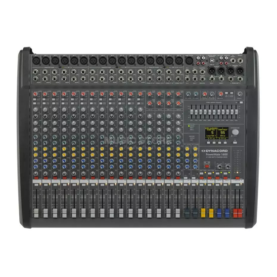
Dynacord PowerMate 1000 Owner's Manual
Power mixer
Hide thumbs
Also See for PowerMate 1000:
- Owner's manual (88 pages) ,
- Bedienungsanleitung (32 pages) ,
- Brochure & specs (8 pages)

Related Manuals for Dynacord PowerMate 1000


Summary of Contents for Dynacord PowerMate 1000
- Page 1 BEDIENUNGSANLEITUNG OWNER’S MANUAL MODE D’EMPLOI P o w e r M a te 1000/1600/2200 POWER MIXER...
-
Page 2: Important Safety Instructions
C O N T E N T S Introduction ..............31 Input/Mono . - Page 3 I N T R O D U C T I O N First of all, we would like to thank you and congratulate you to your purchase of a DYNACORD power mixer. The PowerMate compact power mixers incorporate profound Know-How, based on our research and development in the professional audio market as well as on the inter-communication with our clients, for decades.
- Page 4 I N P U T / M O N O 1. MIC Electronically balanced XLR-type inputs for the connection of low impedance microphones, likewise the ones that are featured in major studio and live mixing consoles. This type of input stage provides extraordinary low noise signal conversion at an extremely low distortion rate (typical <002%) even in the high frequency range.
- Page 5 I N P U T / M O N O 3. INSERT Stereo phone jack with breaker function. The low impedance output is assigned to the tip (send) and the high impedance input (return) is assigned to the ring (body). This jack allows the connection of external compressors, limiters, EQs, de-noisers, etc.
- Page 6 I N P U T / M O N O Sometimes it can be also very effective to combine the LO CUT filter with the VOICING filter. For instance to provide a “thin” voice with more “body”, without getting additional low pitched noise. Whenever the LO CUT is engaged, raising the bass level (LO EQ) provides you with a richer sound, but no additional rumbling or popping noise.
- Page 7 I N P U T / M O N O Adjustments in the MID range are certainly the most effective way to shape the sound. As a matter of fact, determining the correct center frequency is not always as easy as it seems. Here is one method –...
- Page 8 I N P U T / M O N O The AUX3 POST button is engaged (LED is lit): the signal at the AUX3 rotary control is POST FADER – the signal gets split after it passed the channel faders and therefore is affected by their settings.
- Page 9 INPUT/STEREO Since most features of the stereo inputs are virtually identical to the ones of the monaural inputs, we will not discuss their functioning in detail again. Thus, we only point out the differences and ask you to refer to the analogous paragraphs in the first chapter of this owner’s manual. 14.
- Page 10 INPUT/STEREO with pre-programmed channel mapping is to use two adjacent monaural input channels, leaving you the option to place the sound in the final mix via PAN controls. One more tip, in case you desperately need another input and all channels of the PowerMate are already in use: The microphone input and the phone plug-type inputs are electrically totally separated from each other.
- Page 11 INPUT/STEREO 21. BAL The function of the BAL control of the stereo channels is equivalent to the PAN control’s function of the monaural channels. If you turn the rotary control all the way to the right, the right signal is outputted to the right output while the signal of the left channel is muted.
- Page 12 The FOOT SWITCH connector is provided to allow the connection of a foot switch pedal to remote control the FX units’ EFFECT ON/OFF function. If your foot switch features a LED – like the DYNACORD FS 11 does – this indicator will light when the effect is activated.
- Page 13 EFFECT 1/2 29. AUX/FX SEND These rotary controls could also be defined as FX SEND master controls, since they are used to adjust the overall level of the effect mix that you have established using the channel FX send controls. The AUX/FX SEND controls are used to set the input levels of the corresponding FX unit, respectively the levels of the AUX SEND outputs.
- Page 14 AUX 3 Generally, the AUX3 channel is used as monitor bus. Depending on the setting of the AUX3 POST switch, it is also possible to configure the bus for the connection of an additional, external FX unit. 33. AUX3 SEND This output is meant for the connection of an external FX unit, a power amplifier or active stage monitor speaker systems, when the AUX3 bus is used for monitoring purposes.
- Page 15 P H O N E S + M O N O O U T + S T A N D B Y 38. MONO OUTPUT At the monaural output the summed L/R signal of the master is present. It can be used for additional monitoring, side fill and “next door”...
- Page 16 M A S T E R 43. STEREO RETURNS The stereo returns are used to route stereo signals (e. g. of an additional external mixer, FX unit, etc.) to the master output. In case you want to connect a monaural device, please use only the L/MONO return connector.
- Page 17 53. FX1/2 FOOTSW. Phone jack for the connection of a DYNACORD FS11 foot switch, to switch the effect mode of the internal FX units on or off. To accomplish this function, the switches FX1 and FX2 have to be engaged.
- Page 18 M A S T E R 55. POWER AMP STATUS indicators These indicators are to inform you about the momentary operational status of the PowerMate’s internal power amplifier. The POWER ON indicator is always lit when the PowerMate is in operational mode.
- Page 19 M A S T E R 57. 7-BAND EQUALIZER he EQ ON switches activate the 7-band graphic EQs within the Power- Mate’s master channels. The EQ’s insert point is post master fader and pre power amplifier. The EQ is bypassed when the EQ ON switch is not locked in its “ON”...
- Page 20 Even when the maxi- mum input level is overridden, no distortion is heard on the output. The amplifier also incorporates LPN-filters (DYNACORD patent). Together with the 12dB/70Hz LO-CUT filters, the Low Pass Notch filters eliminate transi-...
- Page 21 It also allows the use of high quality speaker cables with a diameter of 4 x 2.5mm . The DYNACORD accessory assortment includes all recommended cables and connectors. WARNING: The speaker output terminals are marked with a symbol “...
- Page 22 2+ and 2- are connected through. This provides you with the possibility to use these cables in an active 2-way system configuration, as well. DYNACORD speaker cables with SPEAKON connectors and all other cables, plugs, and sockets are available at your professional audio dealer.
- Page 23 S T A N D A R D I N S T A L L A T I O N In this chapter we would like to explain to you how to install a typical sound reinforcement system in passive configuration and incorporating stage monitor speakers.
- Page 24 S T A N D A R D I N S T A L L A T I O N Connect the PowerMate’s AUX3 SEND with the external amplifier’s input, using the Balanced NF-cable with the stereo phone plug on one end and the XLR-type connector on the other. Connect all microphones preferably to the monaural inputs of the PowerMate and the keyboards and other comparable sound sources to the rest of the available inputs Pull all faders down and engage the PowerMate’s STANDBY button.
- Page 25 S T A N D A R D I N S T A L L A T I O N 4. Starting from the center position, you can adjust the controls until the sound is to your liking. Please, keep in mind that major alteration of the EQ-setting does not necessarily result in the improvement of the overall sound.
- Page 26 M A S T E R P A T C H B A Y A N D I N S T A L L A T I O N A L T E R N A T I V E S The patch field within the master section is referred to as MASTER PATCHBAY.
- Page 27 M A S T E R P A T C H B A Y A N D I N S T A L L A T I O N A L T E R N A T I V E S 3.
- Page 28 M A S T E R P A T C H B A Y A N D I N S T A L L A T I O N A L T E R N A T I V E S 5.
-
Page 29: Specifications
SPECIFICATIONS Technical Specifications: Mixing desk in rated condition: Unity Gain ( MIC Gain 20 dB ), all faders position 0 dB, all pots in mid position, master fader + 6dB, amplifier rated output power into 8 ohms, one channel driven, unless otherwise specified. Maximum Midband Output Power, 1 kHz, THD 1% PowerMate 1000 PowerMate 1600... - Page 30 B L O C K D I A G R A M...
- Page 31 A B M E S S U N G E N / D I M E N S I O N S Abmessungen/Dimensions (in mm)
- Page 32 • • • • G m b H Hirschberger Ring 45 94315 Straubing Telefon (09421) 706-0 Telefax (09421) 706-265 Änderungen vorbehalten. Subject to change without prior notice. Printed in Germany 05. 06. 2000 /355 029 REV.2 Internet: http:// www.dynacord.de...