
Related Manuals for Dynacord CMS 1000 Owner‘s


Summary of Contents for Dynacord CMS 1000 Owner‘s
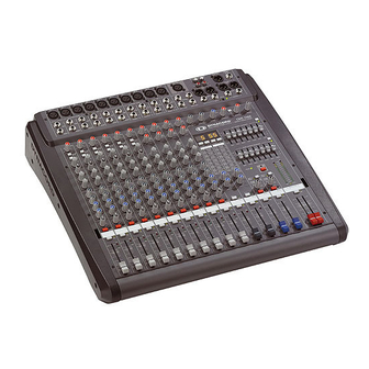
- Page 1 OWNER‘S MANUAL BEDIENUNGSANLEITUNG MODE D‘EMPLOI CMS 1000/1600/2200 COMPACT MIXING SYSTEM...
-
Page 2: Table Of Contents
CONTENTS SAFETY- AND SERVICE INSTRUCTIONS ....... IMPORTANT SAFETY INSTRUCTIONS ....... IMPORTANT SERVICE INSTRUCTIONS ....... DESCRIPTIONS ....... UNPACKING AND WARRANTY ....... INSTALLATION AND CONNECTIONS ....... INPUT MONO ....... INPUT STEREO ....... EFFECT 1/2 ....... AUX3&4 ....... MASTER ....... REAR PANEL ....... CABLING ....... -
Page 3: Safety- And Service Instructions
IMPORTANT SAFETY INSTRUCTIONS The lightning fl ash with arrowhead symbol, within an equilateral triangle is intended to alert the user to the presence of uninsulated „dangerous voltage“ within the product’s enclosure that may be of suffi cient magnitude to constitute a risk of electric shock to persons. The exclamation point within an equilateral triangle is intended to alert the user to the presence of important operating and maintance (servicing) instructions in the... -
Page 4: Descriptions
fi nd the mains supply cord and the warranty card. Please check, whether the warranty registration form is fi lled out correctly. Only when this form is completed, you will be able to apply for warranty claims. DYNACORD grants 36 months of warranty, starting with the date when you received the appliance from your local dealer. -
Page 5: Input Mono
INPUT MONO 1. MIC Electronically balanced XLR-type inputs for the connection of low impedance microphones like the ones featured in state-of-the-art studio and live mixing consoles. This type of input stage provides extraordinary low noise signal conversion at an extremely low distortion rate (typical <0.002%) even in the high frequency range. - Page 6 INPUT MONO 3. INSERT Stereo phone jack with breaker function and with the low impedance output being assigned to the tip (send) and the high impedance input (return) to the ring. This jack allows the connection of external FX units, compressors, limiters, EQs, de-noisers, etc.
- Page 7 INPUT MONO 5. LO CUT 80 Hz When the LO CUT switch is engaged, frequencies below 80 Hz are attenuated (18dB octave slope). In most cases it is good advice to use the LO CUT fi lter with microphone channels, since it effi ciently suppresses popping sounds, rumbling noise and low-frequency feedback.
- Page 8 INPUT MONO Adjustments in the MID frequency range are certainly the most effective way to shape the sound. As a matter of fact, determining the correct center frequency is not always as easy as it seems. Here is one method – amongst others –...
- Page 9 INPUT MONO 10. PAN This control determines the position of the connected sound source within the stereo image. When the control is set at its center position, the audio signal is fed with equal levels to the L and R master busses. The PAN control section is designed to maintain the essential sound pressure level, no matter at what position within the stereo image the PAN control is set to.
-
Page 10: Input Stereo
INPUT STEREO Since most features – AUX controls, input connection and channel faders – of the STEREO INPUTS are virtually identical to the ones of the MONO INPUTS we will not discuss their functioning in detail again. Thus, in the following we only point out the differences and like to ask you to refer to the analogous paragraphs within this owner’s manual describing the MONO INPUTS. - Page 11 INPUT STEREO 18. LINE TRIM Control for matching incoming line level signals to the mixer’s operating level. The total adjustment range is 30dB. Unity gain – no amplifi cation (0 dB) – is achieved at the 0dB mark. The control offers level reduction of –10dB or amplifi...
- Page 12 INPUT STEREO 23. MUTE The MUTE button mutes the input signal post fader, including all AUX sends. PFL and Signal/Peak stay operational. 24. PFL Engaging the PFL button sums the stereophonic audio signal of the corresponding input channel and routes the resulting monaural signal to the headphones bus.
-
Page 13: Effect
FX units’ EFFECT ON/OFF function. If your footswitch features a LED – like the optionally available DYNACORD FS 11 does – this indicator will light when the effect is activated (EFFECT ON). - Page 14 EFFECTS 1/2 29. DISPLAY The display always indicates the actual selected program number of the corresponding FX unit. The display screen is covered with a protective foil to prevent it from being damaged during shipment. Please remove the foil. 30. UP/DOWN The UP/DOWN buttons are for selecting effect presets.
-
Page 15: Aux3&4
AUX3&4 / MASTER Generally, the AUX3/4 channel is used for monitoring purposes. Depending on the setting of the AUX3/4 POST buttons, it is also possible to confi gure the bus for the connection of an additional, external FX unit. 37. AUX3/4 OUT This output provides connection for monitor power amplifi... - Page 16 AUX3&4 / MASTER 42. PFL Through this button you can route the pre AUX3/4 fader signal to the headphones bus. The signal is outputted for listening via the headphones output. The setting of the AUX3/4 fader is not relevant for the signal’s volume (PRE FADER LISTEN). The meter instrument in the master section is simultaneously switched, so that the left LED-chain indicates the level (in dBu) of the actually chosen AUX channel.
-
Page 17: Master
MASTER 46. MASTER LED-DISPLAY The CMS offers two 12-segment LED-chains for indication of left and right channel output levels. The indication range of the LED-meter is 40dB, indicating the levels (in dBu) that are present at the master outputs. The meter’s 0dB mark is referenced to a 0dBu output signal at the mixer output. - Page 18 MASTER 51. MONO OUTPUT At this electronically balanced monaural output the summed L/R master audio signal is present and can be used for additional monitoring, side fi ll and “next door” or Mono-PA applications as well as for the connection of a delay-line or subwoofer. The MONO OUTPUT –...
- Page 19 MONO INPUT. 61. FOOTSWITCH Phone jack for the connection of an optionally available DYNACORD FS11 (110 693) footswitch to switch the effect mode of the internal FX units on or off. To accomplish this function, the FX1 and FX2 ON switches have to be engaged.
-
Page 20: Rear Panel
REAR PANEL POWER Mains switch to turn the CMS on or off. The CMS is operational once the POWER LED lights and outputs are activated through automatic switching of the output relays. Please make sure to set the master faders to their minimum position or engage the STANDBY switch before switching the power on. -
Page 21: Cabling
CABLING Cabling The mains cord comes with the CMS. The quality of all other cables lies in your responsibility. Carefully chosen high quality cables are the best precaution to prevent later problems during live operation. The following wiring alternatives are recommended to provide trouble free operation of your system. -
Page 22: Setting Up A Standard-Pa System
SETTING UP A STANDARD-PA SYSTEM • Place the CMS and all connected appliances in a way that allows their unobstructed operation and connect the mains cord. • Try to locate the best position where you want to place the main PA loudspeaker systems. If possible, the woofers should be placed on the fl... - Page 23 SETTING UP A STANDARD-PA SYSTEM Main Mix Position the master faders in the range between –30dB and –20dB. • Use the channel faders to establish a basic mix, so that individual sound levels relate to each other according to your personal taste.
-
Page 24: Setup Examples
SETUP EXAMPLES Optional Subwoofer Monitoring Setting up a sound reinforcement system with active components. (CMS 1000 + active subwoofer with built-in power amps for top cabinets + two AM12 active monitor speaker systems) - Page 25 SETUP EXAMPLES Monitoring Setting up a sound reinforcement system with active components. (CMS 1600 + four M 18 subwoofer, two M 15 top cabinets + two M 15 used as monitors)
- Page 26 SETUP EXAMPLES Monitoring Setting up a sound reinforcement system with power amps. (CMS 1600 + XA System + two AM12 active monitors)
-
Page 27: Sicherheits- Und Servicehinweise
WICHTIGE SICHERHEITSHINWEISE Das Blitzsymbol innerhalb eines gleichseitigen Drei- ecks soll den Anwender auf nicht isolierte Leitungen und Kontakte im Geräteinneren hinweisen, an denen hohe Spannungen anliegen, die im Fall einer Berührung zu lebensgefährlichen Stromschlägen führen können. Das Ausrufezeichen innerhalb eines gleichseitigen Dreiecks soll den Anwender auf wichtige Bedienungs- sowie Servicehinweise in der zum Gerät gehör- enden Literatur aufmerksam machen. -
Page 28: Beschreibung
Die Compact Mixing Systeme CMS1000, CMS1600 und CMS2200 sind professionelle Mischpulte die aufgrund der vielen integrierten Features, wie Equalizer und Effektgeräte, eine optimierte Komplettlösung für unterschiedlichste Einsatzgebiete darstellen.Die CMS Pulte von DYNACORD können äußerst zeitsparend und einfach aufgebaut werden, da komplizierte Rack-Konfi guration und störanfällige Verkabelung mehrerer Einzelgeräte entfallen.Die eingesetzten, diskret aufgebauten Mikrofon-Preamps zeichnen sich durch hervorragende Audioqualität bei gleichzeitig extrem niedrigen Geräusch- und Klirranteil aus und setzen damit Maßstäbe in der... -
Page 29: Input Mono
INPUT MONO 1. MIC Elektronisch symmetrische XLR-Eingänge zum Anschluß niederohmiger Mikrofone, wie sie auch in großen Studio- oder Livekonsolen verwendet werden. Diese Art der Eingangsstufe ist extrem rausch- und brummarm, darüberhinaus weist sie einen äußerst niedrigen Klirrfaktor (typ.<0.002%), auch bei hohen Frequenzen auf. Sie können hier im Prinzip jedes Mikrofon anstecken, sofern Sie dabei auf die Pin-Belegung entsprechend der untenstehenden Abbildung achten. - Page 30 INPUT MONO 3. INSERT Stereo-Klinkenbuchse mit Unterbrechungs-Funktion, die mit einem niederohmigen Ausgang (Send) an der Spitze (Tip) und einem hochohmigen Eingang (Return) am Ring belegt ist. Diese Buchse ermöglicht das Einschleifen von externen Effektgeräten wie Kompressor, Limiter, EQ, De-Esser, usw. in den jeweiligen Kanal. Der Einschleifpunkt liegt schaltungstechnisch nach der Gain-, LO-Cut- und Voicing Stufe, also noch vor der Klangregelung und dem Kanalschieberegler.
- Page 31 INPUT MONO 5. LO CUT 80 Hz Mit dem LO CUT Schalter können Baßfrequenzen unterhalb 80 Hz mit einer Flankensteilheit von 18 dB pro Oktave unterdrückt werden. Sinnvoll ist die Benutzung des LO CUT-Filters vor allem bei allen Mikrofonanwendungen, wobei hier die Abnahme von Bassdrum oder Bass gesondert zu betrachten ist.
- Page 32 INPUT MONO Im Mittenbereich können Sie am effektivsten Einfl uß auf das Klangbild nehmen, wobei sich aber das Auffi nden der optimalen Arbeitsfrequenz mit dem Frequenzsteller nicht immer ganz einfach gestalltet. Darum hier eine Möglich- keit (unter vielen) wie Sie schnell eine für Ihre Anwendung passende Einstellung des parametrischen EQs fi nden. Einstellhinweis: 1.
- Page 33 INPUT MONO 10. PAN Dieser Regler bestimmt die räumliche Position des Eingangssignals im Stereobild. In Mittelstellung wird das Signal zu gleichen Teilen auf die beiden Summen L und R aufgeteilt. Die PAN-Regler Stufe ist so ausgelegt, dass egal wo Sie den PAN-Regler hindrehen, die Gesamtlautstärke im Stereo Klangbild erhalten bleibt. 11.
-
Page 34: Input Stereo
INPUT STEREO Wir wollen Sie hier bei der Beschreibung des STEREO-INPUTS nicht langweilen, viele Funktionsgruppen wie AUX-Regler, Eingänge, Kanalfader im STEREO INPUT sind identisch zum MONO INPUT aufgebaut und wurden dort bereits ausführlich erklärt. Wir wollen hier nur die wesentlichen Unterschiede herausarbeiten. Ansonsten dürfen wir Sie auf das jeweilige Kapitel beim MONO-INPUT verweisen. - Page 35 INPUT STEREO 18. LINE TRIM Mit diesem Regler wird das Signal an den Line-Eingängen im Stereokanal an den internen Arbeitspegel des Mischpultes angepaßt. Der Regelbereich liegt bei 30 dB. Die Unity Gain Position, also 0 dB Durchgangsverstär- kung, ist hier bei der Markierung 0 dB. Sie können mit diesem Regler das Signal um 10 dB abschwächen bzw. um 20 dB verstärken.
- Page 36 INPUT STEREO 20. AUX / FX Mit diesen Reglern wird das aus L und R summierte Signal POST-FADE auf die AUX/FX-Summenschienen ausgespielt. Die Funktionsweise wurde bereits im INPUT/MONO erläutert. 21. AUX3/4 Legt das aus L und R summierte Signal auf die AUX3- bzw. AUX4 Summenschiene. Dies kann entweder POST- FADER oder PRE-FADER geschehen und wird wie im Monokanal über den AUX PRE/ POST Schalter im Masterbereich ausgewählt.
-
Page 37: Effekt 1/2
Sie bitte auch die FOOTSWITCH-Buchsen. Hier können Sie Fußschalter zur Fernsteuerung der EFFEKT ON/OFF Funktion anschließen. Verfügt Ihr Fußschalter über eine LED z.B. FS11 aus dem DYNACORD Zubehörprogramm, dann wird diese bei EFFEKT ON leuchten. Umstellung der Effekt-Startprogramme Die Effektsektion startet werkseitig mit den Programmen 05/55. Sollten Sie andere Programme bevor- zugen, besteht die Möglichkeit diese im Programmiermodus festzulegen und abzuspeichern. - Page 38 EFFEKT 1/2 29. DISPLAY Das Display zeigt immer die aktuell eingestellte Programmnummer des jeweiligen Effektteils an. Zum Schutz vor Verkratzen ist das Displayglas bei Auslieferung mit einer Folie abgedeckt. Ziehen Sie diese bitte ab. 30. UP/DOWN Mit den UP/DOWN-Tasten werden die Effektprogramme angewählt. Wenn Sie länger auf eine die- ser Tasten drücken, können Sie dadurch eine schnellen Vor- bzw.
-
Page 39: Aux3&4
AUX3/4 Der AUX3/4-Kanalzug wird im wesentlichen zum Monitoring verwendet. Über die AUX3/4 POST Tasten, ist es aber auch möglich hier einen zusätzliches externes Effektgerät zu betreiben. 37. AUX3/4 OUT Hier schließen Sie eine Monitorendstufe bzw. einen Aktivmonitor oder ggf. ein Effektgerät an. Der Pegel an diesem elektronisch symmetrischen Ausgang kann in einem weitem Bereich bis maximal +20 dBu über den AUX3/4 Fader geregelt werden. - Page 40 MASTER 42. PFL Diese Taste gibt das Signal, das vor dem AUX3/4-Fader steht, auf die Kopfhö- rersumme. Sie können dann das AUX3/4-Signal am Kopfhörerausgang abhören. Die Lautstärke am Kopfhörerausgang ist dabei unabhängig vom AUX3/4-Fader (PRE FADER LISTEN). Gleichzeitig bewirkt das Drücken des PFL-Schalters ein Umschalten der Aussteuerungsanzeigen im Master.
-
Page 41: Master
MASTER 46. MASTER LED-DISPLAY Die Aussteuerungsanzeige im CMS besteht aus zwei LED-Ketten für den rechten bzw. linken Kanal mit je 12 LEDs pro Kette. Der Anzeigebereich liegt bei 40 dB und stellt den Pegel in dBu an den Main Outputs dar. D.h. zeigt die Anzeige 0 dB an, so stehen am Mischpultausgang aktuell 0 dBu. - Page 42 MASTER 51. MONO OUTPUT Der elektronisch symmetrische Mono-Ausgang führt das summierte Master L/R Signal, und kann z.B. für Monitoring, Sidefi ll, Nebenraumbeschallung, Mono-PA oder zum Anschluß einer Delay-Line oder Subwoofer verwendet werden. Wie alle XLR Ausgänge des CMS wird auch der MONO OUTPUT über Ausgangsrelais ca.
- Page 43 Vergleichen Sie dazu auch das entsprechende Kapitel beim MONO INPUT. 61. FOOTSWITCH Klinkenbuchsen zum Anschluß eines Fußschalters FS11 (110 693) aus dem DYNACORD Zubehörprogramm. Die eingebauten Effektteile können damit ein- und ausgeschaltet wer- den. Zur Fernsteuerung mittels Fußschalter müssen die Effektgeräte über die FX1 bzw.
-
Page 44: Rückseite
RÜCKSEITE POWER Netzschalter zum Ein- und Ausschalten des Gerätes. Das Gerät ist betriebsbereit, wenn die POWER LED aufl euchtet und die Ausgangs- relais das Signal auf die Ausgänge geschaltet haben. Achten Sie bitte darauf, daß beim Anschalten des Gerätes die beiden Master- Schieberegler geschlossen sind, oder die STANDBY-Taste gedrückt ist. -
Page 45: Verkabelung
AUFBAU EINER STANDARD-PA Verkabelung Das Netzkabel haben Sie mit dem CMS erhalten. Für alle anderen Kabel sind Sie selbst verantwortlich und je sorgfältiger Sie bei der Auswahl der Kabel vorgehen, um so weniger Probleme sind später im Einsatz zu erwarten. Wir können hier nur einige Empfehlungen geben mit denen Sie einen störungsfreien Betrieb Ihres Aufbaus erreichen. -
Page 46: Aufbau Einer Standard-Pa
AUFBAU EINER STANDARD-PA Aufbau • Stellen Sie das CMS und die angeschlossenen Geräte so auf, daß Sie auch im Betrieb leichten Zugriff haben und schließen Sie die Netzkabel an. • Suchen Sie die günstigste Position für Ihre PA-Boxen. Die Bassboxen sollen dabei immer unten am Boden stehen und die Hochton- boxen wenn möglich direkt darüber. - Page 47 AUFBAU EINER STANDARD-PA • Falls Sie an den Monokanälen Instrumente angeschlossen haben, verfahren Sie wie bei der Mikrofoneinstellung beschrieben • Überprüfen Sie nun, ob bei allen nicht benötigten Eingängen die Kanalfader und die Gain- bzw. LINE-TRIM-Regler geschlossen sind. Sie vermeiden dadurch unnötiges Rauschen auf den Ausgängen. Hauptmix •...
-
Page 48: Aufbaubeispiele
AUFBAU BEISPIELE Aufbau einer Beschallungsanlage mit aktiven Komponenten. (CMS 1000 + aktiver Subwoofer mit integrierten Endstufen für Topteile + zwei AM12 Aktivmonitore) - Page 49 AUFBAUBEISPIELE Aufbau einer Beschallungsanlage mit aktiven Komponenten. (CMS 1600 + vier M 18 Subwoofer, zwei M 15 Topt- eile + zwei M 15 als Monitore)
- Page 50 AUFBAUBEISPIELE Aufbau einer Beschallungsanlage mit Endstufen. (CMS 1600 + XA System + zwei AM12 Aktivmonitore)
-
Page 51: Instructions De Sécurité Importantes
INSTRUCTIONS DE SÉCURITÉ IMPORTANTES Le symbole représentant un éclair fl éché dans un triangle équilatéral a pour but d’alerter l’utilisateur de la présence d’une „tension dangereuse“ non isolée à l’intérieur du boîtier, pouvant être d’une force suffi sante pour constituer un risque d’électrocution. -
Page 52: Descriptions
Ce n’est que lorsque vous l’aurez vous-même complétée qu’elle deviendra valable pour toute application de la garantie. DYNACORD offre 36 mois de garantie à partir de la date d’achat/réception auprès de votre revendeur. Nous vous invitons donc à conserver la facture d’achat originale avec le certifi cat de garantie. -
Page 53: Entrée Mono
ENTRÉE MONO 1. MIC Entrées XLR symétrisées électroniquement pour la connexion de microphones à basse impédance, identiques à celles que l’on trouve sur les consoles professionnelles de studio ou de scène. Ce type d’étage d’entrée garantit une conversion du signal à très faible bruit et un taux de distorsion extrêmement bas (typique <0.002%) même dans les fréquences aiguës. - Page 54 ENTRÉE MONO 3. INSERT (Insertion) Embase stéréo à coupure de type „envoi/retour“. La sortie basse impédance est assignée à la pointe de la prise (envoi) et l’entrée haute impédance (retour) est assignée à la bague. Cette embase permet d’insérer des unités d‘effets, compresseurs, limiteurs, égaliseurs (EQ), atténuateurs de bruit (de-noisers) externes etc. dans le parcours du signal de la voie concernée.
- Page 55 ENTRÉE MONO 5. LO CUT 80 Hz (Filtre coupe-bas) Lorsque le bouton LO CUT est activé, les fréquences inférieures à 80 Hz sont atténuées (pente de 18 dB par octave). Dans la plupart des cas, il est recommandé d‘utiliser le fi ltre LO CUT sur les voies des microphones car il supprime effi...
- Page 56 ENTRÉE MONO Les ajustements dans cette bande de fréquences sont certainement le moyen le plus effi cace de façonner le son. En fait, déterminer la fréquence précise à travailler n‘est pas toujours aussi simple qu‘il n‘y paraît. Voici une méthode parmi d‘autres pour trouver rapidement le bon réglage d‘égalisation : Instructions de réglage : Baissez légèrement le fadeur de voie pour éviter tout accrochage.
- Page 57 ENTRÉE MONO 10. PAN Ce contrôle détermine la position de la source sonore dans l‘image stéréo. Lorsque ce potentiomètre est placé au centre, le signal audio est envoyé avec un niveau égal aux bus principaux Let R (Gauche/Droite). La section de contrôle du panoramique est prévue pour maintenir le même niveau de pression sonore, quelle que soit la position du contrôle PAN.
-
Page 58: Entrée Stereo
ENTRÉE STÉRÉO Dans la mesure où la plupart des fonctions – faders d’AUX, potentiomètres et faders de voie – des entrées stéréo sont pratiquement identiques à celles des entrées mono, nous ne les aborderons pas à nouveau en détails. Nous expliquerons donc seulement dans ce qui suit les différences et vous demandons de vous reporter aux paragraphes analogues du manuel qui décrivent les entrées mono. - Page 59 ENTRÉE STÉRÉO 18. LINE TRIM Ces potentiomètres rotatifs permettent de faire correspondre les signaux d‘entrée ligne avec le niveau opérationnel de la CMS. La marge totale d‘ajustement est de 30 dB. Le gain unitaire – pas d‘amplifi cation (0 dB) - s‘obtient sur le repère 0 dB.
- Page 60 ENTRÉE STÉRÉO 23. MUTE Le bouton MUTE atténue entièrement (coupe) le signal d‘entrée „post fader“, ce qui inclue tous les départs AUX. Le PFL et les témoins Signal/Peak restent fonctionnels. 24. PFL Le fait d‘activer le bouton PFL „additionne“ le signal audio stéréo de la voie d’entrée choisie, envoie le signal mono obtenu vers le circuit „casques“...
-
Page 61: Effet
La CMS vous offre également une entrée FOOTSWITCH pour la connexion d’une pédale- interrupteur afi n de commander à distance la fonction EFFECT ON/OFF des processeurs d’effets. Si votre pédale dispose d’un témoin lumineux, comme par exemple la DYNACORD FS 11 optionnelle, il s’allumera lorsque l’effet sera activé (EFFECT ON). - Page 62 EFFETS 1/2 29. AFFICHEUR L’affi cheur indique toujours le numéro de programme actuellement sélectionné pour chacun des processeurs d’effets. L’écran est recouvert d’une feuille de protection pour éviter tout dommage lors du transport. Vous pouvez l’enlever. 30. UP/DOWN Les boutons UP/DOWN permettent de sélectionner les présélections d’effets. Pour faire avancer les numéros de programmes plus rapidement, maintenez le bouton appuyé.
-
Page 63: Aux3&4 Master
AUX3&4 / MASTER Généralement, les voies AUX3/4 sont destinées aux circuits de monitoring/retours de scène. Selon le statut du bouton AUX3/4 POST, il est aussi possible de confi gurer ce circuit pour la connexion d’un processeur d’effet externe supplémentaire. 37. AUX3/4 OUT Cette sortie permet de relier un amplifi... - Page 64 AUX3&4 / MASTER 42. PFL Ce bouton vous permet d’envoyer le signal pré-fader d’AUX3/4 vers le circuit „casques“. Le signal est émis par la sortie physique PHONES pour une écoute au casque. La position du fader d’AUX3/4 n’a aucune infl uence sur le volume du signal.
- Page 65 MASTER 46. ÉCHELLE DE LED MASTER La CMS est équipée d‘une échelle de LED 12 segments pour la surveillance visuelle des niveaux de sortie des signaux généraux gauche (L) et droit (R). La course de ce vu-mètre est de 40 dB, indiquant les niveaux qui sont présents à la sortie générale en dBu.
- Page 66 MASTER 51. MONO OUT Sur cette sortie monophonique, symétrisée électroniquement, le signal audio général cumulé G/D est présent et peur servir à d‘autres applications de sonorisation : monitoring, haut-parleurs latéraux (side-fi ll) et „next door“ ou toutes autres applications de sonorisation mono, mais aussi à...
- Page 67 ENTREE MONO. 61. FOOTSWITCH Prise pour le branchement d‘une pédale DYNACORD FS11 (110 693) disponible en option, permettant d‘activer ou non le mode Effet des unités d‘effets internes. Pour que cela fonctionne, il faut que les sélecteurs FX1 et FX2 soient engagés. Pour télécommander les unités d‘effets à...
-
Page 68: Panneau Arrière
PANNEAU ARRIÈRE POWER Interrupteur secteur pour la mise sous/hors tension de la CMS. La CMS est opérationnelle lorsque le témoin POWER s‘allume et que les sorties de puissance sont activées via la commutation automatique du relais de puissance. Veuillez vous assurer que les faders généraux sont en position minimum ou engager le switch STANDBY avant de procéder à... -
Page 69: Cablage
CABLAGE Câblage Un cordon secteur est fourni avec la CMS. La qualité de tous les autres câbles est sous votre responsabilité. Des câbles de bonne qualité choisis avec soin sont la meilleure des précautions contre de futurs problèmes survenant dans des situations Live. Les choix de câblage suivants sont recommandés pour avoir un fonctionnement sans problème de tout votre système. -
Page 70: Installation D'un Système De Sonorisation
INSTALLATION D‘UN SYSTÈME DE SONORISATION • Placez la CMS et l‘amplifi cateur de puissance externe de manière à pouvoir les faire fonctionner sans gêne et branchez le cordon secteur. • Essayez de repérer le meilleur endroit pour placer les haut-parleurs. Si possible, placez les woofers sur le sol et les enceintes aiguës sur les enceintes basses, sur le même axe vertical. - Page 71 INSTALLATION D‘UN SYSTÈME DE SONORISATION • Réglez l‘égalisation des voies d‘entrée stéréo : Poussez un peu le fader de voie et les faders généraux afi n d’entendre le son provenant des haut-parleurs principaux. Mettez les contrôles EQ en position centrale. Jouez sur la source sonore correspondante.
-
Page 72: Exemples D'installation
EXEMPLES D‘INSTALLATION Optional Subwoofer Monitoring Setting up a sound reinforcement system with active components. (CMS 1000 + active subwoofer with built-in power amps for top cabinets + two AM12 active monitor speaker systems) - Page 73 EXEMPLES D‘INSTALLATION Monitoring Setting up a sound reinforcement system with active components. (CMS 1600 + four M 18 subwoofer, two M 15 top cabinets + two M 15 used as monitors)
- Page 74 EXEMPLES D‘INSTALLATION Monitoring Setting up a sound reinforcement system with power amps. (CMS 1600 + XA System + two AM12 active monitors)
-
Page 75: Specifications
SPECIFICATIONS Technical Specifi cations CMS 1000 / CMS 1600 / CMS 2200 Mixing desk in rated condition, Unity Gain ( MIC Gain 20 dB ), all faders position 0 dB, all pots in mid position, unless otherwise specifi ed. CMS 1000 CMS 1600 CMS 2200 Channels (Mono + Stero) -
Page 76: Block Diagram
BLOCK DIAGRAM... -
Page 77: Dimensions
DIMENSIONS / ABMESSUNGEN... - Page 78 Effect - presets No.: Effect group: Descriptions: Preferably used with: 01 - 10 Reverb Halls bright reverb, concert hall, church, vocals, horn, strings cathedral 11 - 20 Reverb Plates bright plate, no audible piano, guitar, drums, vocals refl ections 21 - 30 Echo/Reverb bright echo/reverb mix specially for “Live”...
- Page 79 Effekt - Presets Nr.: Effektgruppe: Beschreibung: Bevorzugte Anwendung: Nachhall mit brillanter Klangcha- 01 - 10 Reverb Halls rakteristik, Konzertsaal, Kirche, Vocals, Bläser, Strings Kathedrale Plattenhall mit brillanter Klangcha- 11 - 20 Reverb Plates rakteristik ohne wahrnehmbare Piano, Gitarre, Drums, Vocals Refl...
- Page 80 Programmes - Effets No.: Groupe d´effets: Description: Utilisation: 01 - 10 Effets d´halle Brillante reproduction d´halle avec Voix, instruments à vent, instruments à brillant son caractéristique, salle de corde concert, église, cathédrale 11 - 20 Effets de disque Disque en halle avec brillant son Piano, guitare, batterie, voix caractéristique sans réfl...