Dynacord PowerMate 600 Owner's Manual
Power mixer
Hide thumbs
Also See for PowerMate 600:
- Specifications (4 pages) ,
- Brochure & specs (4 pages) ,
- Quick start (4 pages)
Table of Contents
Advertisement
Available languages
Available languages
Advertisement
Table of Contents

Related Manuals for Dynacord PowerMate 600


Summary of Contents for Dynacord PowerMate 600
- Page 1 BEDIENUNGSANLEITUNG OWNER‘S MANUAL MODE D‘EMPLOI PowerMate 600 Power Mixer...
-
Page 2: Table Of Contents
WICHTIGE SICHERHEITSHINWEISE WICHTIGE SERVICEHINWEISE BESCHREIBUNG AUSPACKEN & GARANTIE INSTALLATIONSHINWEISE INPUT MONO INPUT STEREO FX 1/2 AUX / MONO MASTER RÜCKSEITE AUFBAU EINER STANDARD PA MASTER PATCHBAY SPECIFICATIONS / TECHNISCHE DATEN BLOCK DIAGRAM DIMENSIONS / ABMESSUNGEN CONTENTS IMPORTANT SAFETY INSTRUCTIONS IMPORTANT SERVICE INSTRUCTIONS DESCRIPTION UNPACKING AND WARRANTY INSTALLATION... -
Page 3: Wichtige Sicherheitshinweise
Lesen Sie diese Anweisungen. Bewahren Sie die Anleitung sorgsam auf. Beachten Sie sämtliche Warnhinweise. Beachten Sie die Anweisungen. Betreiben Sie dieses Gerät nicht in der Nähe von Wasser. Verwenden Sie zur Reinigung ausschließlich ein trockenes Tuch. Achten Sie darauf, dass die Belüftungsöffnungen nicht versperrt sind. Beachten Sie bei der Installation des Geräts die Anweisungen des Herstellers. -
Page 4: Beschreibung
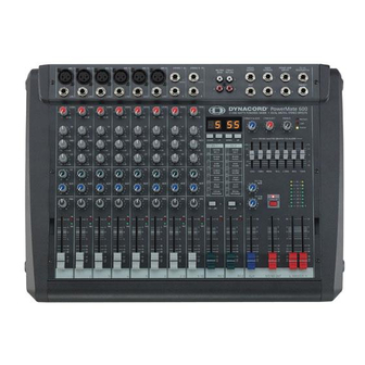
Teile wie Knöpfe und Regler von einer stabilen Schutzhaube abgedeckt sind. Sollten Sie jedoch Ihren PowerMate 600 lieber im Rack plazieren, kein Problem, die Kunststoffseitenteile können sehr einfach durch Me- tall-Rackwinkel ersetzt werden. Mit seiner großen Anzahl von Funktionen, hohen Dynamik, rauscharmen Design, dem 24bit-Dual-Stereo-Effektteil und der starken Endstufe ist der PowerMate universell einsetzbar. -
Page 5: Input Mono
INPUT MONO 1. MIC Elektronisch symmetrische XLR-Eingänge, ( wie sie auch in großen Studio- oder Livekon- solen verwendet werden) zum Anschluss niederohmiger Mikrofone. Die Eingangsstufe ist extrem rausch- und brummarm, dar- überhinaus weist sie einen äußerst niedrigen Klirrfaktor (typ.<0.002%), auch bei hohen Frequenzen auf. Sie können hier im Prinzip jedes Mikrofon anstecken, sofern Sie dabei auf die Pin-Belegung entsprechend der nebenstehenden Ab- bildung achten. - Page 6 3. GAIN Regler zum Abgleich der Eingangsempfindlichkeit des MIC-bzw. LINE-Eingangs, wobei die an- kommenden Signale optimal auf den internen Arbeitspegel des Mischpultes angepasst werden. Durch eine gewissenhafte Einpegelung des Signals können Sie den Signal-Rauschabstand optimieren und die hervorragenden Audioeigenschaften des PowerMate im vollen Umfang nutzen.
- Page 7 INPUT MONO 5. FX Mit den FX-Regler können Sie das jeweilige Eingangssignal den eingebauten Digital-Ef- fektgeräten FX1 und FX2 stufenlos zumischen. Das Original-Signal wird “post-fade” also nach dem Kanalschieberegler abgegriffen und ist somit von dessen Einstellung abhängig. Bei der Einstellung des Effektanteils gehen Sie immer von Regler in Mittelstellung aus und gleichen je nach gewünschter Intensität ab.
-
Page 8: Input Stereo
INPUT STEREO 10. STEREO INPUT L / MONO R Elektronisch symmetrische Eingänge speziell für Stereo Instrumente und Geräte. Sie kön- nen hier alle elektronische Instrumente wie Keyboard, Drum-Computer, Gitarre und Bass mit aktiver Elektronik sowie alle anderen hochpegeligen Stereo-Signalquellen wie zu- sätzliche Mischpulte, Effektgerät, CD-Player usw. - Page 9 INPUT STEREO 13. FX Mit diesem Regler wird das aus L und R summierte Signal “post-fade” auf die FX- Summenschienen ausgespielt. Die generelle Funktionsweise wurde bereits im INPUT/ MONO erläutert. 14. AUX Legt das aus L und R summierte Signal auf die AUX-Summenschiene (siehe auch INPUT/MONO).
- Page 10 Sie einen Fußschalter zur Fernsteuerung der EFFEKT ON/OFF Funk- tion anschließen. Verfügt Ihr Fußschalter über eine LED, z.B. FS11 aus dem DYNACORD Zubehörprogramm, dann wird diese bei EFFEKT ON leuchten. Umstellung der Effekt-Startprogramme Die Effektsektion startet werkseitig mit den Programmen 05/55. Sollten Sie an- dere Programme bevorzugen, besteht die Möglichkeit diese im Programmier-...
- Page 11 19. UP/DOWN Mit den UP/DOWN-Tasten werden die Effektprogramme angewählt. Wenn Sie länger auf eine dieser Tasten drücken, können Sie dadurch eine schnel- len Vor- bzw. Rücklauf der Programmnummern erzeugen. 20. FX ON Durch Drücken des Schalter wird das interne Effektteil eingeschaltet, die grüne LED leuchtet.
-
Page 12: Aux/Mono
AUX/MONO Der AUX-Kanalzug wird im wesentlichen zum Monitoring verwendet. 23. AUX SEND Hier schließen Sie entweder eine Monitorendstufe oder einen Aktivmonitor an. Der Pegel an dieser Buchse kann in einem weitem Bereich bis maximal +20 dBu über den AUX Fader geregelt werden. Die Ausgangsbeschaltung ist in Groundsensing-Technik ausgeführt, um auch bei langen Leitungen einer etwaigen Brummeinstreuung entge- genzuwirken. - Page 13 EFFEKT 1/2 29. PHONES-Buchse STEREO-Klinkenbuchse für Kopfhörer von 32 - 600 Ohm. Hier kann das “pre-fade” Mas- tersignal abgehört werden. 30. PHONES-Regler Mit diesem Regler wird die Lautstärke am Kopfhörer eingestellt. ACHTUNG: Drehen Sie den Regler immer ganz zurück, bevor Sie den Kopfhörer anschließen. 31.
-
Page 14: Master
38. STATUS ANZEIGE Diese Anzeigen informieren Sie über den aktuellen Zu- stand des Leistungsverstärkers im PowerMate. PROTECT leuchtet dann auf, wenn eine der um- fangreichen Schutzschaltung wie Übertemperatur-, Hochfrequenz-, Gleichspannungs-, oder SOAR-Schutz- schaltung im Leistungsverstärker aktiv ist. Um die Leis- tungsverstärker vor Zerstörung zu schützen, werden im Protect Mode die Lautsprecher abgeschalten und der Eingang der Endstufe kurzgeschlossen. - Page 15 MASTER Die Frequenzbereiche und Regelcharakteristik der ein- zelnen EQ-Fader ist sehr praxisorientiert ausgelegt. Wollen Sie einen strahlenden, klaren Sound und z.B. den Schlagzeugbecken mehr Durchsetzungskraft verleihen, so heben Sie im Bereich von 12kHz- bzw. 6 kHz etwas an. Ist der Sound sehr nasal und mittenbetont, so senken Sie im Mittenfrequenzbereich leicht ab.
-
Page 16: Rückseite
RÜCKSEITE SPEAKER OUTPUTS RIGHT / LEFT Der PowerMate 600 ist mit professionellen SPEAKON- Hochlaststeckverbindungen ausgestattet. Diese mecha- nisch und elektrisch sichere Verbindung wird allen Sicher- heitsanforderungen gerecht und erlaubt die Verwendung von Hochleistungslautsprecherkabeln von bis zu 4 x 2,5mm Querschnitt. -
Page 17: Aufbau Einer Standard Pa
Sie dabei aber gleich ein 4 adriges Kabel verwenden sollten, an dem Sie auch 2+ und 2- durchver- binden, da diese Kabel dann auch in aktiv 2-Weg-Systemen verwendet werden können. Lautsprecherkabel mit SPEAKON Steckern können Sie über den Fachhandel aus dem DYNACORD-Zubehörprogramm beziehen. Auch alle anderen Kabel und Stecker sind dort erhältlich. - Page 18 Im folgenden wollen wir erklären, wie Sie mit dem PowerMate ein passiv Standard-PA mit Monitorsystem aufbau- en und einstellen. An PA-Equipment haben wir vorgesehen: 1 PowerMate600-2 1 Monitorendstufe z.B. 2x250W 2 Hochtonboxen z.B. 12“ 3-Weg 2 Bassboxen z.B. 15“ 2 Hochständer oder 2 Zwischenstangen 2 Monitorboxen 4 SPEAKON-Kabel 8m, 2 SPEAKON-Kabel 2m 1 NF-Kabel Stereoklinke-XLR Stecker...
- Page 19 • Schließen Sie nun alle Mikrofone bevorzugt an den Monokanälen, und die Instrumente usw. an den verbleibenden Kanälen des PowerMate an. • Ziehen Sie alle Fader nach unten und drücken die STANDBY-Taste am PowerMate. Sie verhindern dadurch etwaiges Rückkopplungspfeifen beim Einschalten. •...
- Page 20 Monitormix • AUX-Fader im Masterbereich zurückziehen • Alle AUX-Regler in den belegten Eingangskanälen in Mittelstellung drehen. • AUX-Fader vorsichtig aufziehen. • Ziehen Sie den AUX-Fader nur soweit auf wie nötig, um auch bei ungünstiger Mikrofonposition noch genügend Reserve zur Koppelgrenze zu haben. •...
- Page 21 OWNER‘S MANUAL PowerMate 600 Power Mixer...
-
Page 22: Master Patchbay
IMPORTANT SAFETY INSTRUCTIONS IMPORTANT SERVICE INSTRUCTIONS DESCRIPTION UNPACKING AND WARRANTY INSTALLATION INPUT MONO INPUT STEREO EFFECT 1/2 AUX / MONO MASTER REAR PANEL SETTING UP A STANDARD PA-SYSTEM ... MASTER PATCHBAY SPECIFICATIONS / TECHNISCHE DATEN BLOCK DIAGRAM DIMENSIONS / ABMESSUNGEN... -
Page 23: Important Safety Instructions
IMPORTANT SAFETY INSTRUCTIONS Read these instructions. Keep these instructions. Heed all warnings. Follow all instructions. Do not use this apparatus near water. Clean only with a dry cloth. Do not block any ventilation openings. Install in accordance with the manufacture’s instructions. Do not install near heat sources such as radiators, heat registers, stoves, or other apparatus (including amplifiers) that produce heat. -
Page 24: Description
DESCRIPTION First of all, we would like to thank you and congratulate you to your purchase of a DYNACORD power mixer. The PowerMate compact power mixers incorporate profound know-how, based on our research, development and inter-communication with our customers in the professional audio market, for decades. With a PowerMate you own a power mixer that offers a wide range of functionality in a very compact frame. -
Page 25: Input Mono
INPUT MONO 1. MIC Electronically balanced XLR-type inputs for the connection of low impedance microphones, likewise the ones that are featured in major studio and live mixing consoles. This type of input stage provides extraordi- nary low noise signal conversion at an extremely low distor- tion rate (typical .002%) even in the high frequency range. - Page 26 3. GAIN Rotary control to adjust the MIC or LINE inputs’ sensitivity. These controls let you optimally adjust the incoming signals to the mixer’s internal operation level. Cautious adjusting of- fers the benefits of an improved S/N-ration and provides you with the full bandwidth of the PowerMate’s outstanding sound capabilities.
- Page 27 INPUT MONO 5. FX The FX-controls are used to adjust individual amounts of the channel signals to be routed to the FX1 and/or the FX2 unit. The split point of the “dry” signal is POST FADE or in other words: the fader setting also influences the signal that is fed to the FX units.Before you start to establish the effect mix, these controls should be set at their center position.
-
Page 28: Input Stereo
INPUT STEREO 10. STEREO INPUT L/MONO R Electronically balanced inputs for the connection of musical instruments with stereo out- put, like keyboards, drum computers, E-guitars and E-basses with an active output as well as any equivalent sound source that provides a high level output; like additional mixing consoles, effect units, compact disc players, etc. - Page 29 INPUT STEREO 13. FX These controls determine the amount of the summed L and R signals that are sent to the FX bus. The signal split is POST FADER. For more details on the functioning of these controls, please refer to the INPUT/MONO section of this owner’s manual. 14.
- Page 30 FX units’ EFFECT ON/ OFF function. If your footswitch features a LED – like the optionally available DYNACORD FS 11 does – this indicator will light when the effect is activated (EFFECT ON).
- Page 31 19 . UP/DOWN The UP/DOWN buttons are for selecting effect presets. Keeping a button pressed continuously lets you step quickly through the program numbers. 20. FX ON This switch switches an internal FX unit on and the green LED lights. Please keep in mind that you can also use an external footswitch for the switching of the FX unit.
-
Page 32: Aux/Mono
AUX/MONO Generally, the AUX channel is used as monitor bus. 23. AUX SEND This output serves for the connection of a monitoring power amplifier or active stage monitors. Using the AUX fader, the output level can be adjusted in a wide range up to +20dBu. - Page 33 POWER AMP INPUTS. 37. FX1/2 FOOTSWITCH Phone jack for the connection of a DYNACORD FS11 foot switch, to switch the internal FX units on or off. To accomplish this function, the switches FX1 and FX2 have to be...
-
Page 34: Master
38. STATUS INDICATOR These indicators are to inform you about the momentary operational status of the PowerMate’s internal power amplifier. The PROTECT indicator lights when one of the power amplifier’s extensive protection functions – against thermal overload, HF-induction, DC at the outputs, and SOAR-protection –... - Page 35 MASTER The frequency ranges as well as the characteristics of the EQ-faders are designed very praxis-oriented. In case you intend to have a clear and highly intelligible sound, which, as a side effect, provides the cymbals with more crisp, you should increase the level setting of the 6 kHz or 12 kHz band a bit.
-
Page 36: Rear Panel
SPEAKER OUTPUTS RIGHT / LEFT The PowerMate 600 provides professional SPEAKON con- nectors, offering an electrical and mechanical secure con- nection which complies to all security regulations allowing the use of high quality speaker cables with a diameter of up to 4 x 2.5mm2. - Page 37 We recommend the use 4-wire cables where also the pins 2+ and 2- are connected through. This provides you with the possibility to use these cables in an active 2-way system configuration, as well. DYNACORD speaker cables with SPEAKON connectors and all other cables, plugs, and sockets are available at your professional audio dealer.
- Page 38 In the following we would like to explain to you how to install a typical sound reinforcement system in passive con- figuration with incorporated stage monitors. The necessary equipment is: PowerMate 600-2 Power amplifier for the monitor signal – for i. e. 2x250 watts Hi cabinets –...
- Page 39 • Connect all microphones – preferably to the monaural inputs of the PowerMate – and the keyboards and other comparable audio signal sources to the rest of the available inputs. • Pull all faders down and engage the PowerMate’s STANDBY button. This measure prevents unwanted feedback noise when switching the equipment on.
- Page 40 MONITOR MIX • Lower the setting of the AUX fader within the master section. • Adjust the AUX faders of all input channels that are momentarily in use at their center position. • Push the AUX fader up as far as absolutely necessary. In this way you have enough headroom before feedback, even when the microphone are not optimally positioned.
- Page 41 MODE D‘EMPLOI PowerMate 600 Power Mixer...
- Page 42 INSTRUCTIONS DE SÉCURITÉ IMPORTANTES INSTRUCTIONS DE RÉPARATION IMPORTANTES INTRODUCTION DÉBALLAGE ET GARANTIE INSTALLATION ET BRANCHEMENTS INPUT MONO INPUT STEREO EFFETS 1/2 AUX3/4 MASTER PANNEAU ARRIÈRE INSTALLATION SONORISATION STANDARD SPECIFICATIONS BLOCK DIAGRAM DIMENSIONS ... 43 ... 43 ... 44 ... 44 ...
-
Page 43: Instructions De Sécurité Importantes
INSTRUCTIONS DE SÉCURITÉ IMPORTANTES Veuillez lire ces instructions. Conservez ces instructions. Respectez toutes les consignes de sécurité. Suivez scrupuleusement toutes les instructions. N’utilisez pas cet appareil près d’un point d’eau. Utilisez uniquement un chiffon sec pour le nettoyer. N’obstruez aucune des ouïes de ventilation. Installez-le en respectant les instructions du fabricant. Ne l’installez pas près de sources de chaleur tels que radiateurs, panneaux chauffants, étuves, ou autres appareils produisant de la chaleur (dont les amplificateurs). -
Page 44: Introduction
De plus, si vous préférez placer votre PowerMate 600 dans un rack 19“, pas de problème ! Tout ce que vous aurez à faire sera de remplacer les montants latéraux en plastique par des oreilles de rack en métal. - Page 45 ENTRÉE MONO 1. MIC Entrées XLR symétrisées électroniquement pour la connexion de microphones à basse impédance, identiques à celles que l’on trouve sur les consoles professionnelles de studio ou de scène. Ce type d’étage d’entrée garantit une conversion du signal à très faible bruit et un taux de distorsion extrêmement bas (typique <0.002%) même dans les fréquences aiguës.
- Page 46 3. GAIN Potentiomètre rotatif pour ajuster la sensibilité des entrées MIC/LINE. Ce potentiomètre vous permet de faire correspondre au mieux les signaux entrants avec le niveau de fonctionnement interne de la console. Un réglage précis permet de bénéficier du meilleur rapport signal/bruit et de toute l’incroyable dynamique qu’offre la PowerMate.
- Page 47 ENTRÉE MONO 5. FX (Effets) Les contrôles FX permettent, pour chaque voie, de définir la quantité de signal à envoyer aux processeurs d’effets intégrés FX1 ou FX2. Le trajet du signal passe après le fader de volume (post-fader) de façon à ce que les réglages du fader influencent aussi la quantité de signal envoyé...
- Page 48 ENTRÉE STEREO 10. STEREO INPUT L/MONO R Entrées symétriques pour la connexion d’instruments de musique à sortie stéréo comme les claviers, les boites à rythmes, les guitares et basses électriques à sortie active ainsi que toute autre source sonore équivalente à haut niveau de sortie comme les tables de mixage additionnelles, les processeurs d’effets, les lecteurs CD etc.
- Page 49 ENTRÉE STEREO 13. FX Ces contrôles déterminent la quantité de signal gauche/droite „cumulée“ qui sera envoyée (Post-fader) au circuit FX. Pour plus de détails sur le fonctionnement de ces contrôles, veuillez vous reporter à la section INPUT/MONO de ce mode d‘emploi. 14.
- Page 50 à distance la fonction EFFECT ON/OFF des processeurs d’effets. Si votre pédale dispose d’un témoin lumineux, comme par exemple la DYNACORD FS 11 optionnelle, il s’allumera lorsque l’effet sera activé (EFFECT ON). Changer les effets de démarrage Par défaut, les processeurs d’effets proposent les programmes 5 et 55.
- Page 51 18. AFFICHEUR L’afficheur indique toujours le numéro de programme actuellement sélectionné pour chacun des processeurs d’effets. L’écran est recouvert d’une feuille de protection pour éviter tout dommage lors du transport. Vous pouvez l’enlever. 19. UP/DOWN Les boutons UP/DOWN permettent de sélectionner les présélections d’effets. Pour faire avancer les numéros de programmes plus rapidement, maintenez le bouton appuyé.
- Page 52 AUX/MONO Généralement la voie AUX est affectée au circuit des retours. 23. AUX SEND Cette sortie permet de relier un amplificateur de puissance ou encore un système de retours de scène amplifiés. Le fader AUX permet de régler le niveau de sortie avec une grande marge et jusqu’à...
- Page 53 PowerMate via les entrées POWER AMP INPUTS. 37. FX1/2 FOOTSWITCH Prise pour le branchement d‘une pédale DYNACORD FS11, permettant d‘activer ou non les unités d‘effets internes. Pour que cela fonctionne, il faut que les sélecteurs FX1 et FX2 soient engagés.
- Page 54 38. TÉMOINS INDICATEURS D‘ÉTAT Ils vous informent de l‘état de fonctionnement actuel de l‘amplificateur de puissance interne de la PowerMate. Le témoin PROTECT s‘allume si un des nombreux circuits de protection contre la surchauffe, l‘induction HF, la présence de composantes DC en sortie et le système de protection SOAR, s’est activé.
- Page 55 MASTER Les bandes de fréquences ainsi que les caractéristiques des faders d‘EQ sont très orientés „pratique“. Si vous désirez obtenir un son clair et très intelligible, ce qui donnera également des cymbales plus précises, vous devez pousser légèrement le niveau des bandes 6 kHz ou 12 kHz.
- Page 56 à toutes les normes de sécurité et autorisant l’usage de câbles de haut-parleur de qualité, ayant un diamètre de 4 x 2,5 mm L’assortiment des accessoires DYNACORD inclut tous les câbles et connecteurs recommandés. POWER Interrupteur secteur pour la mise sous/hors tension de la PowerMate.
- Page 57 à 4 brins où les broches 2+ et 2– sont aussi connectées. Ceci donne la possibilité d’utiliser également ces câbles dans une configuration active à deux voies. L’assortiment des accessoires DYNACORD comprend différents câbles de haut-parleurs munis de connecteurs SPEAKON et tous les autres câbles, prises et embases sont disponibles auprès de votre revendeur local de matériel audio professionnel.
- Page 58 Dans ce qui suit, nous allons expliquer comment installer un système de sonorisation typique dans une configuration passive. Les équipements nécessaires sont les suivants :` PowerMate 1000 amplificateur de puissance, par ex. 2x250 watts enceintes d’aigus, par ex. HP 12» 3 voies enceintes basses, par ex.
- Page 59 • Connectez tous les microphones de préférence aux entrées mono de la PowerMate et les claviers et autres sources sonores du même type sur le reste des entrées disponibles. • Baissez tous les faders au minimum et engagez le bouton STANDBY de la PowerMate pour éviter tout accrochage intempestif.
- Page 60 MIXAGE DU CIRCUIT MONITEUR • Baissez le fader AUX situé dans la section générale. • Réglez les faders AUX de toutes les voies d’entrée utilisées en position centrale. • Poussez le fader AUX autant que possible. Vous aurrez ainsi suffisamment de réserve avant que ne se produise un accrochage pendant le spectacle, même si certains microphones sont placés dans des positions désavantageuses.
-
Page 61: Specifications
Technical Specifications PowerMate600 Mixing desk in rated condition, Unity Gain (MIC Gain 20 dB), all faders position 0 dB, all pots in mid position, master fader + 6dB, amplifier rated output power into 8 Ohms, dual channel, unless otherwise specified. Maximum Midband Output Power, 1 kHz, THD=1%, Dual Channel into 4 Ohms into 8 Ohms... -
Page 62: Block Diagram
BLOCK DIAGRAM... -
Page 63: Dimensions
DIMENSIONS... - Page 64 Bosch Communications Systems Americas–Headquarter Americas Telex Communications, Inc. 12000 Portland Ave South, Burnsville, MN 55337, USA USA–Ph: 1-800-392-3497 Fax: 1-800-955-6831 Canada–Ph: 1-866-505-5551 Fax: 1-866-336-8467 Latin America–Ph: 1-952-887-5532 Fax: 1-952-736-4212 EVI AUDIO GmbH www.eviaudio.de Europe, Africa & Middle-East Headquarter EAME EVI Audio GmbH Hirschberger Ring 45, D-94315, Straubing, Germany Phone: +49 9421 706-0,...