Table of Contents
Advertisement
NOTE:
Please read all instructions
carefully before using this
product
Table of Contents
Safety Notice
Hardware Identifier
Assembly Instruction
Parts List
Resistance Chart
Warranty
Ordering Parts
Model
MD-1559
Retain This
Manual for
Reference
09-13-06
OWNER'S
MANUAL
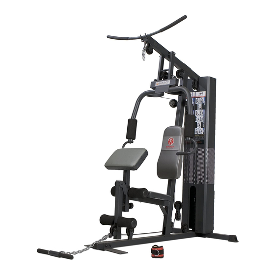
MARCY DIAMOND ELITE
HOME GYM
14777 DON JULIAN RD., CITY OF INDUSTRY, CA 91746
Tel: (800) 999-8899 Fax: (626) 961-9966
www.impex-fitness.com
info@impex-fitness.com
MD-1559
®
IMPEX
INC.
Advertisement
Table of Contents

Related Manuals for Impex MARCY DIAMOND MD-1559


Summary of Contents for Impex MARCY DIAMOND MD-1559
- Page 1 Table of Contents Safety Notice Hardware Identifier Assembly Instruction Parts List Resistance Chart Warranty Ordering Parts Model MD-1559 Retain This Manual for Reference 09-13-06 OWNER'S MANUAL MARCY DIAMOND ELITE HOME GYM MD-1559 IMPEX 14777 DON JULIAN RD., CITY OF INDUSTRY, CA 91746 Tel: (800) 999-8899 Fax: (626) 961-9966 www.impex-fitness.com...
-
Page 2: Table Of Contents
RESISTANCE CHART…………...………. 19 WARRANTY...…………. 20 ORDERING PARTS...………… 20 BEFORE YOU BEGIN Thank you for selecting the MARCY DIAMOND MD-1559 HOME GYM by ® IMPEX INC. For your safety and benefit, read this manual carefully before using the machine. As a manufacturer, we are committed to provide you complete customer satisfaction. -
Page 3: Important Safety Notices
PHYSICIAN. THIS IS ESPECIALLY IMPORTANT FOR INDIVIDUALS OVER THE AGE OF 35 OR PERSONS WITH PRE-EXISTING HEALTH PROBLEMS. READ ALL INSTRUCTIONS BEFORE USING ANY FITNESS EQUIPMENT. IMPEX INC. ASSUMES NO RESPONSIBILITY FOR PERSONAL INJURY OR PROPERTY DAMAGE SUSTAINED BY OR THROUGH THE USE OF THIS PRODUCT. -
Page 4: Warning Label Replacement
WARNING LABEL REPLACEMENT The warning labels shown here have been placed on the Rear Base Frame and Upper Frame. If the labels are missing or illegible, please call customer service at 1-800-888-8899 for replacements. Apply the labels in the location shown. -
Page 5: Hardware Pack
HARDWARE PACK... - Page 6 HARDWARE PACK...
- Page 7 HARDWARE PACK...
-
Page 8: Assembly Instructions
ASSEMBLY INSTRUCTION Tools Required Assembling the Machine: Two Adjustable Wrenches, two Allen Wrenches, and one Philips Screwdriver. NOTE: It is strongly recommended this machine to be assembled by two or more people to avoid possible injury. STEP 1 (See Diagram 1) A.) Attach the Front Vertical Frame (#3) to the Main Base Frame (#8). - Page 9 STEP 2 (See Diagram 2) A.) Slide the 14 Weight Plates (#29) onto the Guide Rods (#20). Make sure the groove on the Plate all need to face up and toward front of the machine. Align the holes of the Weight Plates.
- Page 10 STEP 3 (See Diagram 3) A.) Attach the Front Press Base (#11) to the Upper Frame (#4). Secure it with one Long Axle (#43), two Ø ¾” Washers (#80), and two M10 Aircraft Nuts (#82). B.) Attach the Right Butterfly (#6) to the Front Press Base. Secure it with one M6 x 1 3/8” Allen Bolt (#75), Lock Ring (#37), and M6 Aircraft Nut (#83).
- Page 11 STEP 4 (See Diagram 4) A.) Attach the Main Seat Support (#1) to the Front Vertical Frame (#3). Secure it with two M10 x 3 ½” Carriage Bolts (#76), one 4 ¾” x 2” Bracket (#24), two M10 Aircraft Nuts (#82). B.) Attach the Leg Developer (#7) to the bracket on the Main Seat Support.
- Page 12 CABLE LOOP DIAGRAM...
- Page 13 STEP 5 (See Diagram 5 & Cable Loop Diagram) A.) Attach the 134” Upper Cable (#31) to the open bracket under the front of the Upper Frame (#4). Note: The Ball Stopper on the cable should be underneath the Frame. B.) Attach a Pulley (#60) to the open bracket.
- Page 14 DIAGRAM 5...
- Page 15 STEP 6 (See Diagram 6 & Cable Loop Diagram) A.) Attach one end of the 119” Butterfly Cable (#33) to the hook on the Right Butterfly (#6). B.) Draw the Cable to the right Swivel Pulley Bracket (#18). C.) Attach a Pulley to the bracket. Secure it with one M10 x 1 ¾” Allen Bolt (#69), two Ø ¾” Washers (#80), and one M10 Aircraft Nut (#82).
- Page 16 STEP 7 (See Diagram 7 & Cable Loop Diagram) A.) Attach the 129” Lower Cable (#32) to the open bracket on the bottom of the Leg Developer (#7). B.) Attach a Pulley to the bracket. Secure it with one M10 x 1 ¾” Allen Bolt (#69), two Ø ¾”...
- Page 17 DIAGRAM 7...
- Page 18 STEP 8 (See Diagram 8) A.) Attach a Short Chain (#46) to the Upper Cable (#31) by using a C-clip (#50). Attach the Lat Bar (#14) to the Chain by using another C-clip. Adjust the length of the Chain to obtain desired Lat Bar exercise. B.) Attach a Long Chain (#45) to the Lower Cable (#32) by using a C-clip (#50).
-
Page 19: Parts List
PARTS LIST KEY NO. DESCRIPTION Main Seat Support Rear Base Frame Front Vertical Frame Upper Frame Left Butterfly Right Butterfly Leg Developer Main Base Frame Butterfly Pulley Bracket Arm Curl Stand Front Press Base Front Press Handle Selector Rod Lat Bar Arm Curl Handle Double Floating Pulley Bracket Crossed Double Floating Pulley Bracket1... -
Page 21: Warranty
IMPEX. IMPEX is not responsible or liable for indirect, special or consequential damages arising out of or in connection with the use or performance of the product or other damages with respect to any economic loss, loss of property, loss of revenues or profits, loss of enjoyments or use, costs of removal, installation or other consequential damages or whatsoever natures.