Table of Contents
Advertisement
NOTE:
Please read all instructions
carefully before using this
product
Table of Contents
Safety Notice
Hardware Identifier
Assembly Instruction
Parts List
Warranty
Ordering Parts
Model
MD-9010
Retain This
Manual for
Reference
08-08-06
OWNER'S
MANUAL
MARCY
SMITH MACHINE
14777 DON JULIAN RD., CITY OF INDUSTRY, CA 91746
Tel: (800) 999-8899 Fax: (626) 961-9966
www.impex-fitness.com
info@impex-fitness.com
®
DIAMOND ELITE
MD-9010
®
IMPEX
INC.
Advertisement
Table of Contents

Related Manuals for Impex MARCY MD-9010


Summary of Contents for Impex MARCY MD-9010
-
Page 1: Impex Inc
Please read all instructions carefully before using this product Table of Contents Safety Notice Hardware Identifier Assembly Instruction Parts List Warranty Ordering Parts Model MD-9010 Retain This Manual for Reference 08-08-06 OWNER'S MANUAL ® MARCY DIAMOND ELITE SMITH MACHINE MD-9010 IMPEX 14777 DON JULIAN RD., CITY OF INDUSTRY, CA 91746... -
Page 2: Table Of Contents
Toll-Free Customer Service Number Mon. - Fri. 9 a.m. - 5 p.m. PST www.impex-fitness.com info@impex-fitness.com ® DIAMOND ELITE MD-9010 by IMPEX To avoid unnecessary delays, please call our Our Customer Service Agents will 1-800-999-8899 ®... -
Page 3: Important Safety Notices
PHYSICIAN. THIS IS ESPECIALLY IMPORTANT FOR INDIVIDUALS OVER THE AGE OF 35 OR PERSONS WITH PRE-EXISTING HEALTH PROBLEMS. INSTRUCTIONS BEFORE USING ANY FITNESS EQUIPMENT. ASSUMES NO RESPONSIBILITY FOR PERSONAL INJURY OR PROPERTY DAMAGE SUSTAINED BY OR THROUGH THE USE OF THIS PRODUCT. SAVE THESE INSTRUCTIONS. READ ALL IMPEX INC. -
Page 4: Warning Label Placement
WARNING LABEL PLACEMENT The warning labels shown here have been placed on the Rear Base, Rear Stabilizer, and Upper Frame. If the labels are missing or illegible, please call customer service at 1-800-888-8899 for replacements. Apply the labels in the location shown. -
Page 5: Smith Machine Hardware Pack
SMITH MACHINE HARDWARE PACK... - Page 6 SMITH MACHINE HARDWARE PACK...
-
Page 7: Smith Machine Assembly Instructions
SMITH MACHINE ASSEMBLY INSTRUCTION Tools Required Assembling the Machine: Two Adjustable Wrenches and Allen Wrenches. NOTE: It is strongly recommended two or more people assembling this machine to avoid possible injury. STEP 1 (See Diagram 1) A.) Connect the two Base Frames (#1) by a Cross Brace (#2) in the mid-span. Secure each end of The Cross Brace with two M10 x 3 ½”... - Page 8 STEP 2 (See Diagram 2) A.) Attach a Front Vertical Frame (#3) to the right Base Frame (#1). Secure it with two M10 x 3” Carriage Bolts (#76), one 5 1/8” x 2 ¾” Bracket (#34), two Ø ¾” Washers (#66), and two M10 Aircraft Nuts (#86).
-
Page 9: Diagram 2
DIAGRAM 2... - Page 10 STEP 3 (See Diagram 3) A.) Attach the Rear Vertical Beam (#6) to the top of the Cross Brace (#2). Attach the Weight Glide Base (#8) to the Cross Brace from the Bottom. Align the holes. Secure them with two M10 x 3” Carriage Bolts (#76), Ø ¾” Washers (#66), and M10 Aircraft Nuts (#86). B.) Attach the Pulley Support Frame (#97) to the Rear Vertical Beam.
- Page 11 STEP 4 (See Diagram 4) A.) Attach the Weight Glide Post (#7) onto the Weight Glide Base (#8). Secure it with four M10 x 1” Carriage Bolts (#74), Ø ¾” Washers (#66) and M10 Aircraft Nuts (#86). B.) Slide the Sliding Weight Post (#14) onto the Chromed Post from the top. Place the Rear Upper Frame (#9) onto the Weight Glide Post (#7) and Rear Vertical Beam (#6).
- Page 12 A. Place the Left Upper Frame (#94) onto the Front Top Beam (#15). Secure it with two M10 x 3 1/8” Carriage Bolts (#77), one 5 1/8” x 2 3/8” Bracket (#35), two Ø ¾” Washers (#66), and two M10 Aircraft Nuts (#86). B.
- Page 13 A.) Securely tighten all Nuts and Bolts previously installed. B.) Attach the Butterfly Base (#12) to the front of Rear Vertical Beam (#6). Attach the Butterfly Pulley Bracket (#13) to the back of the Rear Vertical Beam. Align the holes. Secure them with two M10 x 2 ¾”...
-
Page 14: Cable Loop Diagram
CABLE LOOP DIAGRAM... - Page 15 A.) Attach one end of 87” Butterfly Cable (#42) to the clip on Right Butterfly (#11). Draw the Cable to the right Swivel Pulley Bracket (#20). B.) Attach a Pulley (#57) to the Bracket. Secure it with one M10 x 1 ¾” Allen Bolt (#69), two Ø ¾” Washers (#66), and one M10 Aircraft Nut (#86).
- Page 16 STEP 8 (See Diagram 8 & Cable Loop Diagram) A.) Un-install the M10 x 1 1/8” Allen Bolt (#104) and M10 Aircraft Nut (#86) on the U-shaped Connector on one end of the 229” Cable (41). Remove the U-shaped Connector, Big Washer, and Ball Stopper from the Cable.
- Page 18 STEP 9 (See Diagram 9 & Cable Loop Diagram) A.) Attach one end of the 138” Sliding Weight Post Cable (#102) to the open bracket on the Sliding Weight Post (#14). Secure it with one M10 x 1” Allen Bolt (#68), two Ø ¾” Washers (#66), and one M10 Aircraft Nut (#86).
-
Page 19: Diagram 9
DIAGRAM 9... - Page 20 A.) Attach the 59” Lower Cable (#40) to a Pulley (#57). Attach the Pulley to the lower opening on the Rear Vertical Beam (#6). Secure it with the Foot Plate (#16), one M10 x 3 3/8” Allen Bolt (#73), two Ø ¾” Washers (#66), and one M10 Aircraft Nut (#86). Secure the Foot Plate to the Cross Brace (#2) with two M10 x1”...
- Page 21 STEP 11 (See Diagram 11) A.) NOTE: Help of another person is strongly recommended for this step. Place the Lifting Sleeve (#27) in between the two Safety Stop Frames (#26). Align the holes. Insert the Weight Bar (#28) into the Safety Stop Frame from one end and through the Lifting Sleeve (#27) to the other Safety Stop Frame on the opposite side.
-
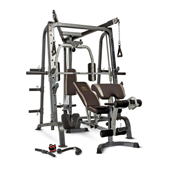
Page 22: Exploded Diagram
EXPLODED DIAGRAM... -
Page 23: Smith Machine Parts List
PARTS LIST KEY NO. DESCRIPTION Base Frame Cross Brace Front Vertical Beam Left Vertical Frame Right Vertical Frame Rear Vertical Beam Weight Glide Post Weight Glide Base Rear Upper Frame 10 Left Butterfly 11 Right Butterfly 12 Butterfly Base 13 Butterfly Pulley Bracket 14 Sliding Weight Post 15 Front Top Beam 16 Foot Plate... -
Page 24: Multi-Purpose Bench Hardware Pack
MULTI-PURPOSE BENCH HARDWARE PACK... -
Page 25: Multi-Purpose Bench Assembly Instructions
MULTI-PURPOSE BENCH ASSEMBLY INSTRUCTION Tools Required Assembling the Machine: Two Adjustable Wrenches and Allen Wrenches. NOTE: It is strongly recommended this machine be assembled by two or more people to avoid possible injury. STEP 1 (See Diagram 1) A.) Attach the Main Frame (#1) to the Front & Rear Stabilizers (#2 & 3). Secure each end with two M10 x ¾”... - Page 26 STEP 2 (See Diagram 2) A.) Attach four Bushings (#27) to a Seat Support Frame (#6). B.) Attach a Backrest Support (#7) to the rear of the Seat Support Frame (#6). Align the holes and secure them with one M10 x 1 ¾” Allen Bolt (#37) and procedure to install the other side.
- Page 27 STEP 3 (See Diagram 3) A.) Place the Backrest Board (#14) onto the Backrest Supports (#7). Secure it with four M8 x 2” Allen Bolts (#40) and B.) Place the Seat Pad (#13) onto the Seat Support Frames (#6). Secure it with four M8 x 2”...
- Page 28 STEP 4 (See Diagram 4) A.) Attach the Leg Developer (#5) to the open bracket on the Main Frame (#1). Secure it with an Axle (#17), two M10 x ¾” Allen Bolts (#36), and two B.) Insert one Foam Tube (#10) halfway through the hole on the Main Frame. Insert two Foam Tubes halfway through the holes on the Leg Developer (#5).
- Page 29 STEP 5 (See Diagram 5) A.) Attach the Arm Curl Pad (#15) to the Arm Curl Stand (#4). Secure it with two M8 x 5/8” Allen Bolts (#41) and two 5/8” Washers (#43). Insert the Arm Curl Stand into the front opening on the Main Frame (#1).
-
Page 31: Multi-Purpose Bench Parts List
MULTI-PURPOSE BENCH PARTS LIST KEY NO. DESCRIPTION Main Frame Front Stabilizer Rear Stabilizer Arm Curl Stand Leg Developer Seat Support Frame Backrest Support Sliding Block Incline Adjustment Bar Foam Tube Arm Curl Handle Manual Seat Pad Backrest Board Arm Curl Pad Curl Bar Handle Grip Axle Ø... -
Page 32: Weight Resistance Chart
MD-9010 WEIGHT RESISTANCE CHART Station Low Pulley Lat Pull Butterfly (both arms) Left Cross-Over Right Cross-Over *Numbers are approximate. Actual resistance may vary. Ratio Example 200% 10 lb. plate creates 20 lb. resistance 100% 10 lb. plate creates 5 lb. resistance 100% 10 lb. -
Page 33: Warranty
IMPEX. IMPEX is not responsible or liable for indirect, special or consequential damages arising out of or in connection with the use or performance of the product or other damages with respect to any economic loss, loss of property, loss of revenues or profits, loss of enjoyments or use, costs of removal, installation or other consequential damages or whatsoever natures.