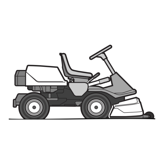
Jonsered FR 2113 MA 4X4 Operator's Manual
Ride-on mower
Hide thumbs
Also See for FR 2113 MA 4X4:
- Operator's manual (32 pages) ,
- Workshop manual (68 pages) ,
- Operator's manual (32 pages)

Related Manuals for Jonsered FR 2113 MA 4X4


Summary of Contents for Jonsered FR 2113 MA 4X4
- Page 1 Oper ator ′ s manual Please read the oper ator’s manual carefully and make sure you understand the instructions before using the machine. FR 2113MA 4X4 FR 2116MA 4X4...
-
Page 2: Table Of Contents
CONTENTS Contents Checking the engine’s cooling air intake ...... Checking and adjustment of the cutting unit’s ground CONTENTS pressure ............... Contents ..............Checking the cutting unit’s parallelism ......INTR ODUCTION Adjusting the parallelism of the cutting unit ....Dear Customer , ............Service position for the cutting unit ...... -
Page 3: Intr Oduction
Dear Customer , Thank y ou for choosing a Jonsered Frontrider. Jonsered Frontriders are built to a unique design with a front-mounted cutting unit and a patented rear-wheel steering system. FrontRiders are designed for maximum efficiency even in small or confined areas. The closely grouped controls and pedal-operated hydrostatic transmission also contribute to the performance of this machine. -
Page 4: Good Service
INTR ODUCTION Good ser vice Jonsereds products are sold all o ver the world and only through servicing dealers. This is to ensure that you, the customer, get the best support and service. For example, before this machine was delivered it was inspected and adjusted by your dealer. See the certificate in the Service Journal in this manual. -
Page 5: Ser Vice Journal
Ser vice journal Pre-deliver y service 1 Top up battery with acid and charge for four hours. 2 Fit steering wheel, seat and any optional equipment. 3 Check and adjust tyre pressure (60 Kpa, 0.6 bar). 4 Adjust cutting unit: Adjust lift springs (effective weight of cutting unit should be 12-15kg / 26.5-33 lb). -
Page 6: Key To Symbols
KEY T O SYMBOLS Symbols Ignition These symbols are on the machine and in the instr uctions. Hydrostatic free wheel WARNING! Careless or incorrect use can result in serious or fatal injury to the operator or others. Clutch in Please read the oper ator’s manual carefully and make sure you understand the instructions before using the machine. - Page 7 KEY T O SYMBOLS Starting instructions Check the engine’s oil level Check the hydrostat’s oil level Lift up the cutting unit Apply and loc k the parking brake. If the engine is cold, use the chok e Release the par king brake before driving Switch off the engine and tak e off the ignition cable before repairs or maintenance –...
-
Page 8: Safety Instructions
SAFETY INSTRUCTIONS Safety instructions • Look out for the ejector and do not direct it towards anyone. These instructions are for your safety. Read them carefully. • Stop the engine and prevent it from starting before you clean the cutting unit. Insure your Rider •... -
Page 9: Driving On Slopes
SAFETY INSTRUCTIONS Driving on slopes • Never allow children or other persons not trained in the use of the machine to use or service it. Local laws may regulate the age of the user. Driving on slopes is one of the operations where the risk of the driver losing control of the machine or of it overturning is the greatest;... -
Page 10: Children
SAFETY INSTRUCTIONS • Do not try to stabilize the machine by putting your foot on • Never fill the fuel tank indoors. the ground. • When cleaning the chassis, the machine may never be driven near verges or ditches. • Follow the manufacturer’s recommendations regarding wheel weights or counterbalance weights to increase machine stability. -
Page 11: Transport
SAFETY INSTRUCTIONS • Take care with battery maintenance. Explosive gases • Reduce the risk of fire by removing grass, leaves and form in the battery. Never perform maintenance on the other debris that may have fastened on the machine. battery while smoking or in the vicinity of open flames or Allow the machine to cool before putting it in storage. -
Page 12: What Is What
WHAT IS WHAT? Location of the controls 1 Throttle control/choke control 8 Lock button for parking brake 2 Ignition lock 9 Seat adjustment. 3 Cutting height adjustment lever 10 Lever to disengage the driving front axle 4 Lifting lever for the cutting unit 11 Fuel cap 5 Speed limiter for reversing 12 Cover lock... -
Page 13: Presentation
PRESENTATION Presentation Parking brake Congratulations on your choice of an excellent quality product The parking brake is applied as follows: that will give you great pleasure for many years. Two models equipped with four-wheel drive and engines from Briggs & Stratton are described in this operators manual. -
Page 14: Cutting Height Adjustment Lever
PRESENTATION Fuelling If the lock button is pressed in and the lever is moved forwards the unit will be lowered and the blades will automatically start to rotate (mowing position). The engine runs on unleaded petrol with a minimum octane rating of 85 (not mixed with oil). -
Page 15: Driving
Driving Before starting With a cold engine: 4 Move the throttle to position 3 (choke position). In this position the engine is fed with a richer mixture, which IMPORTANT INFORMATION The air intake grille in the means the engine is easier to start. engine cover behind the driver’s seat must not be blocked by, for example, clothing, leaves, grass or dirt. -
Page 16: Starting The Engine With A Weak Battery
Driving Starting the engine with a weak 2 Carefully press down one of the pedals until the required speed is obtained. Pedal (1) is used to drive forwards, and battery pedal (2) to drive backwards. WARNING! Lead-acid batteries produce explosive gases. Avoid sparks, open flames and smoking close to batteries. -
Page 17: Stop The Engine
Driving • The mowing results are best with a high engine speed Pull back the throttle and turn the ignition key to the (fast rotating blades) and low driving speed (slow moving ”STOP” position. machine). If the grass is not too high and thick, the driving speed can be increased without noticeably depreciating the mowing result. -
Page 18: Maintenance
Maintenance Maintenance schedule The following is a list of the maintenance which should be conducted on the machine. For those points not described in this manual, visit an authorised service workshop. Daily maintenance At least Maintenance Maintenance before starting once a year interval in hours 100 200 Cleaning... -
Page 19: Cleaning
Maintenance Cleaning Front cover Release the clip on the front hood and lift off the fender. Clean the machine directly after use. It is much easier to wash off grass cuttings before they dry. Oily dirt can be removed using a cold degreasing agent. Spray on a thin layer. -
Page 20: Checking And Adjusting The Steering Wires
Maintenance Temperature variations and vibrations can mean that the 3 If necessary, the wires can be adjusted by tightening the tightening torque for the screws drops. The screws should be adjuster nuts on each side of the steering collar. Do not checked when servicing to guarantee the correct torque. -
Page 21: Adjusting The Throttle Wire
Maintenance Adjusting the throttle wire 3 Pull off the filter from the hose ends. 4 Press the new filter into the ends of the hoses. If The throttle cable may need to be adjusted, if the engine does necessary apply liquid detergent to the ends of the filter to not respond as it should when accelerating, if it produces facilitate connection. -
Page 22: Checking The Fuel Pump's Air Filter
Maintenance 6 Insert a new precleaner and air filter cartridge in the fan WARNING! Procedures on contact with acid housing. 7 Align the tabs on the cover with the slits in the housing and replace the air filter cover. External: Rinse well with plenty of water. Internal: Drink large quantities of water or milk. -
Page 23: Check The Safety System
Maintenance Check the safety system The machine is equipped with a safety system that prevents starting or driving under the following conditions. The engine should only be possible to start when the cutting unit is in its raised position and the gear shift lever or hydrostat pedals are in the neutral position. -
Page 24: Main Fuse
Maintenance Main fuse Open the engine cover. Check that the cooling intake is free from leaves, grass and The main fuse is placed in a detachable holder under the dirt. battery case’s cover, in front of the battery. Type: Flat pin, 15 A. Check the air duct, located on the inside of the engine cover, Do not use any other type of fuse when replacing. -
Page 25: Checking The Cutting Unit's Parallelism
Maintenance Checking the cutting unit’s Service position for the cutting unit parallelism The cutting head can be placed in the service position to provide easy access for cleaning, repairs and servicing. In the Check the cutting unit’s parallelism as follows: service position the cutting unit is raised and locked in the vertical position. -
Page 26: Restoring From Service Position
Maintenance 3 Pull the frame forwards and refit the pin. WARNING! Wear protective glasses when dismantling the cutting unit. The spring which tensions up the belt may break and cause personal injury. 5 Disengage the spring for the drive belt tensioning wheel. 4 Grasp the front edge of the cutting unit, pull out and raise into the service position. -
Page 27: Checking The Blades
Maintenance Checking the blades Removing the Mulching plug, C94 To achieve the best mowing results it is important that the To change a Combi unit from the Mulching function to a blades are undamaged and well-sharpened. cutting unit with rear ejection, remove the Mulching plug, which is located under the unit, attached with a knob. -
Page 28: Lubrication
Lubrication Checking the engine’s oil level. 2 Remove the dipstick. Remove the drain plug from the engine’s left side. Check the oil level in the engine when the Rider stands horizontal with the engine switched off. Open the engine cover. Loosen the dipstick, pull it up and wipe it off. -
Page 29: Lubricating The Belt Adjuster
Lubrication Lubricating the front wheel bearings Work on the system entails particular demands on cleanliness and the system must be vented before the machine is used. The front cover and wing covers must be removed on Rider with rear ejection, so that the tubular loop can be lifted to remove the wheel. -
Page 30: Troubleshooting Schedule
Troubleshooting schedule Problem Procedure Engine does not start There is no fuel in the fuel tank Spark plug defective Faulty spark plug connections or interchanged cables Dirt in the carburettor or fuel line Dirt in the carburettor or fuel line Starter motor does not turn over the engine Battery flat Bad contact between the cable and battery... -
Page 31: Storage
Storage Winter storage Guard At the end of the season, or if the machine is going to stand There is a cover to protect your machine during storage or idle for more than 30 days, it should immediately be made transport. -
Page 32: Technical Data
TECHNICAL DATA FR 2113 MA 4X4 FR 2116 MA 4X4 Dimensions Length without cutting unit, mm/ft 2010/6,58 2010/6,58 Length with cutting unit, mm/ft 2220/7,29 2220/7,29 Width without cutting unit, mm/ft 880/2,89 880/2,89 Width with cutting unit, mm/ft 1140/3.74 Height, mm/ft 1090/3.58... -
Page 33: Ec-Declar Ation Of Conformity
EC-declaration of conformity (Applies to Europe only) Husqvarna AB, SE-561 82 Huskvarna, Sweden, tel.: +46-36-146500, hereby declares that Jonsered FR 2113 MA 4X4 and FR 2116 MA 4X4 from 2006’s serial numbers and onwards (the year is clearly stated in plain text on the rating plate with subsequent serial number), complies with the requirements of the COUNCIL’S DIRECTIVE:... - Page 34 ´®z+R@r¶6x¨ ´®z+R@r¶6x¨...
- Page 36 1150328-26 ´®z+R@r¶6x¨ ´®z+R@r¶6x¨ 2006-12-12...