
Related Manuals for Mira Vie


Summary of Contents for Mira Vie
- Page 1 MIRA VIE ELECTRIC SHOWER Installation and User Guide These instructions are to be left with the user...
-
Page 2: Table Of Contents
Important Safety Information ..............5 Warning! ....................5 Caution! ....................7 Pack Contents ..................8 Mira Vie 8.5 kW, 9.5 kW or 10.8 kW Electric Shower ......8 Specifications ..................9 Dimensions ................... 9 Wiring Diagram ................... 10 Plumbing .................... 11 Electrical ..................... -
Page 3: Introduction
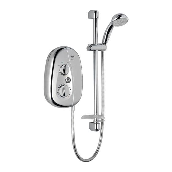
A 9.5 kW 240 V AC (8.7 kW 230 V AC) heater with push-button Start/Stop. Available in a white/chrome or chrome finish. Mira Vie 10.8 A 10.8 kW 240 V AC (9.9 kW 230 V AC) heater with push-button Start/Stop. Available in a white/chrome, satin/chrome or chrome finish. -
Page 4: Guarantee
GUARANTEE For domestic installations, Mira Showers guarantee the Mira Vie 8.5, 9.5 kW and 10.8kW against any defect in materials or workmanship for a period of two years from the date of purchase (shower fittings for one year). For non-domestic installations, Mira Showers guarantee the Mira Vie 8.5, 9.5 kW and 10.8kW against any defect in materials or workmanship for a period of... -
Page 5: Important Safety Information
18. DO NOT fit any form of outlet flow control as the outlet acts as a vent for the tank body. Only Mira Showers recommended outlet fittings should be used. 19. If water leaks from the pressure relief valve, maintenance will be required before the appliance can be safely used. - Page 6 22. DO NOT operate this appliance if water leaks from this appliance. 23. Only a competent person should remove the front cover. We recommend any maintenance work is carried out by a Mira Service Engineer or qualified tradesperson. 24. Mains connections are exposed when the cover is removed. Isolate the electrical and water supply before removing the cover.
-
Page 7: Caution
Caution! Read all of these instructions and retain this guide for later use. Make sure that this guide is left with the user Pass on this guide in the event of change of ownership of the installation site. Follow all warnings, cautions and instructions contained in this guide, and on or inside the shower. -
Page 8: Pack Contents
PACK CONTENTS Tick the appropriate boxes to familiarise yourself with the part names and to confirm that the parts are included. Mira Vie 8.5 kW, 9.5 kW or 10.8 kW Electric Shower 3 x Wall Plugs 3 x Fixing Screws ... -
Page 9: Specifications
SPECIFICATIONS Dimensions All dimensions are nominal and in millimetres. -
Page 10: Wiring Diagram
Wiring Diagram... -
Page 11: Plumbing
The 10.8 kW requires a 45 Amp fuse. The terminal block will not accept cable larger than 10 mm The Mira Vie is suitable for installation in Zone 1 and is rated IP X4. Standards and Approvals This Mira Vie shower complies with all of the relevant directives for CE marking. -
Page 12: Installation Requirements
INSTALLATION REQUIREMENTS Plumbing The Mira Vie 8.5 kW and 9.5 kW electric showers are designed to operate with a minimum maintained inlet pressure of 70 kPa (0.7 bar) up to a maximum static inlet pressure of 1000 kPa (10 bar). - Page 13 13. Supply pipework MUST be flushed to clear debris before connecting the appliance. 14. The appliance is fitted with a 1/2” BSP male outlet thread, to accept an Mira Vie shower hose. 15. When installed in very hard water areas (above 200 ppm temporary hardness) your installer may advise the installation of a water treatment device, to reduce the effects of limescale formation.
-
Page 14: Electrical
Electrical In a domestic installation, the rating of the electricity supply company fuse and the consumer unit must be adequate for the additional demand. This is a high-power appliance, and it is essential to contact your electricity supply company to ensure that the supply is adequate for the appliance. Voltage drop due to local heavy demand will reduce the performance of the shower. -
Page 15: Installation
INSTALLATION Warning! Isolate the electrical and water supplies before commencing installation. The electricity must be turned off at the mains and the appropriate circuit fuse removed, if applicable. DO NOT turn-on the electrical supply until the plumbing has been completed. Determine a position for the shower, at least 200 mm from the ceiling. - Page 16 10. The case has thinned sections that Thinned Section can be removed to allow entry of the supply pipe and electrical cables. Remove the top thinned section of the case for a falling supply, or remove the bottom thinned section of the service tunnel for a rising supply.
- Page 17 18. Bring the electrical cables into the case. 19. Strip a short section of the electrical cables. 20. Fit an earth sleeve to the earth wire. 21. Loosen the screws in the terminal block and insert the bare wires into the clamps: L (Live) = Brown Wire ) (Earth) = Green Sleeved Wire...
-
Page 18: Commissioning
COMMISSIONING Caution! If you are unsure how electric showers work, please read the Operation section before continuing. Turn the shower OFF by pressing the power button. Make sure that the button is in the OFF position. Turn the temperature knob fully anticlockwise to cold and the power knob to low. -
Page 19: Operation
OPERATION Advice to Users Note! Read the Important Safety Information section first. DO NOT operate this appliance if water leaks from this appliance. Warning! Do not switch on if there is a possibility that the water in the appliance is frozen. Warning! The shower head must be de-scaled regularly. -
Page 20: Operating Instructions
Operating Instructions To turn the shower on Switch on the electrical supply at the double pole switch. The light around the power button will turn on. Turn the shower ON by pressing the power button. Turn the power knob to High. Wait 15-20 seconds for warm water to reach the handset. -
Page 21: Fault Diagnosis
FAULT DIAGNOSIS The troubleshooting information tabled below gives you details on probable causes and remedies should difficulties be encountered whilst the shower is in operation. Warning! There are no user serviceable components beneath the cover of the appliance. Only a competent tradesperson should remove the FRONT cover! Malfunction Cause Remedy... - Page 22 Malfunction Cause Remedy No hot water Other water outlets Make sure the other water outlets, from shower, with are being used during such as the washing machine or the knobs in any showering, causing the dishwasher, are not in use during position.
- Page 23 Malfunction Cause Remedy Turning the The flow regulator is faulty. Replace the flow regulator. temperature knob does not affect the The handset sprayplate is Remove and clean the handset water temperature. blocked. sprayplate. Refer to the shower fittings User Guide. If the fault persists, contact Customer Services.
- Page 24 Malfunction Cause Remedy Water leaks from the The pressure relief valve Resolve the blocked outlet, and bottom of the case in the tank has been replace the tank assembly. near the outlet, and triggered, (the shower has there is no flow from a pressure relief valve the handset.
-
Page 25: Maintenance
MAINTENANCE Any maintenance must be carried out by a qualified tradesperson, following the instructions provided. Before replacing any parts, make sure that the underlying cause of the malfunction has been resolved. Warning! There are no user-serviceable components beneath the cover of the appliance. -
Page 26: Relief Valve Assembly - Resetting
Relief Valve Assembly - Resetting Warning! Isolate the electrical and water supplies before removing the cover. Mains electricity connections are exposed when the cover is removed. Remove the three screws that hold Screws the cover and remove the cover. Note! The rubber ball is ejected to reduce any damage if the outlet is blocked or the appliance is frozen. -
Page 27: Spare Parts
SPARE PARTS Spare Parts List 406.27 Filter 439.74 Spare Neon Assembly 439.75 Inlet Connector Assembly 439.76 Clamp Bracket Pack (components identified ‘A’) 439.78 Flow Regulator Assembly, 9.5/10.8 kW 439.80 Switch Assembly, Push Button 9.5/10.8 kW 439.88 Seal Pack (components identified ‘B’) 439.89 Screw Pack (components identified ‘C’) 439.90... -
Page 28: Spare Parts Diagram
Spare Parts Diagram 439.80 406.27 439.74 439.75 1539.349 1539.379 439.78 439.90 439.92 439.93 439.94 439.97 439.98 439.99 1539.400 1539.406 1539.440 Important Note! Push-fit connectors must be assembled back to back onto the terminals of the micro-switches. A minimum air gap of 4 mm must be maintained between the connectors after assembly. -
Page 29: Accessories
ACCESSORIES Genuine Mira accessories can be purchased direct from Customers Services (our contact details can be found on the back cover of this guide) or from approved stockists or merchants. Everclear Showerhead Shower Seat White - 2.1616.030 White - 2.1536.128 Chrome - 2.1616.031... -
Page 30: Notes
NOTES... - Page 31 NOTES...
-
Page 32: Customer Service
fi lters) or where no fault has been found with guarantee period and beyond. You have the assurance of a the product. fully trained Mira Technician, genuine Mira spare parts and Water or electrical supply, waste and isolation issues. a 12 month guarantee on any chargeable work done.