
Related Manuals for Axminster 200387


Summary of Contents for Axminster 200387
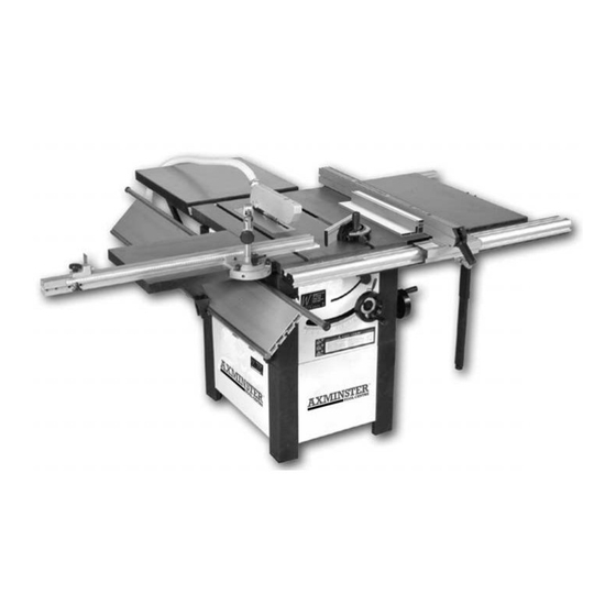
- Page 1 10"&12" Sliding Table Saws Axminster Reference No’s: A X M I N S T E R AW10BSB2 & AW12BSB2 W H I T E w w w. a x m i n s t e r. c o . u k...
-
Page 2: Table Of Contents
Index of Contents... Page No. Index of Contents........................02 Declaration of Conformity………….………..……..………….......... 03 What’s in the Box Part 1-2-3..……..…………............04-05-06 General Instructions for 230v Machines............06-07-08 Specifications….………..……..…………..............08-09 Initial Assembly Instructions..................09 Assembling the Main Saw Bench................. 10-11 Assembling the Rear Extension Table..............12 Mounting the First Side Extension Leaf..............13 Mounting the Slide Rail Assembly............... -
Page 3: Declaration Of Conformity
Index of Contents... A X M I N S T E R W H I T E Page No. Maintenance....................... 33 Changing the Saw Blade................... 34 Specific Instructions/Precautions for the Saw Bench..........35 Parts List/Breakdown for the 10/12" Saw Table........36-37-38-39-40 Notes........................41-47 Parts List/Breakdown for the 10/12"... -
Page 4: What's In The Box Part 1-2-3
Height Adjusting Blocks (for slide rail mounting brackets) 2 No. Rear Extension Table Brackets. For assembling main Dust Extraction Hose and Top Guard Hose 1 No. Packet containing :- 2 No. 125mm Jubilee Clips 2 No. 40mm Jubilee Clips www.axminster.co.uk... - Page 5 What’s in the Box Part 2... A X M I N S T E R W H I T E For assembling Lower Base Legs and Panels, rear extension table Pkt containing: 12 No. M8 x 20mm Hexhead Bolts, Nuts and 2 x Washers (Fixing panels) 4 No.
-
Page 6: General Instructions For 230V Machines
Only use a 13 Amp plug, and make sure the cable clamp is tightened securely. Fuse as required. If extension leads are to be used, carry out the same safety checks on them, and ensure that they are correctly rated to safely supply the current that is required for your machine. www.axminster.co.uk... - Page 7 General Instructions for 230v Machines... A X M I N S T E R W H I T E Work Place/Environment The machine is not designed for sub-aqua operation, do not use when or where it is liable to get wet. If the machine is to be used outside and it starts to rain (unusual though this would be in U.K.), stop work and move it inside.
-
Page 8: Specifications
YOUR COMMON SENSE. REMEMBER, YOU ARE ULTIMATELY REPONSIBLE FOR YOUR OWN SAFETY THIS MACHINE IS DESIGNED TO CUT TIMBER AND TIMBER DERIVATIVE PRODUCTS. DO NOT use for any other materials. Specification... Axminster No. AW10BSB2 AW12BSB2 200387 600890 Motor Single phase 230V, 50 Hz: 2.2kW... -
Page 9: Initial Assembly Instructions
Specification... A X M I N S T E R W H I T E Maximum throat before the Saw with slide rails fully forward: 1220mm Supported length behind the saw blade: 900mm Table height: 845mm Tilt Angle: 0-45 degrees Minimum Kerf: Maximum Depth of Cut (at 90˚... -
Page 10: Assembling The Main Saw Bench
(as seen in fig 4) until it is resting on the pallet with its legs on the floor. Lift the machine upright. (See fig 5) M8x20mm bolts, nuts and double washers Upper leg Lower leg Fig 1 Fig 2a Fig 2 www.axminster.co.uk... - Page 11 Assembling the Main Saw Bench... A X M I N S T E R W H I T E Rear panel with the dust Dust extraction moulding extraction moulding fitted Fig 3 Extraction hose Front panel Fit the remaining Fig 4 panels to the legs Blind face Fig 5...
-
Page 12: Assembling The Rear Extension Table
Leave all bolts finger tight at this time. Side panels removed Fig 7 Fig 6 Inside face of the leg Table bracket M8 caphead bolts Fig 8 Fig 9 and washers Table fixing holes Mount the table onto the brackets www.axminster.co.uk... -
Page 13: Mounting The First Side Extension Leaf
Mounting the First Side Extension Leaf... A X M I N S T E R W H I T E THE EXTENSION LEAF IS HEAVY YOU MAY REQUIRE A SECOND PERSON TO HELP LIFT IT IN PLACE Select one of the extension leaves, (either one, they are identical) locate 4 No. M8 hexhead bolts and washers. -
Page 14: Mounting The Sliding Table
Unlock the clamping bolt of the support leg and allow the inner section to slide through until the foot is resting on the floor. Do not put the leg under tension at this time. 'Nip' up the clamp bolt. www.axminster.co.uk... -
Page 15: Mounting The Front Guide Rail And Rear Clamping Rail For The Rip Fence
Mounting the Second Side Extension Leaf... A X M I N S T E R W H I T E Second Fig 12 Support leg extension leaf M8x20mm hexhead bolt Turn the leaf upside down on a work surface (or the saw table?) and attach the support leg to the outside edge, using the 20mm bolts and fastening through the two middle holes. -
Page 16: Setting The Machine Tables
(See figs 15 & 16) The final phase is only a 'jacking' exercise and should not affect the previous settings. Make sure all the fixing bolts are generally finger tight. www.axminster.co.uk... -
Page 17: Setting The Sliding Table
Setting the Sliding Table... A X M I N S T E R W H I T E Fig 15 Fig 16 Set the sliding table so that the front edge is inline with the front edge of the saw table. Place a long straight edge (a bit more than twice the width of the sliding table) along the front edges of the two tables. -
Page 18: Mounting The Micro-Adjustor To The Rip Fence Mounting Bracket
Pinch up the fixing bolts. www.axminster.co.uk... -
Page 19: Fitting The Hand Wheels
Mounting the Sliding Table Fence Assembly... A X M I N S T E R W H I T E Introduce the Clamping Handle through its clamping washer and the arc slot into the tapped hole in the sliding table. Pinch up the Clamping handle. Mount the distance stop by introducing the dog into the wide channel in the top of the fence extrusion. -
Page 20: Fitting The Switch Shroud
Push the jubilee clips over the ends of the hose, push the hose onto the spigots of the guard and the main dust extraction moulding and tighten the clips to hold it in place. See figs 21 & 22 www.axminster.co.uk... -
Page 21: Fitting The Small Mitre Fence
Attaching the Saw Hood Guard and the Extraction Hose... A X M I N S T E R W H I T E There is no requirement to remove the guard. The profile of the riving knife precludes the use of the saw for slotting or grooving, and the maximum depth of cut can be achieved with the guard in place. -
Page 22: Setting And Checking The Machine
Check the pointer is still correct. If the preset positioning is wrong, set the fence with a square/mitre gauge, set the pointer accurately against the scale, and clamp the fence in position without recourse to the presets. Remove the small mitre fence from the table and stow carefully aside. www.axminster.co.uk... - Page 23 Setting and Checking the Machine... A X M I N S T E R W H I T E Check the belt tension (see fig 24) the belt should be tight, but not unduly so. Remove all tools and stow away. Check that the machine tables are clear. Lower the saw to leave about 25mm protruding, set the saw upright.
-
Page 24: Identification & Description Of The Saw Table
Tilt angle A small star knob situated above the rise and fall control handle that lock locks the tilt mechanism to prevent any movement that could be caused (See fig A) by vibration during the saw operation. www.axminster.co.uk... -
Page 25: Illustration & Parts Description Of The Saw
Illustration & Parts Description of the Saw... A X M I N S T E R W H I T E Table insert Riving knife Extension Saw Table table 'T' slot Extension table Upper chassis Extension table support leg Fig A Lower chassis Tilt control Tilt angle lock... - Page 26 Channels in the extrusion capture the nuts of the fixing bolts, this allows the fence and the micro-adjustor to be fastened to the bracket. There is a magnifying sight glass with an index line recessed into the bracket. www.axminster.co.uk...
- Page 27 Illustration & Parts Description of the Saw... A X M I N S T E R W H I T E Rip fence and Blade guard mounting bracket Rip fence Rear fence clamping rail Rip/guide fence mounting rail Fig B Tilt angle scale Emergency...
- Page 28 Identification & Description of the Saw Table.. A X M I N S T E R W H I T E Mounting Two lamina plates shaped to the extruded section of the rip fence bracket mounting bracket and secured by self tapping screws. They blank off capping plates the voids at the ends of the bracket.
- Page 29 Illustration & Parts Description of the Saw... A X M I N S T E R W H I T E Slide table assembly Mitre fence Fig C Rip fence micro-adjuster Typ. 2 Height adjuster Typ. 2 Slide rail bracket adjuster Side rail bracket Securung bolt 0800 371822...
- Page 30 The secondary extrusion can be locked in position by a star handled bolt, which clamps the two extrusions together. Note: Only the END o the extention rail is in the same plane as the face of the fence. www.axminster.co.uk...
- Page 31 Illustration & Parts Description of the Saw... A X M I N S T E R Preset stops W H I T E Table fence Main tool post Mitre angle rear mounting quadrant Sliding table Siding table fence Length stop Fig D Extention lock Slide rail assembly...
- Page 32 Drive belt See Maintenance Section. tensioning Illustration & Parts Description of the Saw... support bracket Fig E Dust extraction Rear extraction duct table www.axminster.co.uk...
-
Page 33: Maintenance
Maintenance... A X M I N S T E R W H I T E Keep the saw as clean and free from saw dust build up as is practical. Periodically, remove the saw gullet and blow out brush out clean out the saw box and the extraction hosing. -
Page 34: Changing The Saw Blade
ON-OFF) to ensure everything is O.K. If everything is satisfactory, continue to use the machine. Check the old blade for sharpness, missing teeth, resin buildup, etc., clean if necessary and send for refurbishment/resharpening if required. If the blade is not to be re-sharpened, clean and pack away in its stowage case. www.axminster.co.uk... - Page 35 Specific Instructions/Precautions for the Saw Bench... A X M I N S T E R W H I T E Make sure the saw blade is the correct type for the job in hand. DO NOT force the saw, if the saw begins to 'stall' you are 'forcing the cut' or over working the saw.
- Page 36 Parts List/Breakdown for the 10/12" Saw Table... A X M I N S T E R W H I T E DIAGRAM A www.axminster.co.uk...
- Page 37 Parts List/Breakdown for the 10/12" Saw Table... A X M I N S T E R W H I T E 0800 371822 FREEPHONE...
- Page 38 Parts List/Breakdown for the 10/12" Saw Table... A X M I N S T E R W H I T E www.axminster.co.uk...
- Page 39 Parts List/Breakdown for the 10/12" Saw Table... A X M I N S T E R W H I T E DIAGRAM B 0800 371822 FREEPHONE...
- Page 40 Parts List/Breakdown for the 10/12" Saw Table... A X M I N S T E R W H I T E DIAGRAM C www.axminster.co.uk...
- Page 41 Notes... A X M I N S T E R W H I T E 0800 371822 FREEPHONE...
- Page 42 Parts List/Breakdown for the 10/12" Saw Table... A X M I N S T E R W H I T E www.axminster.co.uk...
- Page 43 Parts List/Breakdown for the 10/12" Saw Table... A X M I N S T E R W H I T E DIAGRAM D 0800 371822 FREEPHONE...
- Page 44 Parts List/Breakdown for the 10/12" Saw Table... A X M I N S T E R W H I T E DIAGRAM E www.axminster.co.uk...
- Page 45 Parts List/Breakdown for the 10/12" Saw Table... A X M I N S T E R W H I T E DIAGRAM F 0800 371822 FREEPHONE...
- Page 46 Parts List/Breakdown for the 10/12" Saw Table... A X M I N S T E R W H I T E DIAGRAM G www.axminster.co.uk...
- Page 47 Notes... A X M I N S T E R W H I T E 0800 371822 FREEPHONE...
- Page 48 Axminster Reference No’s: AW10BSB2 & AW12BSB2 Axminster Devon EX13 5PH UK A X M I N S T E R W H I T E FREEPHONE 0800 371822 www.axminster.co.uk...