Table of Contents
Advertisement
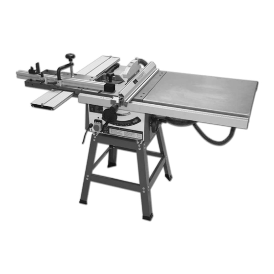
TS-200 200mm
Table Saw
950650
Basic Saw
700059
Leg Stand
700060
Sliding Table Kit
Kit
Order No's
718641:
TS-200 Table Saw
950650:
TS-200 Basic Saw
700059:
TS-200 Leg Stand
700058:
TS-200 R/H Extension Table Kit
700060:
TS-200 Sliding Table Kit
Axminster Reference No:TS-200
w w w. a x m i n s t e r. c o . u k
718641
Table Saw
700058
R/H Extension Table
W
A X M I N S T E R
W H I T E
Advertisement
Table of Contents

Related Manuals for Axminster TS-200


Summary of Contents for Axminster TS-200
- Page 1 TS-200 R/H Extension Table Kit 700060: TS-200 Sliding Table Kit A X M I N S T E R W H I T E Axminster Reference No:TS-200 w w w. a x m i n s t e r. c o . u k...
-
Page 2: Table Of Contents
Index of Contents... Page No. Index of Contents.......................01 Declaration of Conformity………….……..…………...........01 Parts Index………….………..……..…..........02-03-04-05-06 General Instructions for 230V Machines............06-07-08 Specific Instructions/Precautions for the Saw Table...........08-09 Specifications….………..……..…………..............10 Assembly Instructions….………..…....…10-11-12-13-14-15-16-17-18-19 Illustration & Parts Description ................20-21 Setup & Adjustments....................22-23 Operating Instructions………..……..…………..........24-25 Changing the Saw Blade..................25-26 Maintenance...................... -
Page 3: Parts Index
Parts Index... A X M I N S T E R W H I T E Model Number: HM-TS200 Kit Order No’s. Quantity Description 950650,718641 1 off Basic Table Saw (with Saw Blade & Riving Knife fitted) 700060 2 off Sliding Carriage Supporting Arms 950650,718641 1 off... - Page 4 Parts Index... A X M I N S T E R W H I T E Kit Order No’s. 32 off M8 x 12 Coach Bolts with Nuts 4 off M8 x 11 Bolts with Large Washer & Nut 700059,718641 1 off Saw Guard with M6 x 25 Coach Bolt &...
- Page 5 Parts Index... A X M I N S T E R W H I T E...
- Page 6 Parts Index... A X M I N S T E R W H I T E 950650: Fence Supporting Arm www.axminster.co.uk...
-
Page 7: General Instructions For 230V Machines
Parts Index... A X M I N S T E R W H I T E General Instructions for 230V Machines... Good Working Practices/Safety The following suggestions will enable you to observe good working practices, keep yourself and fellow workers safe and maintain your tools and equipment in good working order. - Page 8 General Instructions for 230V Machines... A X M I N S T E R W H I T E Fuse as required. If extension leads are to be used, carry out the same safety checks on them, and ensure that they are correctly rated to safely supply the current that is required for your machine.
-
Page 9: Specific Instructions/Precautions For The Saw Table
General Instructions for 230V Machines... A X M I N S T E R W H I T E DO NOT use this machine within the designated safety areas of flammable liquid stores or in areas where there may be volatile gases. There are very expensive, very specialised machines for working in these areas, THIS IS NOT ONE OF THEM. - Page 10 The assistant does not push, pull, guide etc., unless specifically asked or instructed to do so by the sawyer. Specification... Axminster No. TS-200 Order No: 950650...
-
Page 11: Assembly Instructions
Assembly Instructions... A X M I N S T E R W H I T E Initial Assembly Please take some time to read the section entitled “Identification and Parts Description” to identify the various parts of your machine so that you are familiar with the terminology we will use to enable you to set up and operate your table saw safely and correctly. - Page 12 Assembly Instructions... A X M I N S T E R W H I T E Attaching the Saw Guard Steel Mesh (Kits: 950650, 718641) Locate the Saw Guard Steel Mesh (B3), turn the Saw Bench (A) upside down and remove the four phillips screws &...
- Page 13 Assembly Instructions... A X M I N S T E R W H I T E Assembling the Sliding Carriage Table (Kits: 700060, 718641) Place an M6 x 16mm hex bolt in each of the four clearance holes on both support arms (B), and loosely put an M6 nut and washer on the bottom of each.
- Page 14 Assembly Instructions... A X M I N S T E R W H I T E Angle Fence Assembly (Kits: 700060, 718641) Put to hand the work clamp block (O), and slide it onto the T-slot on the angle fence (W). Locate the connecting block (O) and slide it onto the angle fence as before.
- Page 15 Assembly Instructions... A X M I N S T E R W H I T E Angle Fence Assembly (Kits: 700060, 718641) Fig 20 Fig 21 To set the angle fence (W) to angles between 45˚ and 90˚ loosen the three lift and shift handles on the connecting &...
- Page 16 Assembly Instructions... A X M I N S T E R W H I T E Fig 26 Fig 27 Tilt operating wheel handle Operating Wheel Handles Assembly (Kits: 950650, 718641) Locate the two operating wheel handles (F) and, using the supplied 3mm allen key (J), secure one to the tilt mechanism shaft to the front of the saw by undoing the grub screw on the operating wheel handle (F) and sliding it onto the shaft, making sure the grub screw is in line with machined slot (a), in the shaft.
- Page 17 Assembly Instructions... A X M I N S T E R W H I T E Locate the two extension table support arms (X). Remove the plastic cover to the left hand side of the support arm with the scale. (See fig 32). Slot the extension table support arm (X) onto the M6 nuts so that nut sits in the T -slot.
- Page 18 Assembly Instructions... A X M I N S T E R W H I T E Extension Table Assembly Part 2 (Kits: 700058, 718641) Remove the plastic covers from the ends of the two extension table support arms (X), (see fig 38).
- Page 19 Assembly Instructions... A X M I N S T E R W H I T E Fence Assembly (Kits: 700058, 718641) Lower the fence assemby so the clamp assembly (N) slots over the extention table support arm (X), clamp the fence assembly in position by turning the knob clockwise. (See figs 44 & 45).
- Page 20 Assembly Instructions... A X M I N S T E R W H I T E Dust Extraction Assembly (Kits: 718641, 700058) (718641 Only) Remove the nuts, bolts & washers from the 30mm hose support bracket (H), line up the pre-drilled holes to the underside of the rear extention support arm (X) & secure using the nuts,bolts &...
-
Page 21: Illustration & Parts Description
Illustration & Parts Description... A X M I N S T E R W H I T E NVR On/Off switch shroud A Saw Bench M Flip Over Stop B1 Push Stick O Work Clamp/Connecting Blocks C Work Clamp Assembly P Leg ‘A’... - Page 22 Illustration & Parts Description... A X M I N S T E R W H I T E X Extension Table Support Arms Z Fence Y Extension Table Z1 Hoses 50mm & 30mm www.axminster.co.uk...
-
Page 23: Setup & Adjustments
Setup & Adjustments... A X M I N S T E R W H I T E Adjusting the Riving Knife Raise the saw blade to its highest point and remove the saw blade guard. Remove the four hex screws and place carefully aside, remove the table insert. Using the spanner provided loosen the riving knife and adjust until the tip of the riving knife is 3mm away from the saw blade &... - Page 24 Release the locking handle (A), the saw can be angled up to a maximum of 45˚ by turning the hand wheel (B). (See fig 63). NOTE: If the blade is at maximum height, it will need to be lowered by 10mm when the pivot angle is 30˚ or more. www.axminster.co.uk...
-
Page 25: Operating Instructions
Operating Instructions... A X M I N S T E R W H I T E NOTE: Before using your table saw, go round and make sure everything is secure, fastened down, that all tool, are cleared away from the work area. CHECK the blade for sharpness, missing teeth, resin buildup, etc., clean if necessary. -
Page 26: Changing The Saw Blade
Operating Instructions... A X M I N S T E R W H I T E The Mitre Fence The mitre fence can be mounted on either side of the saw blade in the two ‘T’ slots, pre machined into the saw table. (See fig 26). The mitre fence can be angled from 90˚ to 45˚ degrees . -
Page 27: Maintenance
Assembly Instructions... A X M I N S T E R W H I T E Sawplate washer Fig 70 Fig 69 Remove the saw blade Tighten up the saw bolt, check the riving knife is aligned with the saw blade, and correctly positioned. -
Page 28: Parts Breakdown For Ts-200 Table Saw
Parts Breakdown for TS-200 Table Saw... A X M I N S T E R W H I T E www.axminster.co.uk... - Page 29 Parts Breakdown for TS-200 Table Saw... A X M I N S T E R W H I T E 0800 371822 FREEPHONE...
-
Page 30: Parts List For Ts-200 Table Saw
Parts List for TS-200 Table Saw... A X M I N S T E R W H I T E www.axminster.co.uk... -
Page 31: Parts List & Breakdown For The Sliding Carriage
Parts LIst & Breakdown for the Sliding Carriage... A X M I N S T E R W H I T E 0800 371822 FREEPHONE... - Page 32 Axminster Reference No:TS-200 A X M I N S T E R W H I T E Axminster Devon EX13 5PH UK FREEPHONE 0800 371822 www.axminster.co.uk...