
Related Manuals for Axminster AC1950B


Summary of Contents for Axminster AC1950B
- Page 1 AC1950B Code 105093 AC2305B Code 105094 AC2606B Code 105095 Original Instructions Bandsaws 10,12,14 inch AC1950B AC2305B AC2606B AT&M: 04/02/2019 BOOK REF: 105742...
- Page 2 Parts Breakdown/List 32-33-34-35-36-37-38 Wiring Diagram Cert No: MJ3420, MJ3425, EU Declaration of Conformity MJ343C, MJ343B This machine complies with the following directives: Axminster Tools & Machinery Ltd Axminster Devon EX13 5PH UK 2006/42/EC axminster.co.uk EN 1807-1:2013 declares that the machinery described:- EN 60204-1:2006+A1+AC 06/42/EC - Annex I/05.2006...
- Page 3 What’s Included Model Number AC1950B Model Number AC2305B Model Number AC2606B Quantity Item Part Quantity Item Part Quantity Item Part 105093 Bandsaw 105094 Bandsaw 105095 Bandsaw Blade 1,950mm long, Blade 2,305mm long, Blade 2,606mm long, mounted on saw but not...
- Page 4 What’s Included Optional Accessory...
-
Page 5: General Instructions For 230V Machines
What’s Included HAVING UNPACKED YOUR SAW (SEE BELOW) AND ITS ACCESSORIES PLEASE DISPOSE OF ANY UNWANTED PACKAGING PROPERLY. THE CARDBOARD PACKAGING IS BIODEGRADABLE. General Instructions for 230V Machines The following will enable you to observe good working • Carry out a final check e.g. check the cutting tool practices, keep yourself and fellow workers safe and maintain is securely tightened in the machine and the correct your tools and equipment in good working order. - Page 6 Specification Code 105093 Code 105094 Model AC1950B Model AC2305B Rating Craft Rating Craft Power (Output) 550 W Power (Output) 750 W Blade Speed 660 & 840 m/min Blade Speed 360 & 720 m/min Blade Length 1,950mm Blade Length 2,305mm Blade Width Min/Max...
- Page 7 Assembly Step 3 Step 5 Step 4 Step 6 Mounting the Bandsaw to the Stand WHEN MOUNTING THE UNIT, WE STRONGLY ADVISE YOU GET THE ASSISTANCE OF ANOTHER PERSON AS THE BANDSAW IS HEAVY. Lift the saw on to the stand, secure using four long bolts, nuts and washers (10).
- Page 8 Assembly Fig 04-05 Mounting the Saw Table Locate the blade tensioning knob (6) and insert it down over the control shaft ,on top of the bandsaw housing, see fig 01. 1) The saw table can be fitted without removing the blade. However, if you would feel more comfortable not having to manoeuvre the table around the blade, remove the blade by opening the top and bottom covers, release the tension on...
- Page 9 Assembly Fig 08-09 Fence Assembly lower it onto the mounting plate, see fig 10. Line up the holes in the tilt quadrant with the ones in the mounting plate, replace 1) Locate the guide fence rail (3) and guide fence assembly (4). the bolts/washers and tighten.
- Page 10 Assembly 2) Locate the guide fence assembly (4), lowering the fence Fig 22-23 down over the fence rail (3) and press down the locking lever to secure the fence in position, see fig 17-18. Fig 17-18 Retaining clip 2) Place a retaining clip over the end of the hose (7), slide the hose over the port (5) and tighten the clip.
-
Page 11: Illustration And Parts Description
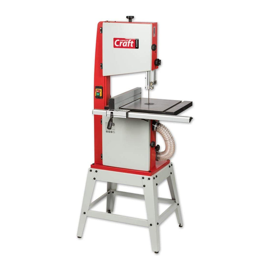
Upper blade guide & guard ‘T’ slot for mitre fence NVR On/Off switch Cast iron table Stabilising bolt Fence locking lever Fence guide rail Saw frame Flexible extraction hose Lower door locking knob Lower door wheel Floor stand Rubber foot AC1950B Bandsaw... - Page 12 Illustration and Parts Description Blade tensioning knob Blade observation window Upper door locking knob Upper door wheel Upper blade guide adjusting knob & clamp Upper blade guide & guard Fence ‘T’ slot for mitre fence NVR On/Off switch Cast iron table Stabilising bolt Fence locking lever Fence guide rail...
- Page 13 Illustration and Parts Description Micro switch Upper wheel tracking and tensioning assembly Upper saw wheel Micro switch Bandsaw blade Lower saw wheel Drive belt Drive pulley...
- Page 14 Illustration and Parts Description AC2305B Bandsaw AC2606B Bandsaw Blade tensioning scale Blade guide adjusting knob (A) Tracking control knob (C) Blade guide clamp (B) Tracking butterfly lock (D)
- Page 15 Illustration and Parts Description AC1950B Bandsaw Blade tensioning scale Push stick Table levelling stop bolt Motor assembly Dust extraction outlet Blade guide adjusting knob (E) Tilt quadrant (G), Tilt scale (H) Blade guide clamp F) Tilt scale pointer and adjusting screw (I), Lift and shift handle (J)
- Page 16 Upper blade guide assembly for AC2305B and AC2606B Bandsaw Rear thrust bearing and clamping grub screw (A) Fore and aft clamping grub screw (B) Upper blade guide assembly for AC1950B Bandsaw Rear thrust bearing and clamping grub screw (C) Fore and aft clamping grub screw (D)
-
Page 17: Setting Up The Saw
Setting Up the Saw Fig 28-29 DISCONNECT THE SAW FROM THE MAINS SUPPLY! Tensioning and tracking the blade Make sure both top and bottom blade guides and thrust bearing are well clear of the blade, see fig 26 Fig 26 1) Open the front covers fully, giving good access to the top compartment of the saw and good visibility into the bottom compartment, see page 13. - Page 18 31-32. Note this applies only for model numbers AC2305B and AC2606B bandsaws. To tension the drive belt on model AC1950B, loosen the motors clamping Hex bolt and press the assembly down.
- Page 19 Loosen the bolts holding the tilt quadrant, using a Hex key adjust the four grub screws in the quadrant. For model AC1950B, adjust the grub screws beneath the mounting plate, Pointer see fig 39-40. Make small adjustments, lower the table and postion the square as before.
- Page 20 Setting Up the Saw 3) To make sure the fence is perfectly square to the blade we Fig 43 recommend using our unique bandsaw blade aligning tool, called the Bandsaw Buddy, see our website for details. The Bandsaw Buddy allows you to check the alignment of the bandsaw blade to the face of the fence.
- Page 21 Setting Up the Saw Fig 54-55 DISCONNECT THE SAW FROM THE MAINS SUPPLY! 1mm behind the blade Setting the Blade Guides 1) Loosen the blade guide clamp and lower the upper blade guide to approximately 1 1/2”(38mm) above the table, secure in place.
- Page 22 AC2305B, AC2606B, see fig 60. Loosen the bolt to the under side of the bottom wheel housing for model AC1950B, see fig 61. Note you may need to remove the lower wheel brush to gain access to the bolt, see fig 62.
-
Page 23: Operating Instructions
‘working’ for 30-60 mins. The blade will ‘stretch’ slightly when new. Note: For the AC1950B we recommend a vacuum style extractor, 13) Do not release the tension on the saw blade when work is such as the AC50E, code 105251. For the AC2305B and AC2606B complete. -
Page 24: Changing The Saw Blade
Changing the Saw Blade DISCONNECT THE SAW FROM THE MAINS SUPPLY! 1) Put the table back to the level position if it has been tilted. Open up all blade guides so that they are clear of the blade and open the wheel doors. Set the upper blade guide assembly approximately midway in the throat so the top of the blade guide is level with the centre of the top drive wheel, see fig 67. - Page 25 Changing the Saw Blade Drive belt tensioner & tracking control assembly 5) If you are fitting a new blade, it will have been supplied to you “folded” , bound together in this configuration with tape or tie wrap. WARNING! BE VERY CAUTIOUS WHEN YOU “UNFOLD”...
-
Page 26: Changing The Blade Speed
80-81. Note: to release the belt tension on the AC1950B bandsaw, loosen the motor Hex bolt, see fig 82 and pull the Pulley grooves motor up. - Page 27 Maintenance DISCONNECT THE SAW FROM THE MAINS SUPPLY! Daily • Keep the machine clean. • Check the saw blade for missing teeth and cracks, see fig 85. • Spray Axcaliber Dry Lubricant on the bare metal surfaces. Fig 85 Check for missing teeth and cracks in the blade Weekly...
- Page 28 50mm. When cutting metals reduce About Axcaliber Bandsaw Blades the speed as much as possible especially when cutting ferrous Axcaliber bandsaw blades are manufactured at Axminster using metals or cast iron. advanced CNC machining, high precision digital measuring equipment and specialised heat treatment facilities.
- Page 29 Bandsaw Blade Information Premium Bandsaw Blades •Premium blades made from M42 with 8% cobalt. • Long life with high resistance to heat, abrasion and vibration. • Variable pitch teeth for wider ranging applications. • Also used for cutting metal on horizontal bandsaws. Blades are available in three variable pitch forms 4-6tpi, 6-10tpi and 10-14tpi.
- Page 30 Below is the list of top recommended accessories and machinery regular servicing (preventative maintenance) is up-sell items for the bandsaw. Please visit our website at axminster.co.uk essential to get the best from your saw. Axminster • This is the most common question that you will get from bandsaw users.
- Page 31 INTRODUCTION KEY FEATURES • Bandsaw Buddy is a unique bandsaw blade aligning tool. • Designed and made in Axminster Bandsaw Buddy allows you to check the alignment of the • Unique bandsaw blade aligning tool bandsaw blade to the face of the fence. Most other checks only require the use of a combination or engineer’s square.
- Page 32 Parts Breakdown/List Model AC1950B...
- Page 33 Parts Breakdown/List Description Adjusting knob,upper guide Guide bracket Wing nut Motor Motor pulley Lower wheel shaft Adjusting rack,upper guide Upper wheel shaft Protection cover,lower guide Upper wheel shaft seat Saw frame Micro switch ass’y Sliding axle bracket Upper door Upper wheel sliding axle Lower door Spring Hinge...
- Page 34 Parts Breakdown/List Model AC1950B Description Table pin Guide piece Right cap,front rail Square neck bolt M6X25 Left cap,fence carrier Hex.bolt M8X45 Right cap,fence carrier Worktable Screw guide Mounting base,worktable Pointer Rotating base,worktable Locking shaft,fence carrier Extension table Circle ring Table insert...
- Page 35 Parts Breakdown/List Model AC2305B, AC2606B Continues over...
- Page 36 Parts Breakdown/List Description Lower guide guard Guide bracket Saw frame Motor Micro switch ass’y Lower wheel shaft Upper door Upper wheel shaft Lower door Upper wheel shaft seat Hinge Sliding axle bracket Drive belt Upper wheel sliding axle Touching plate,micro switch Spring Washer 4 Strip washer...
- Page 37 Parts Breakdown/List Model AC2305B, AC2606B Description Left cap,fence carrier Guide piece Right cap,fence carrier Square neck bolt M6X25 Screw guide Hex.bolt M8X45 Pointer Worktable Locking shaft,fence carrier Mounting base,worktable Circle ring Rotating base,worktable Lock plate Table insert Cross recessed countersunk screw M4X8 Fence carrier Cross recessed pan head tapping screw ST4X16 Rip fence...
- Page 38 Parts Breakdown/List Model AC1950B, AC2305B, AC2606B Description Hex.nut M8 Upper long bracket Hex.nut M6 Stand leg Hex.bolt M6X35 Upper short bracket Hex.bolt M8X30 Lower short bracket Gasket nut Lower long bracket Rubber mat Hex.socket pan head screw M6X16 Washer 8 Washer 8 Hex.nut M8...
-
Page 39: Wiring Diagram
Wiring Diagram Model AC1950B Model AC2305B, AC2606B... - Page 40 The Axminster guarantee is available on Craft, Trade, Engineer, Air Tools & CNC Technology Series machines Buy with confidence from Axminster! So sure are we of the quality, we cover all parts and labour free of charge for three years! For more information visit axminster.co.uk/3years...