Table of Contents
Advertisement
Quick Links
asseMbly and Operating instructiOns
Visit our website at: http://www.harborfreight.com
read this material before using this product.
Failure to do so can result in serious injury.
saVe this Manual.
Copyright
2002 by Harbor Freight Tools
©
contained herein may be reproduced in any shape or form without the express written consent of Harbor
Freight Tools. Diagrams within this manual may not be drawn proportionally. Due to continuing improve-
ments, actual product may differ slightly from the product described herein. Tools required for assembly
and service may not be included.
For technical questions or replacement parts, please call 1-800-444-3353.
Revised Manual 10f
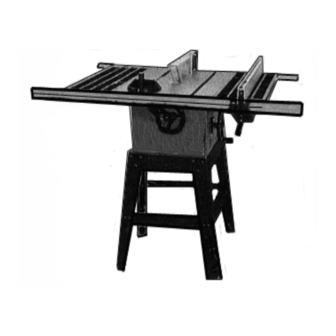
10" table saw
Model
. All rights reserved. No portion of this manual or any artwork
®
46813
Advertisement
Table of Contents

Related Manuals for Central Machinery 46813


Summary of Contents for Central Machinery 46813
- Page 1 Failure to do so can result in serious injury. saVe this Manual. Copyright 2002 by Harbor Freight Tools . All rights reserved. No portion of this manual or any artwork © ® contained herein may be reproduced in any shape or form without the express written consent of Harbor Freight Tools.
-
Page 2: Specifications Table
Keep children away FrOM wOrK area. Do not allow children to handle this product. stOre idle eQuipMent. When not in use, tools and equipment should be stored in a dry location to inhibit rust. Always lock up tools and equipment and keep out of reach of children. SKU 46813 PAGE 2... - Page 3 ANSI approved safety impact eyeglasses, hearing protectors, dust masks and respirators are available from Harbor Freight Tools. dress saFely. Non-skid footwear or safety shoes should be used when work- ing with this product.
-
Page 4: Specific Product Warnings And Precautions
FOrce the eQuipMent. This Table Saw will do the work better and safer at the speed and capacity for which it was designed. SKU 46813 PAGE 4... - Page 5 Saw Blade rated at least 3,400 rpM to prevent possible injury. reduce the risK OF KicKbacK. Kickback is caused when the Saw Blade (part #14-I) becomes pinched, miss-aligned, or twisted during the cutting process, resulting in personal injury and/or damage to the tool. SKU 46813 PAGE 5...
- Page 6 (California Health & Safety Code 25249.5, et seq.) warning: People with pacemakers should consult with their physician(s) before using this product. Operation of equipment in close proximity to a heart pacemaker could cause interference or failure of the pacemaker. SKU 46813 PAGE 6...
-
Page 7: Product Overview
BEVEL KNOB (#30C) SCALE RIP FENCE (#10G) HANDLE HEIGHT (#37C) FRONT RAIL HANDLE (#7H) (#5G) END BRACE (#6B) SIDE BRACE (#7B) LEG (#4B) LONG LEG SHORT LEG BRACE (#10B) BRACE (#9B) LEVELING FOOT (#1B) Figure b SKU 46813 PAGE 7... - Page 8 Figure c SKU 46813 PAGE 8...
-
Page 9: Assembly Instructions
(part #4B), using one Carriage Bolt (part #5B), one Washer (part #3B), and one Hex Nut (part #2B) for each Long Leg Brace. Repeat the assembly procedure for the remaining one Long Leg Brace and two Legs. (see Figure b, and assy. diagram b.) SKU 46813 PAGE 9... - Page 10 Braces to the Base, using four Hex Head Bolts (part #8B), eight Washers (part #3B), and four Hex Nuts (part #2B). (see Figure d, and assy. diagram b.) nOte: Leave the 10” Saw Table upside down for the next assembly procedure. SKU 46813 PAGE 10...
- Page 11 1/2”. (see Figure F, and assy. diagram h.) Loosely attach a Washer (part #12H) and Hex Nut (part #13H) to each Square Head Bolt (part #10H). (see Figure F, and assy. diagram h.) SKU 46813 PAGE 11...
- Page 12 EXTENSION HEX HEAD BOLT TABLE (#5H) (#11H) HEX HUT (#13H) WASHER (#12H) Figure e 10” TABLE SAW EXTENSION TABLE (#5H) (#13H) EXTENSION WASHER TABLE (#5H) (#12H) SQUARE HEAD BOLT (#10H) Figure F SKU 46813 PAGE 12...
- Page 13 Insert five Square Head Bolts (part #10H) through the mounting holes in the rear edges of the 10” Table Saw and Extension Tables (part #5H). Allow the bolt heads to extend out about 1/2”. (see Figures i, J, and assy. diagram h.) SKU 46813 PAGE 13...
- Page 14 Figure i nOte: The back side of the Rear Rail (part #3H) has one slot. Slide the slot of the Rear Rail over the Square Head Bolts (part #10H). (see Figures i, J, and assy. diagram h.) SKU 46813 PAGE 14...
- Page 15 To attach the Miter Gauge Assembly (parts #1A through 12A), simply slide the Miter Gauge Rod (part #10A) into the right or left slot (nearest the Saw Blade opening, on the Saw Table (part #17H). (see Figure b, and assy. diagrams a, and h.) SKU 46813 PAGE 15...
- Page 16 Slide the Switch Plate (part #3E) to a convenient position. Then, secure the entire Switch Assembly (parts #1E through #12E) to the Front Rail (part #7H) by tightening the two Semi-Circle Head Screws (part #2E). (see Figures b, g, and assy. diagram e.) SKU 46813 PAGE 16...
- Page 17 (see Figure M, and assy. diagrams i, and g.) Align the four mounting holes in the Motor Bracket (part #7F) with the four mounting holes in the Motor Mounting Plate (part #50-I). (see Figure n, and assy. diagrams F, and i.) SKU 46813 PAGE 17...
- Page 18 Screws yet. (see assy. diagram i.) To Attach The Belt Guard: Open the hinged Belt Guard (parts #1F, #4F) and insert its round opening over the Motor Pulley (part #5F). (see Figures n, O, and assy. diagram F.) SKU 46813 PAGE 18...
- Page 19 Slip the V-Belt (part #40-I) onto the Pulley (41-I) inside the Base (part #1G). (see Figure p, and assy. diagram i.) PULLEY (#41-I) OUTER BELT GUARD (#1F) V-BELT (#40-I) MOTOR BASE PULLEY (#1G) (#5F) INNER BELT GUARD (#4F) Figure p SKU 46813 PAGE 19...
- Page 20 Throat Plate (part #15H)). Then, remove the Throat Plate to expose the 10” Saw Blade opening. (see Figures Q, r, and assy. diagram h.) SAW TABLE (#17H) THROAT PLATE (#15H) FLAT HEAD SCREW (#16H) Figure Q SKU 46813 PAGE 20 reV 04/03...
- Page 21 Table and against the back sides of the 10” Saw Blade teeth. Then while holding the scrap wood firmly in place, wrench tighten the Blade Nut onto the Arbor Shaft to secure the 10” Saw Blade. (See Figures R, S, and Assy. Diagram I.) SKU 46813 PAGE 21...
- Page 22 Saw Table (part #17H), replace the Throat Plate (part #15H) and tighten the Flat Head Screw (part #16H) back in place. (See Figure Q, and Assy. Diagram H.) SOCKET HEAD SCREW(#5D BLADE GUARD (#10D) WASHER (#4D) BLADE GUARD BRACKET (#3-I) FIGURE T SKU 46813 PAGE 22...
-
Page 23: Operating Instructions
The 10” Table Saw is capable of making bevel cuts from 90 degrees to 45 degrees. The 10” Table Saw also features a Bevel Scale (part #10G) on the front side of the unit. (See Figure B, and Assy. Diagram G.) SKU 46813 PAGE 23... -
Page 24: Inspection, Maintenance, And Cleaning
(See Figure B, and Assy. Diagram I.) INSPECTION, MAINTENANCE, AND CLEANING Caution: Always disconnect the 10” Table Saw from its electrical power supply source before performing any inspection, maintenance, or cleaning. SKU 46813 PAGE 24... - Page 25 You may use a mild detergent. Do not introduce water into the electric motor through the motor vents. Once clean, lubricate all moving parts with a light weight oil. When storing, keep the 10” Table Saw covered with a cloth cover. SKU 46813 PAGE 25...
- Page 26 UNDERTAKEN BY CERTIFIED AND LICENSED TECHNICIANS, AND NOT BY THE BUYER. THE BUY- ER ASSUMES ALL RISK AND LIABILITY ARISING OUT OF HIS OR HER REPAIRS TO THE ORIGINAL PRODUCT OR REPLACEMENT PARTS THERETO, OR ARISING OUT OF HIS OR HER INSTALLATION OF REPLACEMENT PARTS THERETO. SKU 46813 PAGE 26...
-
Page 27: Parts List
PARTS LIST SKU 46813 PAGE 27... - Page 28 PARTS LIST 22-H Rack REV 10f SKU 46813 PAGE 28...
- Page 29 PARTS LIST NOTE: Some parts are listed and shown for illustration purposes only, and are not available individually as replacement parts. SKU 46813 PAGE 29...
-
Page 30: Assembly Diagram B
ASSEMBLY DIAGRAM B NOTE: Some parts are listed and shown for illustration purposes only, and are not available individually as replacement parts. SKU 46813 PAGE 30... - Page 31 ASSEMBLY DIAGRAM C NOTE: Some parts are listed and shown for illustration purposes only, and are not available individually as replacement parts. SKU 46813 PAGE 31...
- Page 32 ASSEMBLY DIAGRAM D NOTE: Some parts are listed and shown for illustration purposes only, and are not available individually as replacement parts. SKU 46813 PAGE 32...
- Page 33 ASSEMBLY DIAGRAM E NOTE: Some parts are listed and shown for illustration purposes only, and are not available individually as replacement parts. SKU 46813 PAGE 33...
- Page 34 ASSEMBLY DIAGRAM F NOTE: Some parts are listed and shown for illustration purposes only, and are not available individually as replacement parts. SKU 46813 PAGE 34...
- Page 35 ASSEMBLY DIAGRAM G NOTE: Some parts are listed and shown for illustration purposes only, and are not available individually as replacement parts. SKU 46813 PAGE 35...
- Page 36 ASSEMBLY DIAGRAM H NOTE: Some parts are listed and shown for illustration purposes only, and are not available individually as replacement parts. REV 10f SKU 46813 PAGE 36...
- Page 37 ASSEMBLY DIAGRAM I NOTE: Some parts are listed and shown for illustration purposes only, and are not available individually as replacement parts. SKU 46813 PAGE 37...
-
Page 38: Limited 1 Year / 90 Day Warranty
LIMITED 1 YEAR / 90 DAY WARRANTY Harbor Freight Tools Co. makes every effort to assure that its products meet high quality and durability standards, and warrants to the original purchaser that for a period of ninety days from date of purchase that the engine/motor, the belts (if so equipped), and the blades (if so equipped) are free of defects in materials and workmanship.