Table of Contents
Advertisement
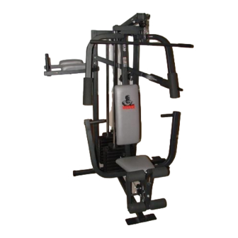
Model No. WESY87300
Serial No.
Write the serial number in the space
above for reference.
Serial Number Decal (Under Seat)
QUESTIONS?
As a manufacturer, we are com-
mitted to providing complete
customer satisfaction. If you
have questions, or if there are
missing or damaged parts, we
will guarantee you complete
satisfaction through our
Customer Service Department.
Please CALL:
0345-089009
Or WRITE:
ICON Fitness Lifestyle Ltd.
Greenwich House
223 North Street
Sheepscar
Leeds LS7 2AA
West Yorkshire
CLASS H C Fitness Product
CAUTION
Read all precautions and instruc-
tions in this manual before using
this equipment. Save this manual
for future reference.
USER'S MANUAL
Visit our website at
www.weiderfitness.com
new products, prizes,
fitness tips, and much more!
Advertisement
Table of Contents

Related Manuals for Weider 8530


Summary of Contents for Weider 8530
- Page 1 Model No. WESY87300 USER'S MANUAL Serial No. Write the serial number in the space above for reference. Serial Number Decal (Under Seat) QUESTIONS? As a manufacturer, we are com- mitted to providing complete customer satisfaction. If you have questions, or if there are missing or damaged parts, we will guarantee you complete satisfaction through our...
- Page 2 TABLE OF CONTENTS IMPORTANT PRECAUTIONS .............2 BEFORE YOU BEGIN .
-
Page 3: Before You Begin
WEIDER 8530 (see the front ® WEIDER ® 8530 will help you to achieve the specific cover of this manual). results you want. Before reading further, please review the drawing For your benefit, read this manual carefully before... - Page 4 • Place all parts of the WEIDER 8530 in a cleared • Tighten all parts as you assemble them, unless area and remove the packing materials; do not instructed to do otherwise.
- Page 5 2. Insert two 5/16” x 2 1/2” Carriage Bolts (1) up through the Base (4). Slide the Front Upright (42) onto the 5/16” x 2 1/2” Carriage Bolts (1) in the Base (4). Hand-tighten a 5/16” Nylon Locknut (3) onto each Carriage Bolt.
- Page 6 5. Press a Weight Tube Bumper (64) into the end of a Weight Tube (63). Insert the Weight Holes Tube into the front stack of Weights (25). Be sure that the pins on the Weight Tube are sitting in the pin grooves in the top Weight.
- Page 7 7. Attach the upper ends of the Long Weight Guides (62) to the Top Frame (55) with a 5/16” x 6” Bolt (60), two 1/2” x 3/4” Spacers (61), and a 5/16’ Nylon Locknut (3). Be sure that the Pulley Bracket (20) is in front of the right Long Weight Guide (62) as shown.
- Page 8 11. Lubricate both axles on the Top Frame (55). Bracket Slide the Right Arm (48) onto the right axle. Be careful not to confuse the Right Arm with the Left Arm (47); note the position of the “V” Pulley (50) to identify the Right Arm.
- Page 9 During steps 13 to 25, refer to the CABLE DIA- GRAM on page 19 of this manual. Identify the three cables by their lengths, and note the posi- tions of the cable traps. IMPORTANT: Do not over- tighten the bolts and nuts securing the pulleys. The pulleys must turn freely.
- Page 10 17. Route the Medium Cable (58) around the 3 1/2” Pulley (15) attached to the bracket on the Top Frame (55). Tighten the 3/8” x 2” Bolt (12) and the 3/8” Nylon Locknut (21). (Note: This Pulley is Bracket pre-assembled. It has been shown disassem- bled for easy part identification.) Be sure that the Cable is in the groove of the Pulley and that the Cable and Pulley move smoothly.
- Page 11 21. Attach the Medium Cable (58) to a Small “U”- Bracket (71) with a 1/4” Nylon Locknut (2) and a 1/4” Flat Washer (10). Do not tighten the 1/4” Nylon Locknut. It should be threaded onto the Cable only a couple of turns.
- Page 12 24. Wrap the Long Cable (72) around a 3 1/2” Pulley (15). Attach the Pulley and two Pulley Wide Covers (96) to the Squat Arm (84) with the Tabs 3/8” x 2 1/4” Bolt (94) and a 3/8” Nylon Jam Nut (92).
- Page 13 26. Attach the Backrest (41) to the Front Upright (42) with two 1/4” x 2 1/2” Screws (43) and two 1/4” Flat Washers (10). 43 10 27. Press a 1 1/2” Inner Cap (32) into the Seat Frame (36). Insert a 1/4” x 2” Carriage Bolt (38) through the centre hole in the Seat Plate (37).
- Page 14 30. Press two 3/4” Round Inner Caps (34) into each 13 1/2” Pad Tube (28). Insert the 13 1/2” Pad Tube (28) into the Seat Frame (36). Slide a 6” Pad (30) onto each end of the Pad Tube. Insert the other 13 1/2” Pad Tube (28) into the Leg Lever (29).
-
Page 15: How To Use The Home Gym System
34. Apply the 8530 decal to the Front Upright (42) in the indicated location. The top of the decal should be 6” from the top of the Front Upright. Decal HOW TO USE THE HOME GYM SYSTEM The instructions below describe how each part of the home gym system can be adjusted. IMPORTANT: When attaching the lat bar or nylon strap, make sure that the attachments are in the correct starting position for the exercise to be performed. - Page 16 ATTACHING THE LAT BAR OR NYLON STRAP TO THE LOW PULLEY STATION Attach the Lat Bar (54) to the Short Cable (23) with a Cable Clip (53). For some exercises, the Chain (52) should be attached between the Lat Bar and the Short Cable with two Cable Clips.
- Page 17 WEIGHT RESISTANCE CHART This chart shows the approximate weight resistance at each station. “Top” refers to the 6,5 lbs. top weight. The other numbers refer to the 12,5 lbs. weight plates. The butterfly arm resistance listed is the resistance for each butterfly arm.
- Page 18 TROUBLE-SHOOTING AND MAINTENANCE Inspect and tighten all parts each time you use the home gym system. Replace any worn parts immediately. The home gym system can be cleaned using a damp cloth and mild non-abrasive detergent. Do not use solvents. TIGHTENING THE CABLES Woven cable, the type of cable used on the home gym system, can stretch slightly when it is first used.
-
Page 19: Cable Diagram
CABLE DIAGRAM The cable diagram below shows the proper routing of the Long Cable (72), the Medium Cable (58), and the Short Cable (23). Use the diagram to be sure that the three cables and cable traps have been assembled cor- rectly. -
Page 20: Ordering Replacement Parts
4. The KEY NUMBER and DESCRIPTION of the part(s) (see the PART LIST and EXPLODED DRAWING attached at the centre of this manual.) Part No. 144512 R0600A WEIDER is a registered trademark of ICON Health & Fitness, Inc. © 2000 Printed in Canada... - Page 21 REMOVE THIS PART IDENTIFICATION CHART FROM THE MANUAL This chart is provided to help you identify the small parts used in assembly. Important: Some parts may have been pre-assembled for shipping purposes. If you cannot find a part in the parts bags, check to see if it has been pre-assembled.
- Page 22 1/4" Nylon Locknut (2) 1/4" x 2" Machine Screw (81) 5/16" Nylon Locknut (3) 5/16" x 2 1/2" Bolt (22) 3/8" Nylon Locknut (21) 3/8" x 2" Bolt (12) 3/8" Nylon Jam Nut (92) 5/16" x 2 1/4" Bolt (33) 1/4"...
- Page 23 1/4" x 3/4" Screw (18) 3/8" x 3 1/2" Bolt (16) 3/8" x 3 3/4" Bolt (88) 5/16" x 5" Bolt (68) Cable Clip (53) 1" Retainer (69) 1 1/8" x 2 1/2" Plastic Bushing (89) 1" x 7/8" Plastic Bushing (90) 3 1/2"...
- Page 24 5/16" x 2" Eyebolt (35) 1/2" x 17/32" Spacer (91) 5/8" x 5/8" Spacer (76) 3/4" Round Inner Cap (34) 1" Round Inner Cap (49) 1" Round Cover Cap (70) 1/2" x 3/4" Spacer (61) 5/8" x 9/16" Spacer (7) 1"...
- Page 25 REMOVE THIS PART LIST/EXPLODED DRAWING FROM THE MANUAL!
- Page 26 PART LIST—Model No. WESY87300 R0600A Key No. Qty. Description Key No. Qty. Description 5/16” x 2 1/2” Carriage Bolt 2” Outer Cap 1/4” Nylon Locknut Chain 5/16” Nylon Locknut Cable Clip Base Lat Bar Stabiliser Top Frame 1” Inner Cap Squat Arm Upright 5/8”...
- Page 27 EXPLODED DRAWING—Model No. WESY87300 R0600A...