Table of Contents
Advertisement
NOTE:
Please read all instructions
carefully before using this
product
Table of Contents
Safety Notice
Hardware Identifier
Assembly Instruction
Parts List
Warranty
Ordering Parts
Model
MD-9010G
Retain This
Manual for
Reference
120925
OWNER'S
MANUAL
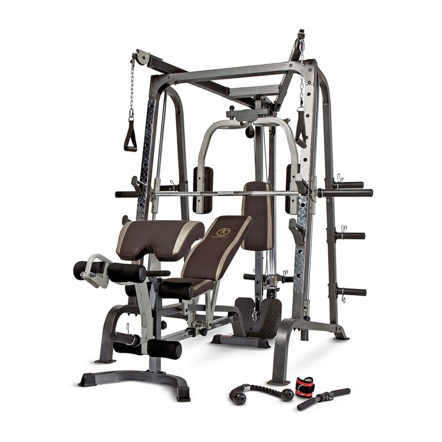
MARCY
SMITH MACHINE
2801 S. Towne Ave, Pomona, CA 91766
Tel: (800) 999-8899 Fax: (626) 961-9966
www.impex-fitness.com
info@impex-fitness.com
®
DIAMOND ELITE
MD-9010G
®
IMPEX
INC.
Advertisement
Table of Contents

Related Manuals for Impex MARCY DIAMOND ELITE MD-9010G


Summary of Contents for Impex MARCY DIAMOND ELITE MD-9010G
-
Page 1: Impex Inc
NOTE: Please read all instructions carefully before using this product ® MARCY DIAMOND ELITE Table of Contents Safety Notice SMITH MACHINE Hardware Identifier MD-9010G Assembly Instruction Parts List Warranty Ordering Parts Model MD-9010G Retain This Manual for Reference 120925 OWNER'S MANUAL ®... -
Page 2: Table Of Contents
BEFORE YOU BEGIN ® ® Thank you for selecting the MARCY DIAMOND ELITE MD-9010G by IMPEX INC. For your safety and benefit, read this manual carefully before using the machine. As a manufacturer, we are committed to provide you complete customer satisfaction. -
Page 3: Important Safety Notices
IMPORTANT SAFETY NOTICE PRECAUTIONS This exercise machine is built for optimum safety. However, certain precautions apply whenever you operate a piece of exercise equipment. Be sure to read the entire manual before you assemble or operate your machine. In particular, note the following safety precautions: 1. -
Page 4: Smith Machine Hardware Pack
The warning labels shown here have been placed on the Rear Base, Rear Stabilizer, and Upper Frame. If the labels are missing or illegible, please call customer service at 1-800-888-8899 for replacements. Apply the labels in the location shown. SMITH MACHINE HARDWARE PACK... - Page 6 SMITH MACHINE HARDWARE PACK...
-
Page 7: Smith Machine Assembly Instructions
SMITH MACHINE ASSEMBLY INSTRUCTION Tools Required Assembling the Machine: Two Adjustable Wrenches and Allen Wrenches. NOTE: It is strongly recommended two or more people assembling this machine to avoid possible injury. STEP 1 (See Diagram 1) A.) Connect the two Base Frames (#1) by a Cross Brace (#2) in the mid-span. Secure each end of The Cross Brace with two M10 x 3 ½”... - Page 8 STEP 2 (See Diagram 2) A.) Attach a Front Vertical Frame (#3) to the right Base Frame (#1). Secure it with two M10 x 3” Carriage Bolts (#76), one 5 1/8” x 2 ¾” Bracket (#34), two Ø ¾” Washers (#66), and two M10 Aircraft Nuts (#86).
- Page 9 DIAGRAM 2...
- Page 10 STEP 3 (See Diagram 3) A.) Attach the Rear Vertical Beam (#6) to the top of the Cross Brace (#2). Attach the Weight Glide Base (#8) to the Cross Brace from the Bottom. Align the holes. Secure them with two M10 x 3” Carriage Bolts (#76), Ø ¾” Washers (#66), and M10 Aircraft Nuts (#86). B.) Attach the Pulley Support Frame (#97) to the Rear Vertical Beam.
- Page 11 STEP 4 (See Diagram 4) A.) Attach the Weight Glide Post (#7) onto the Weight Glide Base (#8). Secure it with four M10 x 1” Carriage Bolts (#74), Ø ¾” Washers (#66) and M10 Aircraft Nuts (#86). B.) Slide the Sliding Weight Post (#14) onto the Chromed Post from the top. Place the Rear Upper Frame (#9) onto the Weight Glide Post (#7) and Rear Vertical Beam (#6).
- Page 12 STEP 5 (See Diagram 5) A. Place the Left Upper Frame (#94) onto the Front Top Beam (#15). Secure it with two M10 x 3 1/8” Carriage Bolts (#77), one 5 1/8” x 2 3/8” Bracket (#35), two Ø ¾” Washers (#66), and two M10 Aircraft Nuts (#86).
- Page 13 STEP 6 (See Diagram 6) A.) Securely tighten all Nuts and Bolts previously installed. B.) Attach the Butterfly Base (#12) to the front of Rear Vertical Beam (#6). Attach the Butterfly Pulley Bracket (#13) to the back of the Rear Vertical Beam. Align the holes. Secure them with two M10 x 2 ¾”...
-
Page 14: Cable Loop Diagram
CABLE LOOP DIAGRAM... - Page 15 STEP 7 (See Diagram 7 & Cable Loop Diagram) A.) Attach one end of 87” Butterfly Cable (#42) to the clip on Right Butterfly (#11). Draw the Cable to the right Swivel Pulley Bracket (#20). B.) Attach a Pulley (#57) to the Bracket. Secure it with one M10 x 1 ¾” Allen Bolt (#69), two Ø ¾” Washers (#66), and one M10 Aircraft Nut (#86).
- Page 16 STEP 8 (See Diagram 8 & Cable Loop Diagram) A.) Un-install the M10 x 1 1/8” Allen Bolt (#104) and M10 Aircraft Nut (#86) on the U-shaped Connector on one end of the 229” Cable (41). Remove the U-shaped Connector, Big Washer, and Ball Stopper from the Cable.
- Page 18 STEP 9 (See Diagram 9 & Cable Loop Diagram) A.) Attach one end of the 138” Sliding Weight Post Cable (#102) to the open bracket on the Sliding Weight Post (#14). Secure it with one M10 x 1” Allen Bolt (#68), two Ø ¾” Washers (#66), and one M10 Aircraft Nut (#86).
- Page 19 DIAGRAM 9...
- Page 20 STEP 10 (See Diagram 10) A.) Attach the 59” Lower Cable (#40) to a Pulley (#57). Attach the Pulley to the lower opening on the Rear Vertical Beam (#6). Secure it with the Foot Plate (#16), one M10 x 3 3/8” Allen Bolt (#73), two Ø...
- Page 21 STEP 11 (See Diagram 11) A.) NOTE: Help of another person is strongly recommended for this step. Place the Lifting Sleeve (#27) in between the two Safety Stop Frames (#26). Align the holes. Insert the Weight Bar (#28) into the Safety Stop Frame from one end and through the Lifting Sleeve (#27) to the other Safety Stop Frame on the opposite side.
-
Page 22: Exploded Diagram
EXPLODED DIAGRAM... -
Page 23: Smith Machine Parts List
PARTS LIST KEY NO. DESCRIPTION Q’ty Base Frame Sliding Sleeve Cross Brace Lock Ring Front Vertical Beam Pulley Left Vertical Frame Ø 1 ¾” Rubber Bumper Right Vertical Frame Ø 2 ½” Rubber Bumper Rear Vertical Beam Spring Clip Weight Glide Post C-clip Weight Glide Base Pulley Bushing... -
Page 24: Multi-Purpose Bench Hardware Pack
MULTI-PURPOSE BENCH HARDWARE PACK... -
Page 25: Multi-Purpose Bench Assembly Instructions
MULTI-PURPOSE BENCH ASSEMBLY INSTRUCTION Tools Required Assembling the Machine: Two Adjustable Wrenches and Allen Wrenches. NOTE: It is strongly recommended this machine be assembled by two or more people to avoid possible injury. STEP 1 (See Diagram 1) A.) Attach the Main Frame (#1) to the Front & Rear Stabilizers (#2 & 3). Secure each end with two M10 x ¾”... - Page 26 STEP 2 (See Diagram 2) A.) Attach four Bushings (#27) to a Seat Support Frame (#6). B.) Attach a Backrest Support (#7) to the rear of the Seat Support Frame (#6). Align the holes and secure them with one M10 x 1 ¾” Allen Bolt (#37) and ¾” Washer (#42). Repeat the same procedure to install the other side.
- Page 27 STEP 3 (See Diagram 3) A.) Place the Backrest Board (#14) onto the Backrest Supports (#7). Secure it with four M8 x 2” Allen Bolts (#40) and 5/8” Washers (#43). B.) Place the Seat Pad (#13) onto the Seat Support Frames (#6). Secure it with four M8 x 2”...
- Page 28 STEP 4 (See Diagram 4) A.) Attach the Leg Developer (#5) to the open bracket on the Main Frame (#1). Secure it with an Axle (#17), two M10 x ¾” Allen Bolts (#36), and two ¾” Washers (#42). B.) Insert one Foam Tube (#10) halfway through the hole on the Main Frame. Insert two Foam Tubes halfway through the holes on the Leg Developer (#5).
- Page 29 STEP 5 (See Diagram 5) A.) Attach the Arm Curl Pad (#15) to the Arm Curl Stand (#4). Secure it with two M8 x 5/8” Allen Bolts (#41) and two 5/8” Washers (#43). Insert the Arm Curl Stand into the front opening on the Main Frame (#1).
-
Page 31: Multi-Purpose Bench Parts List
MULTI-PURPOSE BENCH PARTS LIST KEY NO. DESCRIPTION Q’ty Main Frame Front Stabilizer Rear Stabilizer Arm Curl Stand Leg Developer Seat Support Frame Backrest Support Sliding Block Incline Adjustment Bar Foam Tube Arm Curl Handle Manual Seat Pad Backrest Board Arm Curl Pad Curl Bar Handle Grip Axle Ø... -
Page 32: Weight Resistance Chart
MD-9010G WEIGHT RESISTANCE CHART Station Ratio Example Low Pulley 200% 10 lb. plate creates 20 lb. resistance Lat Pull 100% 10 lb. plate creates 5 lb. resistance Butterfly (both arms) 100% 10 lb. plate creates 10 lb. resistance Left Cross-Over 10 lb. -
Page 33: Warranty
® IMPEX INC. LIMITED WARRANTY ® IMPEX Inc. ("IMPEX ") warrants this product to be free from defects in workmanship and material, under normal use and service conditions, for a period of two years on the Frame from the date of purchase. This warranty extends only to the original purchaser.