Symbol MC3000 Integrator Manual
Rugged mobile computer
Hide thumbs
Also See for MC3000:
- User manual (172 pages) ,
- User manual (152 pages) ,
- User manual (94 pages)
Table of Contents
Advertisement
Quick Links
Download this manual
See also:
User Manual
Advertisement
Table of Contents

Related Manuals for Symbol MC3000


Summary of Contents for Symbol MC3000
- Page 1 MC3000 Integrator Guide...
-
Page 3: Mc3000 Integrator Guide
MC3000 Integrator Guide 72-68900-02 Rev A November 2005... - Page 4 The software is provided strictly on an “as is” basis. All software, including firmware, furnished to the user is on a licensed basis. Symbol grants to the user a non-transferable and non-exclusive license to use each software or firmware program delivered hereunder (licensed program). Except as noted below, such license may not be assigned, sublicensed, or otherwise transferred by the user without prior written consent of Symbol.
-
Page 5: Revision History
Revision History Changes to the original manual are listed below Change Date Description -01 Rev A Dec. 2004 Initial Release -01 Rev B June 2005 Added Four Slot Ethernet cradle. Appendix A, added Accessory Specifications. -02 Rev A November Chapter 7, removed WZC, replaced with wireless application description. 2005 Global changes: Changed Windows CE.NET 4.2 to Windows CE.NET 5.0... -
Page 7: Table Of Contents
Symbol Support Center ........ - Page 8 MC3000 Integrator Guide Calibration Screen ..............1-12 Demo Window .
- Page 9 Contents vii Setup................2-18 Spare Battery Charging .
- Page 10 MC3000 Integrator Guide Creating the Script for the Hex Image ............6-7 Opening a New or Existing Script .
- Page 11 Contents ix Creating a New Profile............7-23 Deleting a Profile .
- Page 12 MC3000 Integrator Guide Chapter 9. Rapid Deployment Client Introduction................9- 3 Rapid Deployment Window .
-
Page 13: About This Guide
Symbol Support Center ........ - Page 14 MC3000 Integrator Guide...
-
Page 15: Introduction
Screens and windows pictured in this guide are samples and may differ from actual screens. Documentation Set The documentation set for the MC3000 is divided into guides that provide information for specific user needs. • Microsoft Application Guide - describes how to use Microsoft developed applications. -
Page 16: Configurations
Configurations This guide covers the following configurations: MC3000-R - color or monochrome display, 32MB/64MB or 64MB/64MB memory, laser scanner in rotating turret, Windows CE .NET 5.0 Core or Windows CE .NET 5.0 Professional Operating System. MC3090-G - 802.11b/g/a radio, color or monochrome display, 32MB/64MB or 64MB/64MB memory, laser scanner or imager, Windows CE .NET 5.0 Core or Windows CE .NET 5.0 Professional Operating system, optional Bluetooth radio. -
Page 17: Notational Conventions
• Symbol Mobility Developer Kit for C (SMDK for C), available at: http://devzone.symbol.com • Device Configuration Package for MC3000 (DCP for MC3000), available at: http://devzone.symbol.com • ActiveSync software, available at: http://www.microsoft.com. For the latest version of this guide and all guides, go to: http://www.symbol.com/manuals. -
Page 18: Service Information
Call the Support Center from a phone near the scanning equipment so that the service person can try to talk through the problem. If the equipment is found to be working properly and the problem is symbol readability, the Support Center will request samples of bar codes for analysis at our plant. - Page 19 Postbus 24 7050 AA Helsfyr Panorama Varsseveld, Netherlands Innspurten 9 315-271700 (Inside Netherlands) Oslo N-0663 +31-315-271700 (Outside Netherlands) Symbol’s repair depot and shipping address: Symbol Technologies Norway Enebakkveien 123 N-0680 OSLO, Norway +47 2232 4375 South Africa Spain/España Symbol Technologies Africa Inc.
- Page 20 Solna Strandväg 78 S-171 54 SOLNA Sweden Switchboard: 08 445 29 00 (domestic) Call Center: +46 8 445 29 29 (international) Support E-Mail: Sweden.Support@se.symbol.com If the Symbol product was purchased from a Symbol Business Partner, contact that Business Partner for service.
- Page 21 Getting Started Chapter Contents Introduction ................1-3 Unpacking the Mobile Computer .
- Page 22 MC3000 Integrator Guide...
-
Page 23: Chapter 1. Getting Started
• Standard Battery (lithium-polymer) • Extended Life Battery (lithium-ion) • Cable(s) • Power Supply • Cradles. Inspect the equipment for damage. If any equipment is missing or damaged, contact the Symbol Technologies Support Center immediately. See page xvi for contact information. Accessories Table 1-1 lists the MC3000 accessories. - Page 24 Provides a soft, clip on holder and a shoulder strap for the mobile computer. Symbol Mobility Developer Kit for C A development tool used to create native C and C++ applications for all Symbol mobile computers running the Microsoft Windows CE operating system. Available at: http://devzone.symbol.com.
-
Page 25: Parts
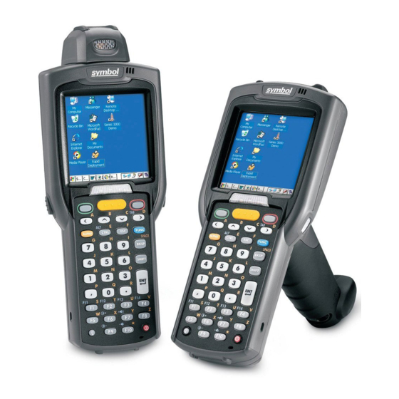
Getting Started 1-5 Parts There are three versions of the MC3000 mobile computers, the MC3000 1D/2D Imager (MC3000-K or MC3090-K), the MC3000 Laser with Rotating Scan Turret (MC3000-R or MC3090-R) and the MC3090 Gun (MC3090-G). For more information on the Rotating Scan... -
Page 26: Rotating Scan Turret
MC3000-K Figure 1-2. MC3000 Imager (MC3000-K) and MC3000 Laser (MC3000-R) Mobile Computers (back view) Rotating Scan Turret The MC3000-R mobile computer features a Rotating Scan Turret with three position stops. This feature offers greater scanning flexiblilty. Position Stop Position Stop Position Stop Figure 1-3. -
Page 27: Mobile Computer Startup
Getting Started 1-7 Scan LED Charge LED Beeper Indicators Indicator (red/green) (amber) Indicator LED Bar Display Scan Button Keypad Power Scan LED Indicator (red/green) Trigger Figure 1-4. MC3090-G Mobile Computer Mobile Computer Startup To start using the mobile computer: • Install the main battery. •... - Page 28 MC3000 Integrator Guide 3. Insert the battery into the slot, bottom first and press the battery gently into the slot. The battery clip locks the battery into place. 4. With the latches in the open position, replace the Strap/Door Assembly, top first and press to close.
- Page 29 Getting Started 1-9 Latches Strap/Door Hand Strap Assembly Battery Strap/Door Assembly Figure 1-6. Main Battery Installation (MC3090-G)
-
Page 30: Battery Charging
The main battery can be charged before insertion into the mobile computer or after it is installed. There are two main batteries for the MC3000, the Standard Battery and the Extended Life Battery. Either battery can be used, but the Extended Life Battery requires a different Strap/Door Assembly. -
Page 31: Spare Battery Charging
Getting Started 1-11 Table 1-2. Mobile Computer LED Charge Indicators Indication Mobile computer not placed correctly in the cradle; cable not connected correctly; charger is not powered. Fast Blinking Amber Error in charging; check placement of the mobile computer. Slow Blinking Amber Mobile computer is charging. -
Page 32: Starting The Mobile Computer
MC3000 Integrator Guide Starting the Mobile Computer When the mobile computer is powered on for the first time, it initializes. The Symbol Splash screen appears for a short period of time, followed by the Calibration screen. Figure 1-7. Symbol Splash Screen After the calibration procedure is performed the factory default settings launch the Demo window. -
Page 33: Demo Window
The Demo window is the factory default menu. On initial power up (or on a warm or cold boot) the Demo window appears. These sample/demo applications are intended to be used by application developers as application development examples. These applications were not developed to support end users. Refer to the Symbol Application Guide for information about the Demo window applications. -
Page 34: Resetting The Mobile Computer
1. Press and simultaneously hold 7, 9 and Power. Do not hold down any other keys or buttons. 2. As the mobile computer initializes MC3000 Demo window appears. Files that remain open during a warm boot may not be retained. -
Page 35: Waking The Mobile Computer
Getting Started 1-15 Waking the Mobile Computer The wakeup conditions are configurable and the current factory default settings are subject to change/update. The mobile computer wakeup configuration is set in the registry file. Table 1-3 lists the default wakeup conditions settings. Table 1-3. -
Page 36: Main Battery Removal
3. Release battery: a. On the MC3000-K/R, release the battery clip (at the top of the battery) and lift the battery out top first. b. On the MC3090-G, pull the battery pull tab to unclip the battery and lift the battery out top first. If the battery does not have a pull tab, use the stylus to unclip the battery and then lift the battery. - Page 37 Getting Started 1-17 Latches Strap/Door Assembly Battery Pull Tab Battery Battery without Pull Tab Battery with Pull Tab Figure 1-11. Main Battery Removal (MC3090-G)
-
Page 38: Strap/Door Assembly Removal And Replacement
1-18 MC3000 Integrator Guide Strap/Door Assembly Removal and Replacement The Strap/Door Assembly consists of a hand strap and the battery door. There are two versions of this assembly, one for the Standard Battery and one for the Extended Life Battery. Before removing the Strap/Door Assembly, press the red Power button to turn off the screen and set the mobile computer to suspend mode. -
Page 39: Strap/Door Assembly Removal And Replacement (Mc3090-G)
Getting Started 1-19 Strap/Door Assembly Removal and Replacement (MC3090-G) The Strap/Door Assembly consists of a hand strap and the battery door. Before removing the Strap/Door Assembly, press the red Power button to turn off the screen and set the mobile computer to suspend mode. To remove the Strap/Door Assembly: 1. -
Page 40: File System Directory Structure
1-20 MC3000 Integrator Guide File System Directory Structure The mobile computer directory structure displays all of the file folders. The pre-installed folders are in flash file system memory and optional removable storage devices (SD storage cards). Figure 1-14. Mobile Computer Directory Structure •... - Page 41 Accessories Chapter Contents Introduction ................2-3 Cradles .
- Page 42 MC3000 Integrator Guide Setup................2-14 Spare Battery Charging .
-
Page 43: Introduction
Accessories 2-3 Introduction The MC3000 accessories provide a variety of product support capabilities. Accessories include cradles, cables, spare battery chargers and SD cards. Cradles • Single Slot Serial/USB cradle charges the mobile computer main battery and/or a spare battery. It also synchronizes the mobile computer with a host computer through either a serial or a USB connection. -
Page 44: Single Slot Serial/Usb Cradle
USB Connection Setup on page 2-32. Use only a Symbol approved power supply output rated 12 VDC and minimum 3.3 A. Use of an alternative power supply will void the product warranty and may cause product damage. See the MC3000 User Guide for the power supply regulatory compliance statement. -
Page 45: Battery Charging
The Single Slot Serial/USB cradle can charge the mobile computer main battery and a spare battery simultaneously. To charge the mobile computer: 1. Connect the Single Slot Serial/USB cradle to a Symbol approved power source. 2. Slide the mobile computer into the mobile computer slot. The amber Charge LED Indicator indicates the mobile computer battery charging status. -
Page 46: Led Charge Indications
MC3000 Integrator Guide LED Charge Indications The Single Slot Serial/USB cradle uses the amber Charge LED Indicator to indicate MC3000 battery charging status and the Spare Battery Charging LED to indicate spare battery charging status. See Table 2-1 for charging status indications. -
Page 47: Four Slot Charge Only Cradle
• Simultaneously charges up to four mobile computers. Use only a Symbol approved power supply output rated 12 VDC and minimum 9 A. Use of an alternative power supply will void the product warranty and may cause product damage. See the MC3000 User Guide for the power supply regulatory compliance statement. -
Page 48: Battery Charging
The Four Slot Charge Only cradle can charge up to four mobile computers simultaneously. To charge the mobile computer: 1. Connect the Four Slot Charge Only cradle to a Symbol approved power source. 2. Slide the mobile computer into the mobile computer slot. -
Page 49: Four Slot Ethernet Cradle
Figure 2-5. Four Slot Ethernet Cradle Connection Ethernet Cradle Drivers The Ethernet cradle drivers are pre-installed on the MC3000 and initiate automatically when the MC3000 is placed in a properly connected Four Slot Ethernet cradle. When the mobile computer is inserted into the Four Slot Ethernet cradle, the LAN icon indicates that the mobile computer is... - Page 50 2-10 MC3000 Integrator Guide Double-tap the LAN icon to open the LANNDS1 window. This window display the TCP/IP information for the mobile computer. LAN Icon Figure 2-6. LANNDS1 Window...
-
Page 51: Charging And Communication
Accessories 2-11 Charging and Communication Insert the mobile computer into a slot to begin charging and initiate communication. Charge LED Indicator (amber) Scan/Charge Indicator LED Bar Mobile Computer Slot Speed LED Link LED Figure 2-7. Four Slot Ethernet Cradle LED Charge Indications The charge LED shows the status of the battery charging in the mobile computer. -
Page 52: Daisychaining Ethernet Cradles
2-12 MC3000 Integrator Guide Daisychaining Ethernet Cradles To connect several cradles to an Ethernet network, up to four (recommended maximum) Ethernet cradles may be daisychained. The Speed LED and the Link LED on the Ethernet port 2 function in the same way as the Speed LED and the Link LED on the front of the cradle. -
Page 53: Wall Mount Bracket
Accessories 2-13 Wall Mount Bracket Use the optional Wall Mount Bracket to mount a four slot cradle directly to a wall. To attach the Wall Mount Bracket: 1. Use the Wall Mount Bracket as a template and mark the locations of the four mounting screws. Use fasteners appropriate for the type of wall and the Wall Mount Bracket, mounting slots. - Page 54 2-14 MC3000 Integrator Guide 6. Align the Wall Mount Bracket mounting tabs with the mounting slots in the back of the four slot cradle. Slip the two mounting tabs into mounting slots. 7. Swing the four slot cradle down onto the mounting bracket and align the mounting screws so that they fit into the screw slots.
-
Page 55: Four Slot Spare Battery Charger
The Four Slot Spare Battery Charger simultaneously charges up to four spare batteries. Use only a Symbol approved power supply output rated 12 VDC and minimum 3.3 A. Use of an alternative power supply will void the product warranty and may cause product damage. See the MC3000 User Guide for the power supply regulatory compliance statement. -
Page 56: Spare Battery Charging
2-16 MC3000 Integrator Guide Spare Battery Charging To charge up to four MC3000 spare batteries: 1. Insert the spare battery into the spare battery charging slot, bottom first. 2. Pivot the top of the battery down onto the contact pins. -
Page 57: Cables
• USB Client Charge cable (standard-A connector and a barrel receptacle for power). Use only a Symbol approved power supply output rated 5.4 VDC and minimum 3 A. Use of an alternative power supply will void the product warranty and may cause product damage. See the MC3000 User Guide for the power supply regulatory compliance statement. -
Page 58: Setup
To charge the mobile computer battery: 1. Connect the MC3000 Communication/Charge cable power input connector to the Symbol approved power source. 2. Attach the bottom of the mobile computer to the MC3000 connector and gently press in until the snaps latch on the mobile computer. -
Page 59: Universal Battery Charger (Ubc) Adapter
Reference Guide, p/n 70-33188-xx. Use only a Symbol approved power supply output rated 15 VDC and minimum 1.5 A. Use of an alternative power supply will void the product warranty and may cause product damage. See the MC3000 User Guide for the power supply regulatory compliance statement. -
Page 60: Ubc Adapter Led Charge Indications
2-20 MC3000 Integrator Guide 2. Pivot the top of the battery down onto the contact pins. Battery Battery Clip UBC Adapter Spare Battery Charging Slot Figure 2-18. UBC Adapter Battery Insertion 3. Gently press down on the battery to ensure proper contact. The Standard Battery usually charges in less than four hours and the Extended Life Battery usually charges in less than six hours. -
Page 61: Secure Device Card
Accessories 2-21 Secure Device Card The Secure Device (SD) card provides secondary non-volatile storage (the flash memory is slower than RAM). The SD card holder is located under the battery. Follow proper Electro-Static Discharge (ESD) precautions to avoid damaging the SD card. Proper ESD precautions include, but are not limited to, working on an ESD mat and ensuring that the operator is properly grounded. -
Page 62: Copy Files Onto The Sd Card
2-22 MC3000 Integrator Guide Copy Files onto the SD Card The SD card can be used to store files or programs used by the mobile computer. Files may be copied using an available file browser, or using ActiveSync. InkWiz is a provided tool that is being used as an example of how to access data on the SD card. -
Page 63: Delete A File From The Sd Card
Accessories 2-23 5. Tap the Edit - Paste to paste the file into the Storage Card partition. The Storage Card partition now shows that the MSIMGSIZ.DAT file is in the Storage Card partition. Figure 2-23. InkWiz, Paste File Delete a File From The SD Card InkWiz is a provided tool that can be used to delete data from the SD card. -
Page 64: Format An Sd Card
2-24 MC3000 Integrator Guide Format an SD Card Use the Storage Manager to format the SD card. 1. Tap Start - Settings -Control Panel to access the Windows Control Panel. Figure 2-25. Windows Control Panel 2. Double tap the Storage Manager icon to access the Storage Properties Window. - Page 65 Accessories 2-25 5. If the SD card does not have an existing partition, tap New. The Create New Partition dialog box appears. If a partition exists, proceed to step 7. Figure 2-27. Create New Partition Window 6. In the Name: text box enter a partition name, and tap OK. The Storage Properties window appears. Figure 2-28.
- Page 66 2-26 MC3000 Integrator Guide 9. Tap Properties, the Partition Properties window appears. Figure 2-29. Partition Properties 10. Tap Format, the Format window appears. Figure 2-30. Format Windows 11. The default settings for the Format window are to perform a Quick Format. To perform a full format tap the Quick Format check box to uncheck.
- Page 67 Accessories 2-27 13. Tap Yes, the Format in progress window appears. Figure 2-32. Format In Progress Window 14. The Format in progress window completion bar indicates the status of the format. When the format is complete the Format complete window appears with a Format Complete message. Figure 2-33.
- Page 68 2-28 MC3000 Integrator Guide 16. Tap OK, the Storage Properties window appears. Figure 2-35. Storage Properties Window 17. Tap OK, to exit the Storage Manager.
-
Page 69: Serial/Usb Communication
ActiveSync installation procedures. Communication Setup The communication setup procedures for the Single Slot Serial/USB cradle and the MC3000 Communication/Charge cables are provided in this section as an example. The serial communication setup procedures are provided in, Serial Communication Setup on... -
Page 70: Serial Communication Setup
The serial communication setup is used to set up to communicate between the host and the mobile computer using either a Single Slot Serial/USB cradle or using one of the serial MC3000 Communication/Charge cables. For serial communication using the Single Slot Serial/USB cradle, connect only the serial cable, do not connect both the serial cable and the USB cable. - Page 71 Accessories 2-31 7. In the ActiveSync window, select File - Connection Settings, the Connection Settings window appears. 8. Select the appropriate COM port for the host computer. Figure 2-38. Serial Connection Setting 9. Tap OK to save any changes made. Every mobile computer should have a unique device name.
-
Page 72: Usb Connection Setup
The USB communication setup is used to set up to communicate between the host and the mobile computer using either a Single Slot Serial/USB cradle or using one of the serial MC3000 Communication/Charge cables. For serial communication using the Single Slot Serial/USB cradle, connect only the USB cable, do not connect both the USB cable and the serial cable. -
Page 73: Cradle/Cable Setup
USB(s). 12. Upon connection, synchronization occurs automatically. Cradle/Cable Setup To use ActiveSync with a cradle or a MC3000 Communication/Charge cable, see Serial Connection Setup on page 2-30 Connection Setup on page 2-32 for communication setup procedures. - Page 74 2-34 MC3000 Integrator Guide...
-
Page 75: Setting Up An Activesync Connection On The Host Computer
ActiveSync Chapter Contents Introduction ................3-3 Mobile Computer Setup . - Page 76 MC3000 Integrator Guide...
-
Page 77: Introduction
ActiveSync 3-3 Introduction To communicate with various host devices, install Microsoft ActiveSync (version 3.7 or higher) on the host computer. Use ActiveSync to synchronize information on the mobile computer with information on the host computer. Changes made on the mobile computer or host computer appear in both places after synchronization. -
Page 78: Setting Up An Activesync Connection On The Host Computer
MC3000 Integrator Guide Microsoft recommends installing ActiveSync on the host computer before connecting the mobile computer. Before setting up a partnership between the mobile computer and host computer. See the Chapter 2, Accessories for a list of the accessories that can be used. -
Page 79: Setting Up A Partnership
ActiveSync 3-5 Setting up a Partnership After ActiveSync installation is complete, the ActiveSync Setup Wizard sets up a partnership to synchronize information between the mobile computer and host computer and customize synchronization settings. To set up a partnership: 1. Connect the mobile computer to the host computer using an accessory described in Chapter 2, Accessories. - Page 80 MC3000 Integrator Guide 5. Click the Standard partnership radio button and then select Next. The New Partnership/Specify how to synchronize data window appears. Figure 3-6. How To Sync Window 6. Click the Synchronize with this desktop computer radio button and select Next. The New Partnership/Select Number of Partnerships window appears.
- Page 81 ActiveSync 3-7 7. Click the Yes, I want to synchronize with only this computer radio button and then select Next. The New Partnership/Select Synchronization Settings window appears. Figure 3-8. Select Synchronization Settings Window 8. To synchronize a particular type of information, select its check box. To stop synchronization of that information, clear its check box.
- Page 82 MC3000 Integrator Guide 10. Select Finish. The Connected window appears confirming the connection between the mobile computer and the host. Figure 3-10. ActiveSync Connected Window During the first synchronization, information stored on the host computer is copied to the mobile computer. When the copy is complete and all data is synchronized, the mobile computer can be disconnected from the host computer.
- Page 83 Software Installation on Development PC Contents Introduction ................4- 3 Required System Configurations .
- Page 84 MC3000 Integrator Guide...
-
Page 85: Introduction
• Device Configuration Package (DCP) for MC3000. The SMDK for C is a development tool used to create native C and C++ applications for all Symbol mobile computers. It includes documentation, header files (.H), and library files (.LIB) for native code application development that targets Symbol value-add APIs. -
Page 86: Components
Used to configure the mobile computer. \Program Files\Symbol Device Configuration Packages\MC3000\v1.0\Flash flash partitions Folders Hex image - default Loads onto the mobile computer for configuration. \Program Files\Symbol Device Configuration Packages\MC3000\v1.0\Hex Images location Documentation Documents that provide guidance on using and \Program Files\Symbol Device Configuration Packages\MC3000\v1.0 integrating the MC3000. - Page 87 6. Locate the .exe file on the development computer, double-click the executable file and follow the install screen prompts. 7. Once installed, access the components of the SMDK for C from the Symbol Mobility Developer Kit for C program group of the Windows Start menu.
-
Page 88: Components
Components The sample applications provide examples of how to interface with the Symbol API functions. To build a sample application, open the Samples folder from the Windows Start menu. Open the folder for the desired sample and then open the project file. The project file has an extension of VCP. -
Page 89: Adding Programs
Software Installation on Mobile Computer Introduction ................5-3 ActiveSync . - Page 90 MC3000 Integrator Guide...
-
Page 91: Introduction
Software Installation on Mobile Computer 5-3 Introduction With the appropriate accessory, software, and connection, the mobile computer can share information with the host computer. This chapter provides information about installing software and files on the mobile computer. Download/software installations can be performed using: •... -
Page 92: Adding Programs
MC3000 Integrator Guide 4. Select Explore. Figure 5-2. ActiveSync Explorer 5. Double-click the folder to expand the folder contents. Figure 5-3. Application Folder Contents 6. Use Explorer to locate the host computer directory that contains the file to download. Tap that directory in the left pane to display its contents in the right pane. -
Page 93: Adding A Program From The Internet
Software Installation on Mobile Computer 5-5 1. Download the program to the host computer (or insert the CD or disk that contains the program into the host computer). The program may consist of a single *.xip file, *.exe file, a *.zip file, or a Setup.exe file. 2. - Page 94 MC3000 Integrator Guide...
- Page 95 Creating/Loading Hex Images Introduction ................6-3 Starting Terminal Configuration Manager.
- Page 96 MC3000 Integrator Guide...
-
Page 97: Introduction
Using standard windows drag and drop operations, files can be added and deleted from the script window. The DCP includes scripts used by Symbol Technologies to build the standard factory installed Platform and Application partitions provided on the mobile computer. The standard Platform partition contains drivers while the Application partition contains demo applications and optional components. -
Page 98: Starting Terminal Configuration Manager
Starting Terminal Configuration Manager Click the Start - Programs - Symbol - Symbol Device Configuration Packages - MC3000 C42V1.0 to start TCM. The TCM window appears displaying two child windows: Script1 and File Explorer. The Script1 window contains a newly created script and the File Explorer window contains a file explorer view used for selecting files to be placed in the script. - Page 99 Creating/Loading Hex Images 6-5 Table 6-1. TCM Components (Continued) Icon Component Function Small icons button View the current script items as small icons. List button View the current script items as a list. Details button View the current script items with more details. About button Display version information for TCM.
-
Page 100: Defining Script Properties
MC3000 Integrator Guide Defining Script Properties Before a script is created, the script properties must be defined. This defines the type of mobile computer, flash type, number of disks being created and the memory configuration of each disk partition. To define the script properties: 1. -
Page 101: Creating The Script For The Hex Image
Modifications to a script file can be saved using the Save or the Save As function. Saving changes to an existing script writes over the original script. To use an original or Symbol supplied standard script as a base, use the Save As function to save the script using... -
Page 102: Building The Image
MC3000 Integrator Guide Building the Image Once the script is created, the hex image defined by the script can be built. As part of the build, TCM performs a check on the script which verifies that all files referenced in the script exist. This check is important for previously created scripts to ensure that files referenced in the script are still in the designated locations. -
Page 103: Sending The Hex Image
1. For downloads using either a serial or a USB connection, connect the mobile computer to the development computer using the Single Slot Serial/USB cradle or MC3000 Communication/Charge cables. 2. Press and hold a yellow Scan button and the Power button simultaneously until the mobile computer resets into IPL. - Page 104 6-10 MC3000 Integrator Guide Table 6-2. IPL Menu Partitions Partition Name Description Platform Contains the files in the Platform folder. Application Contains the files in the Application folder. Config Block Contains information to correctly configure the operating system for the mobile computer. This information is loaded by the manufacturer.
- Page 105 Creating/Loading Hex Images 6-11 5. IPL displays the Select Transport menu which lists the available methods of downloading the file. Select Transport Lighthouse 0 - Serial Previous Figure 6-7. Select Transport Menu 6. Use the up and down scroll keys to select either the erial transport method or the USB transport method, then Lighthouse 0 - S press ENT.
- Page 106 12. For serial or USB port connections, click the Serial tab and select the Image Files To Load. The USB: Symbol Device option will not appear on the Comm Port drop-down list until after the Waiting for Download message has completed.
- Page 107 Creating/Loading Hex Images 6-13 17. When complete, Device Status displays Result was: Success!, or in the case of an error, the cause of the error. Downloading: “Partition Name” via “Device Parameters” Result was: Success! Press any key to continue Figure 6-11. Downloading Complete Screen 18.
-
Page 108: Tcm Error Messages
6-14 MC3000 Integrator Guide TCM Error Messages TCM validates the cells in the partition table when the Execute button is clicked. Cells highlighted in red contain an error. Partition loading is disabled until all errors are corrected. Table 6-3. TCM Error Messages... -
Page 109: Ipl Error Detection
Creating/Loading Hex Images 6-15 IPL Error Detection While receiving data, IPL performs many checks on the data to ensure that the data is received correctly. If an error is detected, IPL immediately aborts the download, and reports the error on an error screen. Error screens may vary depending on the action being performed. - Page 110 Error Text Error Number Probable Cause Insufficient data available to A Symbol HEX file download was attempted but the HEX file is invalid. Ensure the file is in Symbol HEX complete record file format. Invalid Symbol HEX file A Symbol HEX file download was attempted but the HEX file is invalid. Ensure the file is in Symbol HEX file format.
-
Page 111: Creating A Splash Screen
Creating a Splash Screen The source bitmap files used to create the default splash screens for the mobile computer are supplied with the DCP for MC3000 These files can be modified using any of the standard windows image editors, allowing customization for particular customers. -
Page 112: Flash Storage
The two FFS partitions appear as two separate folders in the Windows CE file system and are as follows: • Platform: The Platform FFS partition contains Symbol-supplied programs and Dynamic Link Libraries (DLLs). This FFS is configured to include DLLs that control system operation. Since these drivers are required for basic mobile computer operation, only experienced users should modify the content of this partition. -
Page 113: Copyfiles
“>”. The following example from the file application.cpy is contained on the demo application partition included in the DCP for MC3000. It can also be obtained from the Symbol web site at http://devzone.symbol.com/. -
Page 114: Ipl
6-20 MC3000 Integrator Guide IPL allows the user to upgrade the mobile computer with software updates and/or feature enhancements. Partition Update vs. File Update There are two types of updates supported by the mobile computer: partitions and files. The file system used by the mobile computer is the same as the file system used on a desktop computer. - Page 115 Wireless Applications Contents Introduction ................7- 3 Signal Strength Icon.
- Page 116 MC3000 Integrator Guide Manage Profiles Application ..................7-23 Changing Profiles .
-
Page 117: Chapter 7. Wireless Applications
Wireless Applications 7-3 Introduction Wireless LANs allow mobile computers to communicate wirelessly and to send captured data to a host device in real time. Before a mobile computer can be used on a Spectrum24 WLAN, the facility must be set up with the required hardware to run the wireless LAN and the mobile computer must be properly configured. -
Page 118: Find Wlans Application
MC3000 Integrator Guide Find WLANs Application Use the Find WLANs application to discover available networks in the vicinity of the user and mobile computer. To open the Find WLANs application, tap the Signal Strength icon - Find WLANs. The Find WLANs window displays. -
Page 119: Profile Editor Wizard
Wireless Applications 7-5 Tap-and-hold on a WLAN network to launch a context sensitive menu. The menu provides two options: Connect and Refresh. Select Refresh to refresh the WLAN list. Wireless profiles may also be created from one of the listed networks by selecting a network from the list and then selecting Connect. -
Page 120: Operating Mode
For a single profile that can be used in multiple countries, with infrastructure that supports 802.11d (including Symbol infrastructure), set the Profile Country to Allow Any Country. Under Options - Regulatory, select Enable 802.11d. The Options - Regulatory - Country setting is not used. -
Page 121: Ad-Hoc
Wireless Applications 7-7 Ad-Hoc Use the Ad-Hoc dialog box to select the necessary information to control Ad-Hoc mode. This dialog box does not display if Infrastructure mode is selected. To Select Ad-Hoc mode: 1. Select a channel number from the Channel drop-down list. The default is Channel 1 (2412 MHz). Figure 7-5. -
Page 122: Tunneled Authentication
MC3000 Integrator Guide Tunneled Authentication Use the Tunneled Authentication dialog box to select the tunneled authentication options. There are different selections available for PEAP or TTLS authentication. To select a tunneled authentication type Figure 7-7. Tunneled Auth Dialog Box 1. Tap a tunneled authentication type from the drop-down list. - Page 123 Wireless Applications 7-9 Table 7-8 lists the TTLS tunneled authentication options. Table 7-8. TTLS Tunneled Authentication Options TTLS Tunneled Authentication Description CHAP Challenge Handshake Authentication Protocol (CHAP) is one of the two main authentication protocols used to verify the user name and password for PPP Internet connections.
-
Page 124: User Certificate Selection
7-10 MC3000 Integrator Guide User Certificate Selection If the User Certificate check box on the Tunneled Authentication dialog box is checked or if TLS is the selected authentication type, then the Installed User Certificates dialog box displays. The user is required to select a certificate before proceeding. Select a certificate from the drop-down list of currently installed certificates. - Page 125 Wireless Applications 7-11 1. Tap the down arrow on the drop-down list to display the list of currently installed certificates. 2. Tap a certificate to select and its name appears in the drop-down list. 3. Tap the Install Certificate button to install a certificate. Figure 7-10.
-
Page 126: Credential Cache Options
7-12 MC3000 Integrator Guide A confirmation dialog displays verifying the installation. If the information in this dialog is correct, tap the Yes button, If the information in this dialog is not correct tap the No button. The wizard returns to the Installed Server Certs dialog box. - Page 127 Wireless Applications 7-13 • EAP TLS • PEAP • LEAP • TTLS. If the At Time check box is selected the TIme Cache Options dialog box displays. Figure 7-14. Time Cache Options Dialog Box 1. Tap the Interval radio button to check credentials at a set time interval. 2.
-
Page 128: Password
7-14 MC3000 Integrator Guide The user name and password can be entered (but is not required) when the profile is created. When a profile authenticates with credentials that were entered in the profile, caching rules do not apply. Caching rules only apply on credentials that are entered through the login dialog box. - Page 129 Wireless Applications 7-15 Figure 7-18. Advanced Identity Dialog Box Tap Next, the Encryption dialog box displays.
-
Page 130: Encryption
7-16 MC3000 Integrator Guide Encryption Use the Encryption dialog box to select an encryption type. The Encryption dialog box only allows encryption types that can be used with the currently selected authentication type. See Table 7-11 for the encryption types available with each authentication type. -
Page 131: Key Entry Page
Wireless Applications 7-17 Table 7-11. Encryption / Authentication Matrix Encryption Authentication Open TKIP TTLS Key Entry Page If either 40-Bit WEP or 128-Bit WEP is selected the wizard proceeds to the key entry dialog box unless the Use Passkey check box was selected in the Encryption Dialog Box (see Figure 7-19 on page 7-16). -
Page 132: Ip Mode
7-18 MC3000 Integrator Guide When a user selects None as an authentication and TKIP as an encryption, the user is forced to enter a passkey. The user cannot enter a passkey if the encryption is TKIP and the authentication is anything other than None. -
Page 133: Ip Address Entry
Wireless Applications 7-19 IP Address Entry Use the IP Address Entry dialog box to enter the IP address and subnet information. Figure 7-24. Static IP Address Entry Dialog Box Table 7-13. Static IP Address Entry Fields Field Description IP Address The Internet is a collection of networks with users that communicate with each other. -
Page 134: Transmit Power
7-20 MC3000 Integrator Guide Table 7-14. IP Config Advanced Address Entry Fields Field Description The default Gateway is a device that is used to forward IP packets to and from a remote destination. The Domain Name System (DNS) is a distributed Internet directory service. DNS is used mostly to translate domain names and IP addresses. -
Page 135: Battery Usage
Wireless Applications 7-21 Figure 7-27. Transmit Power Dialog Box (Ad-Hoc Mode) Table 7-16. Power Transmit Options (Ad-Hoc Mode) Field Description Full Select Maximum power to set the mobile computer to the highest transmission power level. Select Maximum power when operating in highly reflective environments and areas where other devices could be operating nearby. -
Page 136: Manage Profiles Application
7-22 MC3000 Integrator Guide Power consumption is also related to the transmit power settings. Table 7-17. Battery Usage Options Field Description Continuous Aware Mode (CAM) provides the best network performance, but yields the shortest battery life. Fast Power Save performs in the middle of CAM and MAX Power Save with respect to network Fast Power Save performance and battery life. -
Page 137: Changing Profiles
Wireless Applications 7-23 Table 7-18. Profile Icons Profile is currently in use and describes an ad-hoc profile using encryption. Profile is not valid in the device current operating regulatory domain. The profiles are listed in priority order for use by the automatic roaming feature. Change the order by moving profiles up or down. Edit existing profiles by selecting one in the list and then tap-and-hold to display the menu. -
Page 138: Export A Profile
7-24 MC3000 Integrator Guide Export a Profile To export a profile to a registry file, select a profile from the list and select Export from the pop-up menu. The save As dialog box displays with the Application folder and a default name of WCS_PROFILE{profile GUID}.reg (Globally Unique Identifier). -
Page 139: Wireless Status Application
Wireless Applications 7-25 Wireless Status Application The Wireless Status application window displays the current wireless connection status and information about the wireless connection. To open the Wireless Status window, tap the Signal Strength icon - Wireless Status. The Wireless Status window displays. Figure 7-31. -
Page 140: Signal Strength Window
7-26 MC3000 Integrator Guide Signal Strength Window The Signal Strength window provides information about the connection status of the current wireless profile that includes signal quality, missed beacons and transmit retry statistics. The BSSID address (shown as “AP MAC Address) displays the AP currently associated with the connection. - Page 141 Wireless Applications 7-27 Table 7-19. Signal Strength Status Field Description Signal Level The AP signal level in decibels per milliwatt (dBm). Noise Level The background interference (noise) level in decibels per milliwatt (dBm). The access point/mobile computer Signal to Noise Ratio (SNR) of signal strength to noise (interference) in decibels per milliwatt (dBm).
-
Page 142: Current Profile Window
7-28 MC3000 Integrator Guide Current Profile Window The Current Profile window displays basic information about the current profile and connection settings. This window updates every two seconds. To open the Current Profile window, tap Current Profile in the Wireless Status window. The Current Profile window displays. -
Page 143: Ipv4 Status Window
Wireless Applications 7-29 IPv4 Status Window The IPv4 Status window displays the current IP address, subnet and other IP related information assigned to the mobile computer. It also allows the address to be renewed if it the profile is currently using DHCP to obtain the IP information. When the user tap Renew a full DHCP discover initiates. -
Page 144: Wireless Log Window
7-30 MC3000 Integrator Guide Wireless Log Window The Wireless Log window displays a log of important recent activity, such as authentication, association, DHCP renewal completion, in time order. Users can choose to save the log to a file or to clear the log (within this instance of the application only). There is also an auto scroll feature to automatically scroll down when new items are added to the log. -
Page 145: Versions Window
Wireless Applications 7-31 Versions Window The Versions window displays software, firmware and hardware version numbers. This window only updates each time it is displayed. There is no need to update constantly. The content of the window is determined at runtime, along with the actual hardware and software to display in the list. -
Page 146: Wireless Diagnostics Application
7-32 MC3000 Integrator Guide Wireless Diagnostics Application The Wireless Diagnostics application window provides links to perform ICMP Ping, Trace Routing and Known APs. To open the Wireless Diagnostics window, tap the Signal Strength icon - Wireless Diagnostics. The Wireless Diagnostics window displays. -
Page 147: Icmp Ping Window
Wireless Applications 7-33 ICMP Ping Window The ICMP Ping window allows a user to test a connection at the network layer (part of the IP protocol), between the mobile computer and an AP. Ping tests only stop when the user taps the Stop Test button, closes the Wireless Diagnostics application, or if the mobile computer switches between infrastructure and ad-hoc modes. -
Page 148: Trace Route Window
7-34 MC3000 Integrator Guide Trace Route Window Trace Route traces a packet from a computer to a host, showing how many hops the packet requires to reach the host and how long each hop takes. The Trace Route utility identifies where the longest delays are occurring. -
Page 149: Known Aps Window
Wireless Applications 7-35 Known APs Window The Known APs window displays the APs in range using the same ESSID as the mobile computer. This window only available when in the Infrastructure mode. To open the Known APs window, tap Known APs in the Wireless Diagnostics window. The Known APs window displays. Figure 7-40. -
Page 150: Options
7-36 MC3000 Integrator Guide Options Use the wireless Option dialog box to select various operation settings. The options are saved when Save is tapped. If the user taps X before saving and an option was changed, a dialog box displays asking the user to close without saving the changes. -
Page 151: Regulatory Options
Wireless Applications 7-37 Regulatory Options Use the Regulatory settings to configure the country the mobile computer is in. Due to regulatory requirements (within a country) a mobile computer is only allowed to use certain channels. Figure 7-42. Regulatory Options Dialog Box Table 7-23. -
Page 152: System Options
Select Auto Time Config check box to enable automatic update of the system time. The device time is updated during network association, based on the time as set in the AP. This proprietary feature is only supported with Symbol infrastructure. Enabled by Auto Time Config default. -
Page 153: Change Password Dialog Box
Wireless Applications 7-39 Change Password Dialog Box Use the Change Password dialog box to require a password before any profile can be edited. This allows system administrators to pre-configure profiles and not allow a user to change the network settings. The user could also use this feature to protect their settings from a guest user. - Page 154 7-40 MC3000 Integrator Guide 1. Tap Export Options. The Save As dialog box displays. Figure 7-47. Export Options Save As Dialog Box 2. The default folder is \Application\FusionApps\Certs\. 3. In the Name field, enter a file name. 4. Tap OK.
-
Page 155: Cold Boot Persistence
Wireless Applications 7-41 To export all profiles: 1. Tap Export All Profiles. The Save As dialog box displays. Figure 7-48. Export All Profiles Save AS Dialog Box 2. Navigate to the desired folder. 3. In the Name field, enter a file name. 4. -
Page 156: Registry Settings
7-42 MC3000 Integrator Guide Registry Settings Some of the parameters can be modified through a registry key. The registry path is: HKLM\SOFTWARE\Symbol Technologies, Inc.\Configuration Editor Table 7-26. Registry Parameter Settings Type Default Description CertificateDirectory REG_SZ \\Windows The default directory to find certificates. -
Page 157: Login, Log Off Application
Wireless Applications 7-43 Login, Log Off Application When the user launches the login, log off application, the mobile computer may be in two states; the user may already be logged onto the mobile computer (having already entering credentials through the login box) or the user is not logged on. Each of these states have a separate set of use cases and a different look to the dialog box. -
Page 158: No User Logged In
7-44 MC3000 Integrator Guide No User Logged In To access user profiles, when no user is logged in, launch the login dialog box and login. The dialog displays differently if it is: • Launched by WCS, when the service is connecting to a new profile that needs credentials •... - Page 159 AirBEAM Smart Chapter Contents Introduction ................8-3 AirBEAM Package Builder .
- Page 160 MC3000 Integrator Guide...
-
Page 161: Introduction
The AirBEAM Smart Client package that is included on the mobile computer does not include a licence key. This software version is limited to downloading of specific Symbol software products. A license key can be purchased that will allow the downloading of... -
Page 162: Configuring The Airbeam Smart Client
MC3000 Integrator Guide Configuring the AirBEAM Smart Client 1. Select Start - Programs - AirBEAM Client. The AirBEAM CE window appears. 2. Tap File - Configure. The AirBEAM configuration window appears. Figure 8-1. AirBEAM Smart Configuration Window The configuration window is used to view and edit AirBEAM Smart Client configurations. This dialog box has six tabs that can be modified - Packages(1), Packages(2), Server, Misc(1), Misc(2) and Misc(3). -
Page 163: Server Tab
AirBEAM Smart 8-5 Server Tab This tab is used to specify the configurations of the server to which the client connects during the package synchronization process. Table 8-3. Server Tab Field Description IP Address The IP Address of the server. It may be a host name or a dot notation format. Directory The directory on the server that contains the AirBEAM Smart package definition files. -
Page 164: Misc(2) Tab
MC3000 Integrator Guide Table 8-4. Misc (1) Tab (Continued) Field Description WNMS This checkbox specifies whether the AirBEAM Smart Client uploads a WNMS information file at the end of each version synchronization. Misc(2) Tab This tab is used to configure various miscellaneous features. -
Page 165: Synchronizing With The Server
AirBEAM Smart 8-7 Table 8-6. Misc (3) Tab (Continued) Field Description Use DHCP bootfile This check box control specifies whether the AirBEAM Smart Client uses the DHCP response option 67 to specify the Package and Package 1 parameters. If enabled, special RF network registry settings are required to force the DHCP server to return the "Bootfile name" field (option 67). The special RF network registry settings are included, but commented out, in the radio network registry initialization files (essid_xxxx_yy.reg). - Page 166 MC3000 Integrator Guide • The AirBEAM staging utility provides a simple single dialog user interface that is used to quickly start the software installation process.
-
Page 167: Chapter 9. Rapid Deployment Client
Rapid Deployment Client Chapter Contents Introduction ................9-3 Rapid Deployment Window . - Page 168 MC3000 Integrator Guide...
-
Page 169: Introduction
Rapid Deployment Client 9-3 Introduction The Rapid Deployment (RD) Client facilitates software downloads to a mobile device from a Mobility Services Platform (MSP) Console FTP server. The MSP Console is a web-based interface to the wireless infrastructure monitoring and management tools provided by the MSP Lite or MSP Enterprise server. - Page 170 MC3000 Integrator Guide Table 9-1. Rapid Deployment Window Text Box/Button Description Please scan all of the bar codes... This text box displays the status of a scanned bar code. - Waiting indicates the device is ready to scan a bar code.
-
Page 171: Scanning Rd Bar Codes
Rapid Deployment Client 9-5 Scanning RD Bar Codes When the mobile computer scans and successfully decodes a single or multiple RD bar codes, the data encoded in the bar code can: • Reset the device connection profile. A connection profile is a set of Mobile Companion parameters that the device uses to access the wireless network. - Page 172 MC3000 Integrator Guide If the mobile computer cannot connect to the server, it continues to retry until the user cancels (exits) the application. If failure to connect to the server persists, see the MSP Administrator. 5. When configuration is complete: a.
- Page 173 Maintenance & Troubleshooting Contents Introduction ................10- 3 Maintaining the Mobile Computer.
- Page 174 10-2 MC3000 Integrator Guide...
-
Page 175: Introduction
Maintenance & Troubleshooting 10-3 Introduction This chapter includes instructions on cleaning and storing the mobile computer, and provides troubleshooting solutions for potential problems during mobile computer operation. Maintaining the Mobile Computer For trouble-free service, observe the following tips when using the mobile computer: •... -
Page 176: Troubleshooting
10-4 MC3000 Integrator Guide Troubleshooting Mobile Computer Table 10-1. Troubleshooting the Mobile Computer Problem Cause Solution Mobile computer does not turn Main battery not charged. Charge or replace the main battery in the mobile computer. Main battery not installed Ensure the battery is installed properly... - Page 177 Verify that the mobile computer is loaded with a scanning application. accept scan input. loaded. Unreadable bar code. Ensure the symbol is not defaced. Distance between scan Ensure the mobile computer is within proper scanning range. window and bar code is incorrect.
-
Page 178: Single Slot Serial/Usb Cradle
10-6 MC3000 Integrator Guide Single Slot Serial/USB Cradle Table 10-2. Troubleshooting the Single Slot Serial/USB Cradle Problem Cause Solution Mobile computer amber Charge Cradle is not receiving power. Ensure the power cable is connected securely to both the cradle and to AC LED Indicator does not light power. -
Page 179: Four Slot Charge Only Cradle
Maintenance & Troubleshooting 10-7 Four Slot Charge Only Cradle Table 10-3. Troubleshooting the Four Slot Charge Only Cradle Problem Cause Solution Mobile computer amber Charge LED Cradle is not receiving power. Ensure the power cable is connected securely to both the cradle Indicator does not light when mobile and to AC power. -
Page 180: Four Slot Spare Battery Charger
10-8 MC3000 Integrator Guide Four Slot Spare Battery Charger Table 10-5. Troubleshooting the Four Slot Spare Battery Charger Problem Cause Solution Spare Battery Charging LED Spare battery is not correctly Remove and re-insert the spare battery into the charging slot, ensuring it is correctly does not light when spare seated. -
Page 181: Cables
Ensure the power cable is connected securely to both the cable and to AC power. LED Indicator does not light Mobile computer is not seated Remove and re-insert the mobile computer into the MC3000 connector, ensuring it is when mobile computer correctly in the cable. - Page 182 10-10 MC3000 Integrator Guide...
- Page 183 Technical Specifications Appendix Contents Mobile Computer And Accessory Technical Specifications ........A-3 Mobile Computer Pin-Outs.
- Page 184 MC3000 Integrator Guide...
-
Page 185: Mobile Computer And Accessory Technical Specifications
7.60 in L x 3.18 in W x 6.54 in D (193 mm L x 80.8 mm W x 166 mm H) Weights MC3000-R (with standard battery)* - 12.9 oz (366 g) MC3000-K (with extended battery)* - 14.6 oz (414 g) MC3090-G (with extended battery)* - 18.6 oz (527 g) *For WLAN mobile computers add approximately 0.5 oz (14 g). - Page 186 RSS expanded, RSS limited and RSS-14Maxi Code (UPS), Data matrix (electronics industry, US Planet (USPS), UK 4-state, Australian 4-state, Canadian 4-state, Japanese 4-state, Dutch Kix *Go to http://software.symbol.com/ for a list of the latest supported symbologies. SD cards Select SD cards with environmental and/or the write cycle performance specifications that meet or exceed the application requirements.
-
Page 187: Mobile Computer Pin-Outs
Technical Specifications A-5 Mobile Computer Pin-Outs Figure A-1. MC3000 Connector Table A-3. MC3000 Pin-Outs PIN Number Signal Name Function Ground/Return CRADLE_IN* When grounded, the mobile computer detects it is in the cradle. RS232 DCD (into mobile computer) USB_N USB negative... -
Page 188: Laser Decode Ranges
The minimum element width (or “symbol density”) is the width in mils of the narrowest element (bar or space) in the symbol. The maximum usable length of a symbol at any given range is shown below. - Page 189 Technical Specifications A-7 MC3000-R Laser Decode Ranges Table A-5. Ranges Symbol Density/ Bar Code Content/ Bar Code Type/W-N Ratio Contrast (Note 1) Near 5.0 mil ABCDEFGH+ 2.0 in 4.9 in Code 39; 2.5:1 80% MRD 5.08 cm 12.45 cm 7.5 mil ABCDEF 1.6 in...
-
Page 190: Imager Decode Ranges
The minimum element width (or “symbol density”) is the width in mils of the narrowest element (bar or space) in the symbol. The maximum usable length of a symbol at any given range is shown below. - Page 191 Technical Specifications A-9 MC3000-K Imager Decode Ranges Table A-7. Ranges Symbol Density/ Bar Code Content/ Bar Code Type/W-N Ratio Contrast (Note 1) Near 5.0 mil ABCDEFGH+ 4.5 in 6.5 in Code 39; 2.5:1 80% MRD 11.43 cm 16.51cm 7.5 mil ABCDEF 3.3 in...
- Page 192 A-10 MC3000 Integrator Guide...
- Page 193 Glossary 802.11/802.11abg A radio protocol that may be used by the Symbol radio card. Access Point Access Point (AP) refers to Symbol’s Ethernet Access Point. It is a piece of communications equipment that manages communications between the host computer system and one or more wireless terminals.
- Page 194 Bar Width Thickness of a bar measured from the edge closest to the symbol start character to the trailing edge of the same bar. Binary digit. One bit is the basic unit of binary information. Generally, eight consecutive bits compose one byte of data.
- Page 195 Those characters available for encoding in a particular bar code symbology. Check Digit A digit used to verify a correct symbol decode. The scanner inserts the decoded data into an arithmetic formula and checks that the resulting number matches the encoded check digit.
- Page 196 Communication port; ports are identified by number, e.g., COM1, COM2. Continuous Code A bar code or symbol in which all spaces within the symbol are parts of characters. There are no intercharacter gaps in a continuous code. The absence of gaps allows for greater information density.
- Page 197 Glossary GL-5 Flash Memory Flash memory is responsible for storing the system firmware and is non-volatile. If the system power is interrupted the data is not be lost. Gateway Address An IP address for a network gateway or router. A mobile computer may be part of a subnet as specified by its IP address and Netmask.
- Page 198 It is broadcast by the cellular device when accessing the cellular system. Misread (Misdecode) A condition which occurs when the data output of a reader or interface controller does not agree with the data encoded within a bar code symbol.
- Page 199 100%. Quiet Zone A clear space, containing no dark marks, which precedes the start character of a bar code symbol and follows the stop character. Random Access Memory. Data in RAM can be accessed in random order, and quickly written and read.
- Page 200 The mirror-like direct reflection of light from a surface, which can cause difficulty decoding a bar code. Spring Radio Protocol A radio protocol that may be used by the Symbol radio card. Symbol Radio cards that use the Spring protocol also have an Net ID.
- Page 201 Glossary GL-9 Symbol Length Length of symbol measured from the beginning of the quiet zone (margin) adjacent to the start character to the end of the quiet zone (margin) adjacent to a stop character. Symbology The structural rules and conventions for representing data within a particular bar code type (e.g.
- Page 202 GL-10 MC3000 Integrator Guide...
-
Page 203: Index
....... . 8-3 MC3000 communication/charge cables configuring ......8-4 battery charging . - Page 204 ... .2-14 MC3000 communication/charge cables ..2-17 data backup ......1-10 UBC adapter .
- Page 205 ....1-3 MC3000-K parts ......1-5, 1-6 battery charging .
- Page 206 Symbol splash screen ..... . . 1-12 RD bar codes ......9-5 Symbol support center .
- Page 207 Index IN-5 saving script ......6-7 starting ....... 6-4 technical specifications .
- Page 208 IN-6 MC3000 Integrator Guide...
-
Page 209: Tell Us What You Think
We’d like to know what you think about this Manual. Please take a moment to fill out this questionnaire and fax this form to: (631) 738-3318, or mail to: Symbol Technologies, Inc. One Symbol Plaza M/S B-4 Holtsville, NY 11742-1300 Attention: Technical Publications Manager IMPORTANT: If you need product support, please call the appropriate customer support number provided. - Page 212 Symbol Technologies, Inc. One Symbol Plaza Holtsville, New York 11742-1300 http://www.symbol.com 72E-68900-02 Revision A - November 2005...