Symbol MC909X Integrator Manual
Hide thumbs
Also See for MC909X:
- User manual (246 pages) ,
- User manual (244 pages) ,
- User manual (21 pages)
Table of Contents
Advertisement
Quick Links
Advertisement
Table of Contents
Troubleshooting

Related Manuals for Symbol MC909X


Summary of Contents for Symbol MC909X
- Page 1 MC909X Mobile Computer Integrator Guide...
- Page 3 MC909X Integrator Guide 72E-72216-03 Rev. A April 2006...
-
Page 4: Patents
Symbol reserves the right to make changes to any software or product to improve reliability, function, or design. Symbol does not assume any product liability arising out of, or in connection with, the application or use of any product, circuit, or application described herein. -
Page 5: Revision History
About This Guide Revision History Changes to the original manual are listed below: Change Date Description -01 Rev. A 11/22/05 Initial Release -02 Rev A 1/15/2006 Add MC909X-K/S and Windows Mobile 5.0 support. -03 Rev A 2/15/2006 Add MC9097 information. - Page 6 MC909X Integrator Guide...
-
Page 7: Table Of Contents
Configurations........................ i-xv Chapter Descriptions ..................... xv Notational Conventions....................xvi Related Documents and Software ................. xvi Service Information ......................xvii Symbol Support Center.................... xviii Chapter 1: Getting Started Introduction ........................1-1 Unpacking the Mobile Computer ................... 1-1 Accessories ........................1-5 Getting Started ......................1-6 Installing and Removing the Main Battery .............. - Page 8 MC909X Integrator Guide Performing a Clean Boot ................... 1-13 SIM Card........................1-15 Stylus ..........................1-17 MC9090-G Strap ......................1-18 Battery Management ....................1-21 Battery Saving Tips ....................1-21 Changing the Power Settings ..................1-21 Changing the Display Backlight Settings ............... 1-22 Changing the Keypad Backlight Settings ..............
- Page 9 Table of Contents Serial/USB Connection ................... 2-22 Using the MSR ......................2-22 Cable Adapter Module ....................2-24 Attaching and Removing ..................2-24 Setup ........................2-25 Battery Charging Indicators ..................2-26 Serial/USB Connection ................... 2-26 Universal Battery Charger (UBC) Adapter ..............2-27 Inserting and Removing a Battery ................
- Page 10 MC909X Integrator Guide Chapter 4: Wireless Applications Introduction ........................4-1 Signal Strength Icon ..................... 4-2 Turning the WLAN Radio On and Off ................4-3 Windows Mobile 5.0 ....................4-3 Windows CE 5.0 ..................... 4-3 Find WLANs Application ....................4-5 Profile Editor Wizard .....................
- Page 11 Table of Contents Change Password ....................4-39 Export ........................4-40 Persistence ........................4-41 Registry Settings ......................4-42 Log On/Off Application....................4-43 User Already Logged In ..................4-43 No User Logged In ....................4-43 Device Username Field ..................4-43 Chapter 5: MC9094 Configuration Introduction ........................
- Page 12 Chapter 7: Application Deployment for WinCE 5.0 Software Installation on Development PC ..............7-1 DCP for MC9090 ..................... 7-1 Platform SDK ......................7-2 Symbol Mobility Developer Kits ................7-2 Installing Other Development Software ..............7-2 Deployment ........................7-2 ActiveSync ......................7-2 SD Card ........................
- Page 13 Table of Contents Rapid Deployment Window ..................7-24 Scanning RD Bar Codes ..................7-25 AirBEAM Smart ......................7-27 AirBEAM Package Builder ..................7-27 AirBEAM Smart Client ..................... 7-27 AirBEAM License ....................7-27 Configuring the AirBEAM Smart Client ............. 7-28 Packages(1) Tab..................7-28 Packages(2) Tab..................
- Page 14 Synchronizing with the Server ................8-23 Manual Synchronization ..................8-23 Automatic Synchronization ................8-24 AirBEAM Staging ....................8-24 Symbol Mobility Developer Kits ..................8-24 Chapter 9: Maintenance & Troubleshooting Introduction ........................9-1 Maintaining the Mobile Computer ................. 9-1 Troubleshooting ......................9-2 Mobile Computer .....................
-
Page 15: About This Guide
NOTE Screens and windows pictured in this guide are samples and can differ from actual screens. Documentation Set The documentation set for the MC909X is divided into guides that provide information for specific user needs. Microsoft Application Guide - describes how to use Microsoft developed applications. - Page 16 MC909X Integrator Guide...
-
Page 17: Configurations
About This Guide Configurations This guide covers the following configurations: Data Operating Configuration Radios Display Memory Keypads Capture System MC9090-G WLAN - 802.11a/b/g Color or 64 MB RAM/ Laser, Long Windows CE 5.0 28-key, monochrome 64 MB Flash Range 43-key, WPAN - Bluetooth Laser, or 53-key,... -
Page 18: Notational Conventions
Chapter 7, Application Deployment for WinCE 5.0, provides instructions for installing the Device • Configuration Package (DCP) for MC909X and the SMDK for C on the host computer.and downloading software and files to the mobile computer. Chapter 8, Application Deployment for Mobile 5.0, describes new features in Windows Mobile 5.0... -
Page 19: Service Information
Call the Support Center from a phone near the equipment so that the service person can try to talk through the problem. If the equipment is found to be working properly and the problem is symbol readability, the Support Center will request samples of bar codes for analysis at our plant. -
Page 20: Symbol Support Center
MC909X Integrator Guide Symbol Support Center For service information, warranty information or technical assistance contact or call the Symbol Support Center Country/Region Address Telephone United States Symbol Technologies, Inc. 1-800-653-5350 One Symbol Plaza Holtsville, New York 11742-1300 Canada Symbol Technologies Canada, Inc. - Page 21 315-271700 (Inside Netherlands) Netherlands Kerkplein 2, 7051 CX +31-315-271700 (Outside Netherlands) Postbus 24 7050 AA Varsseveld, Netherlands Norge/Norway Symbol’s registered and mailing address: +47 2232 4375 Symbol Technologies Norway Hoybratenveien 35 C N-1055 OSLO, Norway Symbol’s repair depot and shipping address:...
- Page 22 Call Center: +46 8 445 29 29 (international) Box 1354 Support E-Mail: Sweden.Support@se.symbol.com S-171 26 SOLNA Sweden Visit/shipping address: Symbol Technologies AB Solna Strandväg 78 S-171 54 SOLNA Sweden If you purchased your Symbol product from a Symbol Business Partner, contact that Business Partner for service.
-
Page 23: Chapter 1 Getting Started
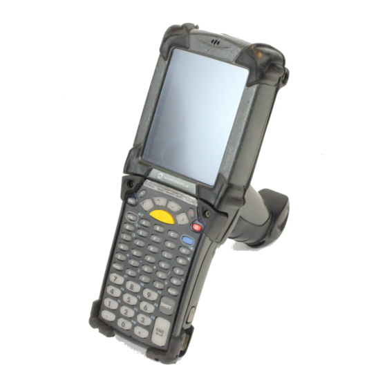
• Quick Start Guide (poster). • Inspect the equipment for damage. If you are missing any equipment or if you find any damaged equipment, contact the Symbol Technologies Support Center immediately. See Symbol Support Center on page xviii contact information. - Page 24 1 - 2 MC909X Integrator Guide Microphone (Windows Indicator LED Bar Touch Screen Mobile 5.0 only) Scan Button Keypad Headphone Jack (Windows Mobile 5.0 only) Power Button Trigger Handstrap MC9090-G Figure 1-1...
-
Page 25: Getting Started
Scan Button Scan Button or Walkie-Talkie Button Keypad on MC9097-K Battery Release Latch Exit Window Exit Window Headphone Stylus Jack Scan Button or Scan Scan Button Walkie-Talkie Button Button Stylus (MC9097-K) Strap SIM Door MC9090-K MC9094-K MC9097-K MC909X-K Figure 1-2... - Page 26 1 - 4 MC909X Integrator Guide Microphone Touch Screen Indicator LED Bar Power Button Scan Button Scan Button or Walkie-Talkie Button Keypad on MC9097-S Exit Window Exit Window Stylus Headphone Jack Scan Scan Scan Button or Button Button Walkie-Talkie Button on...
-
Page 27: Accessories
Getting Started 1 - 5 Accessories Table 1-1 lists the accessories available for the MC909X. MC909X Accessories Table 1-1 Accessory Description Cable Adapter Module Snap-on required to connect the following cables to the mobile computer. (CAM) AC line cord (country-specific) and power supply, charges the mobile •... -
Page 28: Getting Started
1 - 6 MC909X Integrator Guide MC909X Accessories (Continued) Table 1-1 Accessory Description Stylus Performs pen functions. Universal Battery Charger Adapts the UBC for use with the Series 9000 batteries. Adapter Wall Mounting Bracket and Use for wall mounting applications. -
Page 29: Charging The Battery
Getting Started 1 - 7 Installing the Main Battery Figure 1-4 Charging the Battery Charging the Main Battery and Memory Backup Battery Before using the mobile computer for the first time, charge the main battery until the amber charge indicator light remains lit (see Table 1-2 on page 1-8 for charge status indications). -
Page 30: Charging The Main Battery
NOTE To achieve the best battery life in mobile computers with multiple radios, turn off the radios that are not being used. This can be accomplished via the SetDevicePower() API (refer to the SMDK Help File for Symbol Mobile Computers) or via the Control Panel application (tap Start > 9000 Demo > Ctl Panel icon). -
Page 31: Charging Spare Batteries
Getting Started 1 - 9 Charging Spare Batteries Use the following three accessories to charge spare batteries: Single Slot Serial/USB Cradle • Four Slot Spare Battery Charger • UBC Adapter. • To charge a spare battery: Ensure the accessory used to charge the spare battery is connected to the appropriate power source (see Chapter 2, Accessories for setup information). -
Page 32: Starting The Mobile Computer
NOTE When a battery is fully inserted in a mobile computer for the first time, upon the mobile computer’s first power up, the device boots and powers on automatically. When the mobile computer is powered on for the first time, it initializes its system. The Symbol splash screen (Figure... -
Page 33: Calibrating The Screen
Getting Started 1 - 11 MC9090/4 MC9097 Symbol Splash Window Figure 1-7 Calibrating the Screen To calibrate the screen so the cursor on the touch screen aligns with the tip of the stylus: Using the stylus carefully press and briefly hold the tip of stylus on the center of each target that appears on the screen. -
Page 34: Resetting The Mobile Computer
1 - 12 MC909X Integrator Guide Resetting the Mobile Computer Windows CE 5.0 Devices There are two reset functions, warm boot and cold boot. A warm boot restarts the mobile computer by closing all running programs. A cold boot also restarts the mobile computer, but erases all stored records and entries in RAM. Data saved in flash memory or a memory card is not lost. -
Page 35: Performing A Warm Boot
A clean boot resets the mobile computer to the factory default settings. All data is the folder is Application retained. You must download the Clean Boot Package file from the Symbol DevZone and install on the mobile computer. To perform a clean boot: Download the Clean Boot Package from the Symbol DevZone. -
Page 36: Sim Card
On an MC9090-G, while the battery is partially released, simultaneously press and release the trigger and the Power button. On an MC909X-K or MC909X-S, while the battery is partially released, simultaneously press and release the left scan button and the Power button. -
Page 37: Sim Card
Getting Started 1 - 15 Door Removing SIM Door Figure 1-8 Unlock the SIM holder by sliding the metal clip to the open position. Lift the SIM holder. SIM Holder Unlock SIM Case Figure 1-9 Insert the SIM card, as shown in Figure 1-10, with the cut edge of the card facing the top of the mobile computer and the contacts facing down. - Page 38 1 - 16 MC909X Integrator Guide Locking the SIM Card Housing Figure 1-11 Replace the SIM door with one screw. Replacing the SIM Door Figure 1-12 Press the red Power button. NOTE On the MC9097, it is not recommended that you swap the SIM card with another SIM card. If you do swap SIM cards, perform step 10.
-
Page 39: Stylus
Getting Started 1 - 17 Stylus Use the mobile computer stylus for selecting items and entering information. The stylus functions as a mouse. Tap: Touch the screen once with the stylus to press option buttons and open menu items. • Tap and Hold: Tap and hold the stylus on an item to see a list of actions available for that item. - Page 40 1 - 18 MC909X Integrator Guide MC909X-K Strap The strap may be moved to either the left or right side of the mobile computer to suit user preferences. To reposition the MC909X-K strap: Lift the loop end of the strap over the button.
- Page 41 The strap may be moved to either the left or right side of the mobile computer to suit user preferences. To reposition the MC909X-S strap, attach the MC909X-S strap to either the left or right side of the mobile computer to suit user preferences. To reposition the strap: Remove the screw securing the bottom of the strap to the device.
-
Page 42: Battery Management
1 - 20 MC909X Integrator Guide Screws Strap Bracket Remove Strap Bracket Figure 1-17 Remove the screw securing the bottom of the strap to the device. Reverse the procedure to re-attach the strap. Battery Management Battery Saving Tips Leave the mobile computer connected to AC power at all times when not in use. -
Page 43: Changing The Display Backlight Settings
Getting Started 1 - 21 Changing the Display Backlight Settings To change the display backlight settings in order to conserve more battery power: On devices with Windows CE 5.0, tap > > > icon > tab. Start Settings Control Panel Backlight Battery Power On devices with Windows Mobile 5.0, tap... -
Page 44: Wlan Radio On Windows Mobile 5.0
1 - 22 MC909X Integrator Guide To turn on the radio: > > > icon > tab. Start Settings Control Panel Power PwrDevices In the text box, scroll down until : displays. WLP1 Select displays in the text box at the top of the window. - Page 45 Getting Started 1 - 23 To turn on the Bluetooth and WWAN radios, tap the icon (on non-WWAN devices) or the Connectivity icon (on WWAN devices) and select Antenna/Signal Turn Off Flight Mode NOTE On the MC9097, wait 20 to 40 seconds for the radio to power on. During this time do not suspend the mobile computer or remove the battery.
- Page 46 1 - 24 MC909X Integrator Guide...
-
Page 47: Chapter 2: Accessories
38-key Alpha keypad (MC909X-S only) • 43-key keypad (MC909X-G and MC909X-K only) • 53-key keypad (MC909X-G and MC909X-K only) • 3270 Emulator keypad (MC909X-G and MC909X-K only) • 5250 Emulator keypad (MC909X-G and MC909X-K only) • VT Emulator keypad (MC909X-G and MC909X-K only). •... -
Page 48: Snap-On Modules
2 - 2 MC909X Integrator Guide Modem Module enables data communication between the mobile computer and a host computer, • remotely through the phone lines, and synchronizes information between the mobile computer and a host computer. Multimedia Card (MMC) provides secondary non-volatile storage. (An SD card may also be used.) •... - Page 49 Accessories 2 - 3 Screws Keypad SD/MMC Card Holder Removing the Keypad Figure 2-1 CAUTION Do not apply more than 4 in-lbs of torque when tightening the keypad screws. Replace the keypad and re-attach using the two screws. Installing the Keypad Figure 2-2 Perform a cold boot.
-
Page 50: Multi Media Card (Mmc) / Secure Device (Sd) Card
The MMC provides secondary non-volatile storage. The MMC is located under the keypad (see Figure 2-1). NOTE SD cards are inter-operable with MMC cards and can also be used in MC909X mobile computers. Do not remove the keypad while the mobile computer is on and do not operate the mobile computer CAUTION with the keypad detached. -
Page 51: Single Slot Serial/Usb Cradle
Accessories 2 - 5 Single Slot Serial/USB Cradle This section describes how to set up and use a single Single Slot Serial/USB cradle with the mobile computer. For serial and USB communication setup procedures see Serial Communication Setup on page 2-47. -
Page 52: Setup
Setup CAUTION Use only a Symbol approved power supply output rated 12 VDC and minimum 3.3 A. Use of an alternative power supply will void the product warranty and may cause product damage. Refer to the MC909X User Guide for the power supply regulatory compliance statement. -
Page 53: Battery Charging Indicators
Accessories 2 - 7 Power Port Serial Port Serial Cable Serial Port DC Cable AC Line Cord Power Supply Single Slot Cradle Power/Serial Connections Figure 2-6 USB Port Power Port DC Cable Power Supply USB Port USB Cable AC Line Cord Single Slot Cradle Power/USB Connections Figure 2-7 Battery Charging Indicators... - Page 54 2 - 8 MC909X Integrator Guide Spare Battery LED Charging Indicators Table 2-1 Spare Battery LED Indication (on cradle) No spare battery in well; spare battery not placed correctly; cradle is not powered. Fast Blinking Amber Error in charging; check placement of spare battery.
-
Page 55: Four Slot Ethernet Cradle
Accessories 2 - 9 Four Slot Ethernet Cradle This section describes how to set up and use a Four Slot Ethernet cradle with the mobile computer. For cradle communication setup procedures see Ethernet Communication Setup on page 2-11. Communication LED Four Slot Ethernet Cradle Figure 2-8 CAUTION... -
Page 56: Setup
Setup CAUTION Use only a Symbol approved power supply output rated 12 VDC and minimum 9 A. Use of an alternative power supply will void the product warranty and may cause product damage. Refer to the MC909X User Guide for the power supply regulatory compliance statement. -
Page 57: Battery Charging Indicators
Update the firmware of MobileDox Net. To install the Cradle Management Software on the host computer, download the latest version of the software from http://devzone.symbol.com. Refer to the instructions included with the software. Installing iDockIt iDockIt is a connection utility which manages activities between the mobile computer and a connected Ethernet cradle. -
Page 58: Mobile Computer Configuration
2 - 12 MC909X Integrator Guide Integrated modem capabilities using TAPI interface. • Runs as a tray application, and always runs in the background. • The ability to configure settings within the application. • Options to change parameters upon docking (with or without settings time-out). -
Page 59: Modifying Cradle Settings
Accessories 2 - 13 To set the IP address: Launch the MobileDox Cradle Manager on the host computer. Click > . The Set IP Address window appears: File Set IP Address of Unlisted Device Set IP Address Window Figure 2-10 Enter the appropriate MAC Address and IP address. - Page 60 2 - 14 MC909X Integrator Guide Cradle Settings - General Settings Fields Table 2-3 Field Description Device Name A text string used to describe the MobileDox device. Any 15-character string may be entered. Custom String A text string for any desired usage (examples are: location, asset ID, etc.).
- Page 61 Accessories 2 - 15 Cradle Settings Window - Port Settings Tab Figure 2-13 Cradle Settings - Port Settings Fields Table 2-5 Field Description Port Name A text string used to describe the device attached to the port. Any 15-character string can be entered. You can specify up to four port names, one for each of the cradle’s slots.
-
Page 62: Four Slot Charge Only Cradle
2 - 16 MC909X Integrator Guide Four Slot Charge Only Cradle This section describes how to set up and use a Four Slot Charge Only cradle with the mobile computer. Four Slot Charge Only Cradle Figure 2-14 Do not place coins, keys or paper clips in cradle well. -
Page 63: Setup
Setup CAUTION Use only a Symbol approved power supply output rated 12 VDC and minimum 9 A. Use of an alternative power supply will void the product warranty and may cause product damage. Refer to the MC909X User Guide for the power supply regulatory compliance statement. -
Page 64: Four Slot Spare Battery Charger
2 - 18 MC909X Integrator Guide Four Slot Spare Battery Charger This section describes how to set up and use the Four Slot Spare Battery Charger to charge up to four spare batteries. MC909X-S Battery Short Battery Adapter Spare MC909X-G/K Battery... -
Page 65: Setup
Setup CAUTION Use only a Symbol approved power supply output rated 15 VDC and minimum 5 A. Use of an alternative power supply will void the product warranty and may cause product damage. Refer to the MC909X User Guide for the power supply regulatory compliance statement. -
Page 66: Magnetic Stripe Reader
2 - 20 MC909X Integrator Guide Magnetic Stripe Reader This section describes how to set up and use the snap-on MSR with the mobile computer. The MSR snaps on to the bottom of the mobile computer and can be easily removed when not in use. -
Page 67: Attaching And Removing
Setup CAUTION Use only a Symbol approved power supply output rated 12 VDC and minimum 3.3 A. Use of an alternative power supply will void the product warranty and may cause product damage. Refer to the MC909X User Guide for the power supply regulatory compliance statement. -
Page 68: Battery Charging Indicators
The MSR9000 sample application is designed to work with the MSR. This sample application illustrates how an application should handle MSR inputs (refer to the Symbol Application Guide for Symbol Devices). NOTE The MSR does not need to be attached to the power supply to read magnetic stripes. - Page 69 Accessories 2 - 23 Power on the mobile computer. > > > to start the sample application. Start 9000 Demo Test Apps MSR 9000 MSR Cameo Swipe the magnetic stripe card through the MSR, ensuring the magnetic stripe on the card faces the mobile computer.
-
Page 70: Cable Adapter Module
2 - 24 MC909X Integrator Guide Cable Adapter Module This section describes how to set up and use the snap-on CAM with the mobile computer. The CAM snaps on to the bottom of the mobile computer and can be easily removed when not in use. -
Page 71: Setup
Setup CAUTION Use only a Symbol approved power supply output rated 12 VDC and minimum 3.3 A. Use of an alternative power supply will void the product warranty and may cause product damage. Refer to the MC909X User Guide for the power supply regulatory compliance statement. -
Page 72: Battery Charging Indicators
2 - 26 MC909X Integrator Guide Serial Port To Device Serial/USB Port CAM Serial Connection Figure 2-26 Battery Charging Indicators To charge the mobile computer’s battery through the CAM, connect the power supply to the CAM (see Figure 2-25 on page 2-25), then attach the CAM to the mobile computer. -
Page 73: Universal Battery Charger (Ubc) Adapter
To remove the battery, press the battery release and lift battery out of the well. Setup Use only a Symbol approved power supply output rated 15 VDC and minimum 1.5 A. Use of an CAUTION alternative power supply will void the product warranty and may cause product damage. Refer to the... -
Page 74: Battery Charging Indicators
2 - 28 MC909X Integrator Guide DC Cable AC Line Cord Power Supply UBC Adapter Power Connection Figure 2-28 Battery Charging Indicators To charge a spare battery using the UBC adapter, connect the power supply to the UBC (see Figure 2-28 on page 2-28), then insert the spare battery. - Page 75 Accessories 2 - 29 UBC Adapter Charge LED Status Indications (Continued) Table 2-7 Indication Description STANDBY or Flashing-Yellow The battery was deeply discharged and is being trickle charged to bring the voltage up to the operating level. After operating level voltage is achieved the battery charges normally.
-
Page 76: Modem Module
MC909X mobile computer • Cable Adapter Module (CAM), Symbol p/n ADP9000-100 (see Cable Adapter Module on page 2-24) • Serial Adapter Cable (for communication via cradle), Symbol p/n 25-63856-01 • Microsoft ActiveSync • Setup of host computer and mobile computer. -
Page 77: Setup
Accessories 2 - 31 Setup Connecting to the Mobile Computer Male 15-pin connector Phone port Line In port Phone cord Phone cord Modem Module Connection - Mobile Computer Figure 2-31 CAUTION Do not connect the modem's 15-pin connector into a VGA port of a host computer. Using the Correct Telephone Line Type Use a standard analog phone line, as in most households. -
Page 78: Connecting To The Single Slot Serial/Usb Cradle
2 - 32 MC909X Integrator Guide Connecting to the Single Slot Serial/USB Cradle Adapter cable Male 15-pin connector Line In port Phone port Phone cord Modem Module Connection - Single Slot Serial/USB Cradle Figure 2-32 Do not connect the modem's 15-pin connector into a VGA port of a host computer. - Page 79 Accessories 2 - 33 In the window, select to create a connection. Connections Add a new modem connection Connections Window Figure 2-33 Enter a name for the connection. In the drop-down menu, select , then tap Hayes Compatible on COM1 Next New Connection Window Figure 2-34...
- Page 80 2 - 34 MC909X Integrator Guide NOTE Depending on the location when dialing, additional numbers may need to be dialed (e.g., a 9 prefix is often required if dialing from work; a country code is needed if dialing internationally). To avoid creating new modem connections for each situation, tap use dialing rules to define frequently used dialing locations.
-
Page 81: Configuring The Mobile Computer For The Modem (Windows Ce 5.0)
Configuring the Mobile Computer for the Modem (Windows CE 5.0) To create a modem connection on the mobile computer: Connect the modem to the mobile computer, see Connecting to the Mobile Computer on page 2-31. On the MC909X, tap > . Double-tap the icon. Settings... -
Page 82: Connecting The Modem (Windows Mobile 5.0)
2 - 36 MC909X Integrator Guide Phone Number Window Figure 2-40 NOTE Depending on the location when dialing, additional numbers may need to be dialed (e.g., a 9 prefix is often required if dialing from work; a country code is needed if dialing internationally). To avoid creating new modem connections for each situation, tap use dialing rules to define frequently used dialing locations. -
Page 83: Connecting The Modem (Windows Ce 5.0)
Accessories 2 - 37 Creating a Connection Figure 2-42 Connecting the Modem (Windows CE 5.0) To connect to the host computer using the modem connection created in the last section: > > . Double-tap the icon. Start Settings Control Panel Network and Dialup Connections In the window, double-tap the name of the connection created in Creating a... -
Page 84: Supported Countries
2 - 38 MC909X Integrator Guide Supported Countries Supported Countries Table 2-9 Country Code Country Code Country Code Australia Greece FD or 46 Norway FD or 82 Austria FD or 0A Iceland Portugal FD or 8B Belgium FD or 0F... - Page 85 Accessories 2 - 39 Connections Window Figure 2-44 If entering AT commands for an existing connection, select in the Manage existing connections Connections window. On the tab, select the radio button of the item to edit and tap Modem Edit... New Connection Window Figure 2-45 Tap Next until the...
-
Page 86: Changing The Initialization String (Windows Ce 5.0)
2 - 40 MC909X Integrator Guide My Connection Window - User Information Settings Figure 2-46 Enter AT commands in the text box. See Basic AT Command Syntax Extra dial-string modem commands: on page 2-42. Advanced Window - Extra Dial-String Modem Commands Figure 2-47 Tap ok to exit the Advanced window. - Page 87 Accessories 2 - 41 Network and Connections Windows Figure 2-48 To modify dial-up properties, tap , make the selections in the window. Dial Properties Device Properties To edit the , tap Dialing Patterns Edit Dial-Up and Dial Properties Window Figure 2-49 window appears.
-
Page 88: Basic At Command Syntax
2 - 42 MC909X Integrator Guide Basic AT Command Syntax A command line is made up of three elements: Prefix - consists of the characters “AT” or “at” or, to repeat the execution of the previous command line, • “A/” or “a/”. -
Page 89: Commands
The tables that follow summarize the AT commands, result codes, and S-Registers for the MDM 3000. <string> represents a letter, number, or symbol to be entered. <value> represents a number to be entered. Possible values are listed below the command. - Page 90 2 - 44 MC909X Integrator Guide AT Command Table (Continued) Table 2-10 Country Command Description Specific On during call establishment. Off when receiving carrier. (default) Always on. Off when receiving carrier and during dialing. On during answering. &G Guard tone. &G<value>...
- Page 91 Accessories 2 - 45 S-Register Settings Table 2-11 Default Function Range Units Default Saved Rings to Auto Answer 0-255 rings Ring Counter 0-255 rings Escape Character 0-255 ASCII Carriage Return Character 0-127 ASCII Line Feed Character 0-127 ASCII Backspace Character 0-255 ASCII Wait Time before Blind Dialing or Dial Tone...
- Page 92 2 - 46 MC909X Integrator Guide S-Register Settings (Continued) Table 2-11 Default Function Range Units Default Saved Disconnect Inactivity Timer 0-255 10 S General Bit Mapped Options Status 195 (C0h) LAPM Failure Control Delay Before Forced Hangup 0-255 Flow Control Bit Mapped Options Status...
-
Page 93: Serial Communication Setup
Accessories 2 - 47 Serial Communication Setup The serial communications setup can be used to set up to communicate with a Single Slot Serial/USB Cradle, MSR or a CAM. NOTE For serial communication using accessories that can communicate with either a serial or USB connection, connect only the serial cable. - Page 94 2 - 48 MC909X Integrator Guide Tap ok to exit the window. Connections Ensure that ActiveSync is installed on the host computer and a partnership was created. Select > > on the host computer, if it is not already running. The...
-
Page 95: Serial Connection Setup (Windows Ce 5.0)
Accessories 2 - 49 NOTE The accessory requires a dedicated port. It cannot share a port with any other device. Refer to the host computer user manual supplied to locate the USB ports. Connect the mobile computer to the accessory being used for communication. Power on the mobile computer. - Page 96 2 - 50 MC909X Integrator Guide ActiveSync - Not Connected Figure 2-57 In the window, select > . The window displays. ActiveSync File Connection Settings Connection Settings Connection Settings Figure 2-58 For a serial connection, select check box and select the comm Allow connections to one of the following: port from the drop-down list.
-
Page 97: Usb Host Communication Setup
Accessories 2 - 51 USB Host Communication Setup USB Host mode is only available on Windows Mobile 5.0 devices. NOTE The mobile computer can be configured as a USB host device for use with USB client devices. To configure the mobile computer as a USB host: >... -
Page 98: Wall Mounting Bracket And Shelf Slide
2 - 52 MC909X Integrator Guide Wall Mounting Bracket and Shelf Slide This section describes how to install and set up the MC9000 Wall Mount Bracket and Shelf Slide to mount cradles to a wall. Wall Mounting Bracket Shelf Slides... -
Page 99: Installing The Wall Mount Bracket
Accessories 2 - 53 Installing the Wall Mount Bracket To install the wall mount bracket for use with one or two single slot cradles or four slot chargers, place the smaller surface of the bracket against the wall or vertical support structure, and secure with four 1/4” screws (use two of the three screw holes in each row). -
Page 100: Four Slot Cradle
2 - 54 MC909X Integrator Guide Secure the slide to the bracket by inserting the two pan-head screws provided from below the bracket, up through the bracket’s screw holes and then through the slide’s pan-head screw holes. Secure a second slide to the remaining two screw holes on the bracket in the same manner. - Page 101 Accessories 2 - 55 For two single slot cradle/four slot chargers, slide one onto the left-hand slide, and one onto the right-hand slide. Insert set screws Attaching Two Shelf Slides Figure 2-66 For a four slot cradle, slide the cradle on to the slides, across both brackets. Secure each cradle or charger to its slide using the two set screws provided.
- Page 102 2 - 56 MC909X Integrator Guide...
-
Page 103: Chapter 3: Activesync
ActiveSync Chapter 3 Chapter 3 Chapter 3 ActiveSync Introduction To communicate with various host devices, install Microsoft ActiveSync (version 4.1 or higher) on the host computer. Use ActiveSync to synchronize information on the mobile computer with information on the host computer. -
Page 104: Mobile Computer Setup
3 - 2 MC909X Integrator Guide Mobile Computer Setup NOTE Microsoft recommends installing ActiveSync on the host computer before connecting the mobile computer. The mobile computer can be set up to communicate either with a serial connection or a USB connection. -
Page 105: Setting Up An Activesync Connection On The Host Computer
ActiveSync 3 - 3 ActiveSync Window Figure 3-2 > Menu Connections Select the connection type from the drop-down list. to exit the window and tap to exit the window. Connections ActiveSync Proceed with installing ActiveSync on the host computer and setting up a partnership. Setting Up an ActiveSync Connection on the Host Computer To start ActiveSync: Select... -
Page 106: Setting Up A Partnership With A Windows Ce 5.0 Device
3 - 4 MC909X Integrator Guide Connection Settings Window Figure 3-4 Select the appropriate check box for the type of connection used. Select the check box. Show status icon in Taskbar Select to save any changes made. Setting up a Partnership with a Windows CE 5.0 Device To set up a partnership with a Windows CE 5.0 device:... - Page 107 ActiveSync 3 - 5 Select Synchronization Setting Window Figure 3-6 Select the appropriate settings and click Next Setup Complete Window Figure 3-7 Click Finish...
-
Page 108: Synchronization With A Windows Mobile 5.0 Device
NOTE The first ActiveSync operation must be performed with a local, direct connection. To retain partnerships after a cold boot, capture partnership registry information in a .reg file and save it in the Flash File System, detailed information is provided in the SMDK Windows CE Help File for Symbol Mobile Computers. - Page 109 ActiveSync 3 - 7 Synchronization Setup Wizard Window Figure 3-9 Click Next Synchronization Directly With a Server Window Figure 3-10 Select the check box to synchronize with a server running Microsoft Exchange. Click Next...
- Page 110 3 - 8 MC909X Integrator Guide Synchronization Option Window Figure 3-11 Select the appropriate settings and click Next Wizard Complete Window Figure 3-12 Click Finish...
- Page 111 ActiveSync 3 - 9 ActiveSync Connected Window Figure 3-13 During the first synchronization, information stored on the mobile computer is copied to the host computer. When the copy is complete and all data is synchronized, the mobile computer can be disconnect from the host computer.
- Page 112 3 - 10 MC909X Integrator Guide...
-
Page 113: Chapter 4 Wireless Applications
Wireless Local Area Networks (LANs) allow mobile computers to communicate wirelessly and send captured data to a host device in real time. The MC909X mobile computer supports the IEEE 802.11a, 802.11b and 802.11g standards. Before using the mobile computer on a WLAN, the facility must be set up with the required hardware to run the wireless LAN and the mobile computer must be configured. -
Page 114: Signal Strength Icon
4 - 2 MC909X Integrator Guide Signal Strength Icon icon in the task tray indicates the mobile computer’s wireless signal strength as follows: Signal Strength Wireless Applications Icons, Signal Strength Descriptions Table 4-1 Icon Status Action Excellent signal strength Wireless LAN network is ready to use. -
Page 115: Turning The Wlan Radio On And Off
Wireless Applications 4 - 3 Turning the WLAN Radio On and Off Windows Mobile 5.0 To turn the WLAN radio off tap the icon and select Signal Strength Disable Radio Disable Radio Figure 4-2 To turn the WLAN radio on tap the icon and select Signal Strength Enable Radio... - Page 116 4 - 4 MC909X Integrator Guide To turn the WLAN radio on: > > > icon > tab. Start Settings Control Panel Power PwrDevices In the text box, scroll down until : displays. WLP1 Select displays in the text box at the top of the window.
-
Page 117: Find Wlans Application
Wireless Applications 4 - 5 Find WLANs Application Use the application to discover available networks in the vicinity of the user and mobile computer. Find WLANs To open the application, tap the icon > . The window Find WLANs Signal Strength Find WLANs Find WLANs displays. -
Page 118: Profile Editor Wizard
4 - 6 MC909X Integrator Guide Encryption Icon Table 4-3 Icon Description No encryption. WLAN is an infrastructure network. WLAN is an Ad-Hoc network. WLAN access is encrypted and requires a password. Tap-and-hold on a WLAN network to open a pop-up menu which provides two options:... -
Page 119: Operating Mode
Wireless Applications 4 - 7 NOTE Two profiles with the same user friendly name are acceptable but not recommended. . The Operating Mode dialog box displays. Next Operating Mode Use the dialog box to select the operating mode (Infrastructure or Ad-Hoc) and the country Operating Mode location. - Page 120 For a Options Regulatory Country single profile that can be used in multiple countries, with infrastructure that supports 802.11d (including Symbol infrastructure), set the Profile Country to Allow Any Country Under > , select . The >...
-
Page 121: Ad-Hoc
Wireless Applications 4 - 9 Ad-Hoc Use the dialog box to select the required information to control mode. This dialog box does not Ad-Hoc Ad-Hoc appear if you selected mode. To select Ad-Hoc mode: Infrastructure Select a channel number from the drop-down list. -
Page 122: Tunneled Authentication
4 - 10 MC909X Integrator Guide Authentication Options (Continued) Table 4-6 Authentication Description PEAP Select this option to enable PEAP authentication. This method uses a digital certificate to verify and authenticate a user's identity. LEAP Select this option to enable LEAP authentication, which is based on mutual authentication. -
Page 123: User Certificate Selection
Wireless Applications 4 - 11 Table 4-8 lists the TTLS tunneled authentication options. TTLS Tunneled Authentication Options Table 4-8 TTLS Tunneled Description Authentication CHAP Challenge Handshake Authentication Protocol (CHAP) is one of the two main authentication protocols used to verify the user name and password for PPP Internet connections. -
Page 124: User Certificate Installation
4 - 12 MC909X Integrator Guide Installed User Certificates Dialog Box Figure 4-10 User Certificate Installation To install a user certificate (EAP TLS only) and a server certificate for EAP TLS and PEAP authentication: . The dialog box appears. Install Certificate... - Page 125 Wireless Applications 4 - 13 Installed Server Certificates Dialog Box Figure 4-12 A dialog lists the currently loaded certificate files found in the default directory (\Application\FusionApps\Certs) with the default extension. Browse Server Certificates Figure 4-13 Press the key to change the default path or extension (and search a new path). Select a certificate before tapping the button.
-
Page 126: Credential Cache Options
4 - 14 MC909X Integrator Guide Credential Cache Options If you selected any of the password-based authentication types, you can select different credential caching options. These options specify when the network credential prompts appear: at connection, on each resume, or at a specified time. -
Page 127: Password
Wireless Applications 4 - 15 TTLS. • Selecting the check box displays the dialog box. At Time TIme Cache Options Time Cache Options Dialog Box Figure 4-16 Tap the radio button to check credentials at a set time interval. Interval Enter the value in minutes in the box. -
Page 128: Advanced Identity
4 - 16 MC909X Integrator Guide Password Dialog Box Figure 4-19 Enter a password in the field. Password Select the check box, if advanced identification is required. Advanced ID . The dialog box displays. See Encryption on page 4-17. Next... - Page 129 Wireless Applications 4 - 17 Encryption Dialog Box Figure 4-21 Encryption Options Table 4-10 Encryption Description Open Select Open (the default) when no data packet encryption is needed over the network. Selecting this option provides no security for data transmitting over the network. 40-Bit WEP Select 40-Bit WEP to use 40-bit key length WEP encryption.
-
Page 130: Key Entry Page
4 - 18 MC909X Integrator Guide Encryption / Authentication Matrix Table 4-11 Encryption Authentication Open TKIP PEAP LEAP TTLS Key Entry Page If you select either the wizard proceeds to the key entry dialog box unless the Use 40-Bit WEP... -
Page 131: Ip Address Entry
Wireless Applications 4 - 19 IP Address Entry Use the dialog box to configure network address parameters: IP address, subnet, gateway, IP Address Entry DNS, and WINS. IP Address Entry Dialog Box Figure 4-24 IP Address Entry Table 4-12 Encryption Description DHCP Select Dynamic Host Configuration Protocol (... - Page 132 4 - 20 MC909X Integrator Guide Static IP Address Entry Fields Table 4-13 Field Description IP Address The Internet is a collection of networks with users that communicate with each other. Each communication carries the address of the source and destination networks and the particular machine within the network associated with the user or host computer at each end.
-
Page 133: Transmit Power
Wireless Applications 4 - 21 Transmit Power drop-down list contains different options for Ad-Hoc and Infrastructure mode. Automatic Transmit Power (i.e., use the current AP settings) and Power Plus (use higher than the current AP settings) are available for mode. Infrastructure Adjusting the radio transmission power level enables the user to expand or confine the transmission area with respect to other wireless devices that could be operating nearby. -
Page 134: Battery Usage
4 - 22 MC909X Integrator Guide to display the dialog box. Next Battery Usage Battery Usage Use the dialog box to select power consumption of the wireless LAN. There are three settings Battery Usage available: CAM, Fast Power Save, and MAX Power Save. Battery usage cannot be configured in Ad-Hoc profiles. - Page 135 Wireless Applications 4 - 23 Manage Profiles Window Figure 4-30 Icons next to each profile identify the profile’s current state. Profile Icons Table 4-18 Icon Description No Icon Profile is not selected, but enabled. Profile is disabled. Profile is cancelled. A cancelled profile is disabled until a connect or login function is performed through the configuration editor.
-
Page 136: Changing Profiles
4 - 24 MC909X Integrator Guide Manage Profiles Context Menu Figure 4-31 Changing Profiles A completed profile is a set of configuration settings that can be used in different locations to connect to a wireless network. Create different profiles to have pre-defined operating parameters available for use in various network environments. -
Page 137: Deleting A Profile
Wireless Applications 4 - 25 Manage Profiles - Add Figure 4-33 Select to display the wherein you can set the profile name and ESSID. Set security, network Profile Wizard address information, and power consumption level for the new profile. Deleting a Profile To delete a profile from the list, tap and hold and select from the pop-up menu. -
Page 138: Wireless Status Application
4 - 26 MC909X Integrator Guide Save As Dialog Box Figure 4-34 If required, change the name in the field and tap . A confirmation dialog box appears after the export Name Save completes. Wireless Status Application To open the window, tap the icon >... -
Page 139: Signal Strength Window
Wireless Applications 4 - 27 Quit - exits the window. Wireless Status • Option windows contain a back button to return to the main window. Wireless Status Signal Strength Window window provides information about the connection status of the current wireless profile Signal Strength including signal quality, missed beacons, and transmit retry statistics. -
Page 140: Current Profile Window
4 - 28 MC909X Integrator Guide Signal Strength Status (Continued) Table 4-19 Field Description Tx Retries Displays a percentage of the number of data packets the mobile computer retransmits. The fewer transmit retries, the more efficient the wireless network is. -
Page 141: Ipv4 Status Window
Wireless Applications 4 - 29 Current Profile Window Table 4-20 Field Description Profile Name Displays the current profile name the mobile computer uses to communicate with the AP. ESSID Displays the current profile ESSID name. Mode Displays the current profile mode, either Infrastructure or Ad-Hoc. Authentication Displays the current profile’s authentication type. - Page 142 4 - 30 MC909X Integrator Guide IPv4 Status Fields Table 4-21 Field Description IP Type Displays the IP type for the current profile: . If the IP type is DHCP, leased DHCP Static IP address and network address data appear for the mobile computer. If the IP type is...
-
Page 143: Wireless Log Window
Wireless Applications 4 - 31 Wireless Log Window window displays a log of recent activity, such as authentication, association, and DHCP Wireless Log renewal completion, in time order. Save the log to a file or clear the log (within this instance of the application only). - Page 144 4 - 32 MC909X Integrator Guide Versions Window Figure 4-40 The window displays software version numbers for the following: Configuration Editor • Fusion Build • LoginService • Photon1.0 • WCDiag • WCLaunch • WCSAPI • WCSRV • WCStatus. •...
-
Page 145: Wireless Diagnostics Application
Wireless Applications 4 - 33 Wireless Diagnostics Application application window provides links to perform ICMP Ping, Trace Routing, and Known Wireless Diagnostics APs. To open the window, tap the icon > Wireless Diagnostics Signal Strength Wireless Diagnostics Wireless Diagnostics Window Figure 4-41 window contains the following options. -
Page 146: Trace Route Window
4 - 34 MC909X Integrator Guide ICMP Ping Window Figure 4-42 To perform an ICMP ping: In the field, enter an IP address or select an IP address from the drop-down list. From the drop-down list, select a size value. -
Page 147: Known Aps Window
Wireless Applications 4 - 35 mobile computer and each router appears, along with the total test time. The total test time may be longer than all RTTs added together because it does not only include time on the network. Known APs Window window displays the APs in range using the same ESSID as the mobile computer. -
Page 148: Options
4 - 36 MC909X Integrator Guide Options Use the wireless dialog box to select one of the following operation options from the drop-down list: Option Operating Mode Filtering • Regulatory • Band Selection • System Options • Change Password •... -
Page 149: Regulatory Options
Wireless Applications 4 - 37 Regulatory Options Dialog Box Figure 4-46 Regulatory Options Table 4-24 Field Description Settings Select the country from the drop-down list. To connect to a profile, the profile country must match this setting, or the AP country setting if you selected the Enable 802.11d check box. -
Page 150: Change Password
4 - 38 MC909X Integrator Guide System Options Dialog Box Figure 4-48 System Options Table 4-26 Field Description Profile Roaming Configures the mobile computer to roam to the next available WLAN profile when it moves out of range of the current WLAN profile. -
Page 151: Export
Wireless Applications 4 - 39 Export NOTE For Windows CE 5.0 devices, exporting options enables settings to persists after cold boot. For Mobile 5.0 devices, exporting options enables settings to persists after clean boot. See Persistence on page 4-40 for more information. to export all profiles to a registry file, and to export the options to a registry file. -
Page 152: Persistence
4 - 40 MC909X Integrator Guide Export All Profiles Save As Dialog Box Figure 4-52 Enter a filename in the field. The default filename is WCS_PROFILES.REG. Name: In the drop-down list, select the desired folder. Folder: Save Selecting saves the current profile. This information is used to determine which profile to Export All Profiles connect with after a warm boot or cold boot. -
Page 153: Registry Settings
Wireless Applications 4 - 41 Registry Settings Use a registry key to modify some of the parameters. The registry path is: HKLM\SOFTWARE\Symbol Technologies, Inc.\Configuration Editor Registry Parameter Settings Table 4-27 Type Default Description CertificateDirectory REG_SZ \\Windows The default directory to find certificates. -
Page 154: Log On/Off Application
4 - 42 MC909X Integrator Guide Log On/Off Application When the user launches the application, the mobile computer may be in two states; the user may Log On/Off be logged onto the mobile computer by already entering credentials through the login box, or there are no user logged on. - Page 155 Wireless Applications 4 - 43 Log On/Off Options Table 4-28 Field Description Wireless Profile Field When launching the login application, the Wireless Profile field has available all the wireless profiles that require credentials. This includes profiles that use EAP TLS, PEAP, LEAP, and EAP-TTLS. Profile Status Icon The profile status icon (next to the profile name) shows one of the following states:...
- Page 156 4 - 44 MC909X Integrator Guide...
-
Page 157: Chapter 5 Mc9094 Configuration
(where applicable). Refer to the MC909X User Guide for information on how to use the phone and services. Quick Startup Steps To start using the MC9094 mobile computer for phone and data connections: Install the mobile computer main battery. -
Page 158: Mc9094 Service Verification
5 - 2 MC909X Integrator Guide Configure an GPRS data connection (Configuring an GPRS Data Connection on page 5-3). Configure settings (Phone Settings on page 5-7). Use the phone. MC9094 Service Verification MC9094 phone and data services require a live SIM card, obtained from a service provider, installed in the MC9094 phone/mobile computer. -
Page 159: Configuring An Gprs Data Connection
MC9094 Configuration 5 - 3 Phone Settings Window - Network Tab Figure 5-2 Ensure the service provider’s network appears in the field. Current network: If the network does not appear, tap . If the network still does not appear, verify that the SIM Find Network card was installed correctly. - Page 160 5 - 4 MC909X Integrator Guide Connections Window - Make New Connection Figure 5-4 Enter a connection name in the text box. Enter a name for the connection: Select from the drop-down list. Cellular Line (GPRS) Select a modem: Next...
-
Page 161: Establishing A Data Connection
MC9094 Configuration 5 - 5 Connections Window - User Name & Password Figure 5-6 (user name and password are not required). Finish to exit Connections Establishing a Data Connection Ensure a SIM card is installed in the mobile computer. Ensure an GPRS data connection was configured. See Configuring an GPRS Data Connection on page 5-5. -
Page 162: Ending An Gprs Data Connection
5 - 6 MC909X Integrator Guide Data Connection Figure 5-8 Select Connect Connecting Using GPRS Packet Data Modem Figure 5-9 If the SIM card is protected with a Personal Identification Number (PIN), a dialog box pops up requesting the appropriate PIN to unlock the SIM card. In this case, enter the PIN and tap NOTE Emergency calls can be placed at any time, without requiring a PIN or a SIM card. -
Page 163: Phone Settings
MC9094 Configuration 5 - 7 Connectivity Dialog Box Figure 5-10 Disconnect NOTE When Disconnect is tapped during an active data transfer (e.g., downloading a web page), the GPRS connection automatically reconnects. The GPRS connection cannot be disconnected until the data transfer is complete. -
Page 164: Sounds
5 - 8 MC909X Integrator Guide MC9094 Phone Window - Phone Tab Figure 5-11 Sounds automatically displays on the tab when a live SIM card is installed. Phone Number Phone Select a ring type from the drop-down list. The ring type changes the way the mobile computer Ring type: rings to notify the user of an incoming call. -
Page 165: Changing A Pin
MC9094 Configuration 5 - 9 Enter PIN Figure 5-12 Use the touch keypad to enter a four to eight digit PIN. to enable the PIN and return to the tab. Enter Phone Changing a PIN CAUTION If you enter an incorrect PIN, the message 'SIM PIN incorrect: Try again' appears. After three consecutive incorrect attempts, the SIM card is blocked. -
Page 166: Services
5 - 10 MC909X Integrator Guide Services NOTE Not all services are available on all network. Contact your service provider for details. Use the tab to configure settings for subscribed phone services. For example, block certain types of Services incoming and/or outgoing calls (Call Barring (Call Blocking) on page 5-10), allow the caller’s identity to be... -
Page 167: Caller Id
MC9094 Configuration 5 - 11 Call Barring/Call Blocking Figure 5-14 Caller ID Enable caller ID to provide a way for people to know the identity of the person making an outgoing call. Select radio button to always display the caller ID. Select the radio button to prevent the caller’s Everyone No one... -
Page 168: Call Waiting
5 - 12 MC909X Integrator Guide To forward incoming calls to a different phone number based on a specific situation, select one or more • of the check boxes under Forward phone calls only if: enter the phone number to receive forwarded calls only when the phone is turned off or Unavailable: the user is unreachable. -
Page 169: Fixed Dialing
MC9094 Configuration 5 - 13 Voice Mail and SMS Figure 5-18 Fixed Dialing Use Fixed Dialing to restrict your phone to dial only the phone number(s) or area code(s) that is specified in a Fixed Dialing list. Select and tap Get Settings. Fixed Dialing Fixed Dialing Window Figure 5-19... -
Page 170: Changing Networks Manually
5 - 14 MC909X Integrator Guide automatically. The current network remains active until it’s changed, the signal is lost or the SIM card is changed. The network currently used by the mobile computer is displayed in the field at the top of the Current network: window. -
Page 171: Setting Preferred Networks
MC9094 Configuration 5 - 15 > > tab > icon > tab. Start Settings Personal Phone Network > > > > tab. Start Phone Menu Options Network MC9094 Phone Window - Network Tab Figure 5-22 Tap Find Network. Choose Network Dialog Box Figure 5-23 From the window, select the network to use. - Page 172 5 - 16 MC909X Integrator Guide MC9094 Phone Window - Network Tab Figure 5-24 Tap Set Networks to view all available networks. Preferred Networks Figure 5-25 Select the preferred networks by tapping one or more check boxes. Tap Move Up and Move Down, as necessary, to place the selected networks in the preferred order.
-
Page 173: Band
MC9094 Configuration 5 - 17 Phone Info NOTE You must have a SIM Card installed to access the Phone Info tab. Use the tab to view hardware and software information about the phone. Phone Info > > tab > icon > tab. - Page 174 5 - 18 MC909X Integrator Guide Phone Window - Band Tab Figure 5-27 Select the band that is associated with your network provider or select the radio button to allow the Auto mobile computer to automatically select the band. to exit settings.
-
Page 175: Chapter 6 Mc9097 Configuration
NOTE Before a mobile computer can be used on the Nextel iDEN network, a voice and data-enabled service plan must be established and the mobile computer must be properly configured (where applicable). Refer to the MC909X User Guide for information on how to use the phone and services. MC9097 Sprint Service Verification MC9097 phone and data services require a SIM card, which is factory installed in the mobile computer. -
Page 176: Configuring An Iden Data Connection
6 - 2 MC909X Integrator Guide Phone Settings Window - Network Tab Figure 6-1 Ensure the service provider’s network appears in the field. Current network: If the network does not appear, tap . If the network still does not appear, verify that the SIM Find Network card was installed correctly. - Page 177 MC9097 Configuration 6 - 3 Connections Window - Make New Connection Figure 6-3 Enter a connection name in the text box. Enter a name for the connection: Select from the drop-down list. iDEN Packet Data Modem Select a modem: Next Connections Window - Access Point Name Figure 6-4 Enter S=2 .
-
Page 178: Establishing An Iden Data Connection
6 - 4 MC909X Integrator Guide Connections Window - User Name & Password Figure 6-5 (user name and password are not required). Finish to exit Connections Establishing an iDEN Data Connection Ensure a SIM card is installed in the mobile computer. -
Page 179: Ending An Data Connection
MC9097 Configuration 6 - 5 Data Connection Figure 6-7 Select Connect Connecting Using IDEN Packet Data Modem Figure 6-8 If the SIM card is protected with a Personal Identification Number (PIN), a dialog box pops up requesting the appropriate PIN to unlock the SIM card. In this case, enter the PIN and tap NOTE Emergency calls can be placed at any time without a SIM card installed or with an active SIM. - Page 180 6 - 6 MC909X Integrator Guide Disconnecting a Data Connection Figure 6-9 Disconnect NOTE When Disconnect is tapped during an active data transfer (e.g., downloading a web page), the data connection automatically reconnects. The data connection cannot be disconnected until the data transfer...
-
Page 181: Phone Settings
MC9097 Configuration 6 - 7 Phone Settings Use the window to customize settings, such as the ring type and ring tone for incoming calls, Phone Settings security options and other options depending on the type of service. Phone Use the tab to customize ring type, ring tone, keypad tone and security options. -
Page 182: Security
6 - 8 MC909X Integrator Guide Security Enabling a PIN NOTE Emergency calls can be placed at any time without a SIM card installed or with an active SIM. If the SIM card is installed but inactive, emergency calls cannot be made. Remove the SIM card to make an emergency call. -
Page 183: Disabling A Pin
MC9097 Configuration 6 - 9 Enter New PIN Figure 6-13 Use the touch keypad to enter a new four to eight digit PIN. Enter Reenter the new PIN for confirmation and tap Enter to confirm the change. Disabling a PIN From the tab, deselect the check box. -
Page 184: Call Barring (Call Blocking)
6 - 10 MC909X Integrator Guide MC9097 Phone Window - Services Tab Figure 6-14 Select a service from the list and tap Get Settings... Change services settings as follows. Call Barring (Call Blocking) Device initiated Call Barring is not supported. Please contact Sprint customer care to activate this service. -
Page 185: Call Waiting
MC9097 Configuration 6 - 11 To forward incoming calls to a different phone number based on a specific situation, select one or more • of the check boxes under Forward phone calls only if enter the phone number to receive forwarded calls only when the phone is turned off or Unavailable: the user is unreachable. -
Page 186: Network
6 - 12 MC909X Integrator Guide Voice Mail and Text Messages Figure 6-18 Network tab indicates if the mobile computer is connected to the Nextel network. Network Phone Info Use the tab to view specific phone information. The walkie-talkie phone number is the first item Phone Info listed. -
Page 187: Gps
MC9097 Configuration 6 - 13 Phone Info Tab Data Table 6-1 Item Description PPT/DC # Lists the walkie-talkie phone number assigned to the SIM card installed in the mobile computer. 10 digit serial number of the io200 modem. SIM ID Lists the 15 digit SIM ID. -
Page 188: Sys Stat
6 - 14 MC909X Integrator Guide Sys Stat Use the tab to view system information. Sys Stat > > tab > icon > tab. Start Settings Personal Phone Sys Stat > > > > tab. Start Phone Tools Options Phone Info... -
Page 189: Reg Stat
MC9097 Configuration 6 - 15 Reg Stat Use the tab to view registration information. Reg Stat > > tab > icon > tab. Start Settings Personal Phone Reg Stat > > > > tab. Start Phone Tools Options Reg Stat MC9097 Phone Window - Reg Stat Tab Figure 6-22 Reg Stat Tab Data... -
Page 190: Error Log
6 - 16 MC909X Integrator Guide Error Log tab provides diagnostic information and tools. Error Log > > tab > icon > tab. Start Settings Personal Phone Error Log > > > > tab. Start Phone Tools Options Error Log... -
Page 191: Chapter 7: Application Deployment For Wince
Symbol value-add APIs. The Windows CE Platform SDK for the MC909X is used in conjunction with the SMDK for C to create Windows CE applications for the MC909X mobile computer. The Platform SDK installs a new Windows CE device type and its associated libraries onto the development PC. -
Page 192: Platform Sdk
Different Platform SDKs are required for the Microsoft® Windows CE 5.0 Professional and Microsoft® Windows CE 5.0 Core platforms. To download and install the appropriate Platform SDK: Download the appropriate Platform SDK from the Symbol web site, http://devzone.symbol.com. Select Developer Downloads and sign in. - Page 193 Application Deployment for WinCE 5.0 7 - 3 Connect the mobile computer to the host computer using a USB cradle or an appropriate cable, see Chapter 2, Accessories for connection information. On the host computer, select > > Start Programs ActiveSync Select Explore...
-
Page 194: Sd Card
7 - 4 MC909X Integrator Guide SD Card The SD card can be used to download/upload files to and from the mobile computer. See Multi Media Card (MMC) / Secure Device (SD) Card on page 2-4 for instruction on installing an SD card. To view the contents of... -
Page 195: Starting Terminal Configuration Manager
Using standard windows drag and drop operations, files can be added and deleted from the script window. The DCP for MC9090c50 includes scripts used by Symbol Technologies to build the standard factory installed Platform and Application partitions provided on the mobile computer. The standard Platform partition contains drivers while the Application partition contains demo applications and optional components. - Page 196 7 - 6 MC909X Integrator Guide TCM Startup Window Figure 7-3 The following table lists the components of the TCM window. TCM Components Table 7-1 Icon Component Function Script Window Displays the files to be used in the creation of the partition(s).
- Page 197 Application Deployment for WinCE 5.0 7 - 7 TCM Components (Continued) Table 7-1 Icon Component Function Save button Save the current script file. Large icons button View the current script items as large icon. Small icons button View the current script items as small icon. List button View the current script items as a list.
-
Page 198: Defining Script Properties
7 - 8 MC909X Integrator Guide TCM Components (Continued) Table 7-1 Icon Component Function Send button Download the hex image to the mobile computer. Tile button Arrange the sub-windows in a tiled orientation. Build and Send Build the current script into a set of hex images and send the hex images to the mobile computer. -
Page 199: Creating The Script For The Hex Image
To use an original or Symbol supplied standard script as a base and save the changes in a new script, use the Save As function to... -
Page 200: Updating Tcm 1.X Scripts
Saving changes to an existing Save Save As script writes over the original script. To use a Symbol-supplied standard script as a base and save the changes in a new script, use the function. Save As Building the Image Once the script is created, the hex image defined by the script can be built. -
Page 201: Sending The Hex Image Using Ipl
Application Deployment for WinCE 5.0 7 - 11 Select the items (partitions) to build using the check box(es) to the left of each named partition. defines where to store all built partitions. Build Path Select (hex image) COMPRESSION to reduce the size and speed up the download. Click and follow the on-screen instructions. - Page 202 7 - 12 MC909X Integrator Guide NOTE The mobile computer must be inserted in the cradle or attached to the CAM, both with their appropriate power supplies connected to a power source, for the mobile computer to reset into IPL.
- Page 203 Application Deployment for WinCE 5.0 7 - 13 IPL Menu Partitions (Continued) Table 7-2 Partition Name Description Power Micro The Power Micro is a small computer contained within the mobile computer that controls several system resources. In the unlikely event that the Power Micro Firmware needs updating, selecting this item allows the device to be programmed.
- Page 204 If you selected transport method press . If this is the first time using USB transport, you might Enter need to install the Symbol USB driver. Follow the screen prompts. If you selected transport method: SD/MMC The mobile computer scans the memory card for files.
- Page 205 Application Deployment for WinCE 5.0 7 - 15 Download: “Partition Name” via “Device Parameters” Press Enter to Continue Parameters Screen Figure 7-13 is the name of the partition selected in the menu. Partition Name Initial Program Loader is the device selected in the menu with the baud rate for serial Device Parameters Select Transport...
-
Page 206: Tcm Error Messages
7 - 16 MC909X Integrator Guide Load Terminal Window - Serial and Ethernet Tabs Figure 7-15 Select the from their respective drop-down lists. Image Files To Load Comm Port Baud Rate Click to begin the operation. Download During download, the... - Page 207 Application Deployment for WinCE 5.0 7 - 17 TCM Error Messages (Continued) Table 7-3 Error Description/Solution Illegal ESS ID In the Build ESSID Partition window, no ESS ID was entered or the ESS ID entered was illegal. Disk Full TCM failed to create Hex image file at the selected path. Check available disk space.
-
Page 208: Ipl Error Detection
7 - 18 MC909X Integrator Guide TCM Error Messages (Continued) Table 7-3 Error Description/Solution Corrupt or missing TCM could not find TCM.ini file. TCM.ini file FAILED CONNECTION While downloading images to mobile computer, TCM failed to connect to the TO COM PORT (Could selected COM port. - Page 209 Invalid data in HEX file The Symbol HEX file being downloaded contains invalid data. Ensure the file is in proper Symbol HEX file format with valid HEX data. Exceeded max size The download file is too large to fit into the space allocated for it.
-
Page 210: Creating A Splash Screen
IPL Auto Select Auto Select. Select the appropriate area, and try again. Non-contiguous record A Symbol HEX file download was attempted but the HEX file is found invalid. Ensure the file is in Symbol HEX file format. Timed Out - No data IPL was waiting for data from the source device but timed out before receiving any. -
Page 211: Flash Storage
OS file system can write files to and read files from. Data is retained even if power is removed. The two FFS partitions appear as two separate folders in the Windows CE file system and are as follows: Platform: The Platform FFS partition contains Symbol-supplied programs and Dynamic Link Libraries •... -
Page 212: Regmerge.dll
DCP for MC9090c50. It can also be obtained from the Symbol web site at http://devzone.symbol.com/. Files are copied to the Windows folder from the Flash File System using copy files (*.cpy) in the following... -
Page 213: Non-Ffs Partitions
Windows CE: The complete Windows CE operating system is stored on Flash devices. If necessary, the • entire OS image may be downloaded to the mobile computer using files provided by Symbol. The current OS partition on the mobile computer is included as part of the TCM installation package. Any upgrades must be obtained from Symbol. -
Page 214: Rapid Deployment Client
7 - 24 MC909X Integrator Guide Rapid Deployment Client The Rapid Deployment (RD) Client facilitates software downloads to a mobile computer from a Mobility Services Platform (MSP) Console’s FTP server. The MSP Console is a web-based interface to the wireless infrastructure monitoring and management tools provided by the MSP Lite or MSP Enterprise server. -
Page 215: Scanning Rd Bar Codes
Application Deployment for WinCE 5.0 7 - 25 Rapid Deployment Window (Continued) Table 7-6 Text Box/Button Description About Displays the window. Rapid Deployment Client Info Reset Removes any previously scanned data. Exit Closes the application. A confirmation window displays. Tap to exit or return to the window. - Page 216 7 - 26 MC909X Integrator Guide After all appropriate bar codes are scanned successfully, the mobile computer connects to the server and window displays while network settings are configured. Rapid Deployment Configuring Rapid Deployment Window - Configuring Figure 7-19 NOTE If the mobile computer cannot connect to the server, it continues to retry until the user cancels (exits) the application.
-
Page 217: Airbeam Smart
AirBEAM Smart The AirBEAM Smart product allows specially designed software packages to be transferred between a host server and Symbol wireless handheld devices. Before transfer, AirBEAM Smart checks and compares package version, so that only updated packages are loaded. AirBEAM Smart resides on radio-equipped client devices and allows them to request, download and install software, as well as to upload files and status data. -
Page 218: Configuring The Airbeam Smart Client
7 - 28 MC909X Integrator Guide Configuring the AirBEAM Smart Client > > . The window appears. Start Programs AirBEAM Smart Client AirBEAM Smart CE > . The configuration window appears. File Configure AirBEAM AirBEAM Configuration Window Figure 7-20 The configuration window is used to view and edit AirBEAM Smart Client configurations. This dialog box has six tabs that you can modify - Packages(1), Packages(2), Server, Misc(1), Misc(2) and Misc(3). -
Page 219: Packages(2) Tab
Application Deployment for WinCE 5.0 7 - 29 NOTE No inadvertent trailing spaces should be entered on the Packages(1) tab. Information entered in these fields are case and space sensitive. Packages(2) Tab This tab is used to specify the package name of the last four of eight packages that are to be loaded during the AirBEAM synchronization process. - Page 220 7 - 30 MC909X Integrator Guide Field Description IP Address The IP Address of the server. It may be a host name or a dot notation format. Directory The directory on the server that contains the AirBEAM package definition files. All AirBEAM package definition files are retrieved from this directory during the package synchronization process.
-
Page 221: Misc(1) Tab
Application Deployment for WinCE 5.0 7 - 31 Misc(1) Tab Table 7-7 Field Description Auto-load This drop-down list is used to specify how the AirBEAM Smart Client is to be invoked automatically when the client device is rebooted. The selections are: Disable: the AirBEAM Smart Client is not invoked automatically during the boot sequence. -
Page 222: Misc(2) Tab
7 - 32 MC909X Integrator Guide Misc (2) Tab Figure 7-25 Field Description Auto-retry This field is used to specify whether the AirBEAM Smart Client automatically retries if there is a failure during the synchronization process. If this feature is enabled, the AirBEAM Smart Client displays a popup dialog indicating the attempt of a retry. -
Page 223: Synchronizing With The Server
Application Deployment for WinCE 5.0 7 - 33 Misc (3) Tab Figure 7-26 Field Description Use DHCP This check box control specifies whether the AirBEAM Smart Client uses the DHCP server response option 66 to specify the IP address of the FTP/TFTP server. If enabled, special RF network registry settings are required to force the DHCP server to return the “TFTP server name”... -
Page 224: Automatic Synchronization
7 - 34 MC909X Integrator Guide displays status messages that indicate the progress of the synchronization process. Status List • to return to the Main Menu. This button remains inactive until the synchronization process is • complete. to restart the synchronization process. This button is activated only if there is an error during Retry •... -
Page 225: Chapter 8: Application Deployment For Mobile
Symbol's software certificate, they are assured that the package is authentic and that it was created by Symbol. By enforcing the use of digital signatures, users can also prevent malicious applications from executing on the mobile computer. -
Page 226: Locking Down A Mobile Computer
8 - 2 MC909X Integrator Guide To support the broadest number of deployments, third-party software developers should perform the following when releasing software for a Windows Mobile 5.0 devices: Sign all their EXEs & DLLs with their private key •... -
Page 227: Installing Certificates
Application Deployment for Mobile 5.0 8 - 3 Installing Certificates Use XML provisioning to query and delete certificates from certificate stores. To add a new certificate the Privileged Execution Trust Certificate Store, use the following sample provisioning document: <wap-provisioningdoc> <characteristic type=“CertificateStore”> <characteristic type=“Privileged Execution Trust Authorities”>... -
Page 228: Packaging
8 - 4 MC909X Integrator Guide deletion of files and directories. By default, Symbol ships with RAPI in the restricted mode. Certain tools, such as RAPIConfig, may not work properly. Refer to the Windows Mobile Version 5.0 Help file for finding information on Remote API security policies. -
Page 229: Installation Using Airbeam
To update an operating system component, copy the update package to the mobile computer using one of a variety of transports, including ActiveSync, an SD memory card, or Symbol AirBEAM. Then, initiate the update using one of the following methods:... - Page 230 SD card and then in the \temp folder on the mobile computer’s persistent storage volume. A response file, pkgs.lst, indicates which files to update. In most cases, Symbol provides this pkgs.lst file with the update and you should only modify it when updating a splash screen partition. See...
-
Page 231: Creating A Splash Screen
Application Deployment for Mobile 5.0 8 - 7 Creating a Splash Screen Use a bitmap file to create a customized splash screens for the mobile computer. Use Image Update with a bitmap file, rather than a package file, to update the splash screen. To create a custom splash screen: Create a .bmp file using a graphic program with the following specifications: Size: 240 x 296. -
Page 232: Creating An Xml Provisioning File
XML Provisioning vs. RegMerge and CopyFiles Prior to Windows Mobile 5.0, Symbol used two drivers (RegMerge and CopyFiles) to update the registry and to copy files during a cold boot. With Windows Mobile 5.0, Symbol recommends using XML provisioning instead. -
Page 233: Copyfiles
Application Deployment for Mobile 5.0 8 - 9 The following example uses XML provisioning to perform the same task: SampleReg.xml <wap-provisioningdoc> <characteristic type=“Registry”> <characteristic type=“HKLM\Hardware\DeviceMap\Backlight”> <parm name=“BacklightIntensity” value=“54” datatype=“integer” /> </characteristic> </characteristic> </wap-provisioningdoc> CopyFiles CopyFiles copies files from one folder to another on a clean boot. During a clean boot CopyFiles looks for files with a .CPY extension in the root of the Application FFS partition. -
Page 234: Random Access Memory
RAM memory. In certain situations the speed of the operation is more important than the integrity of the data. For these situations, Symbol has provided a small volatile File Storage volume, accessed as the Cache Disk folder. Disk operations to the Cache Disk folder are much faster than to any of the persistent storage volumes, but data is lost across warm boots and power interruptions. -
Page 235: System Configuration Manager
Application Deployment for Mobile 5.0 8 - 11 System Configuration Manager Symbol Configuration Manager (SCM) is a utility that runs on the development computer and is used to create configuration files. These files, when deployed to an mobile computer, set configuration parameters for that device. -
Page 236: Menu Functions
Exit Symbol Configuration Manager. Device Menu Device type Change the current device type template. Each template (available from the Symbol DevZone) must reside in the SCM directory. Help Menu About Display the About dialog which shows the application version. Parameter State Indicators The first column of the data table displays parameter state indicators. -
Page 237: Window Status Bar
Application Deployment for Mobile 5.0 8 - 13 Window Status Bar The SCM status bar found on the bottom right corner of the window contains the items in Table 8-3 from left to right: Window Status Bar Items Table 8-3 Status Bar Item Description Invalid Count... -
Page 238: Rapid Deployment Client
8 - 14 MC909X Integrator Guide Rapid Deployment Client The Rapid Deployment (RD) Client facilitates software downloads to a mobile computer from a Mobility Services Platform (MSP) Console’s FTP server. The MSP Console is a web-based interface to the wireless infrastructure monitoring and management tools provided by the MSP Lite or MSP Enterprise server. -
Page 239: Scanning Rd Bar Codes
Application Deployment for Mobile 5.0 8 - 15 Rapid Deployment Window Table 8-4 Text Box/Button Description Please scan all of the bar Displays the status of a scanned bar code. codes... - indicates the mobile computer is ready to scan a bar code. Waiting - indicates the mobile computer successfully scanned a bar code. - Page 240 8 - 16 MC909X Integrator Guide Launch the RD application on the mobile computer. The Rapid Deployment window displays. Ready to Scan Ready to Scan No Bar Codes Left to Scan Bar Codes Left to Scan are Listed Rapid Deployment Window Figure 8-4 Scan the appropriate bar code(s) to complete the configuration and/or download.
-
Page 241: Airbeam Smart
AirBEAM Smart The AirBEAM Smart product allows specially designed software packages to be transferred between a host server and Symbol wireless handheld devices. Before transfer, AirBEAM Smart checks and compares package versions, so that only updated packages are loaded. AirBEAM Smart resides on radio-equipped client devices and allows them to request, download, and install software, as well as to upload files and status data. -
Page 242: Airbeam License
8 - 18 MC909X Integrator Guide AirBEAM License The AirBEAM Smart Client is a licensed software product. A license key file stored on the client device enables the AirBEAM Smart Client's version synchronization functionality. Build the license key file into AirBEAM Smart Client's image, or download it in a special AirBEAM package. -
Page 243: Packages(2) Tab
Application Deployment for Mobile 5.0 8 - 19 Package (1) Tab Table 8-5 Field Description Package 1 Package name of the first of eight packages. This is an optional field. Package 2 Package name of the second of eight packages. This is an optional field. Package 3 Package name of the third of eight packages. -
Page 244: Server Tab
8 - 20 MC909X Integrator Guide Server Tab Use this tab to specify the configurations of the server to which the client connects during the package synchronization process. Server Tab Figure 8-9 Server Tab Table 8-7 Field Description IP Address The IP Address of the server. -
Page 245: Misc(2) Tab
Application Deployment for Mobile 5.0 8 - 21 Misc(1) Tab Table 8-8 Field Description Auto-load Use this drop-down list to specify how to invoke the AirBEAM Smart Client when the client device is rebooted. Options are: Disable: the AirBEAM Smart Client is not invoked automatically during the boot sequence. -
Page 246: Misc(3) Tab
8 - 22 MC909X Integrator Guide Misc(2) Tab Table 8-9 Field Description Auto-retry Use this field to specify whether the AirBEAM Smart Client automatically retries if synchronization fails. If this feature is enabled, the AirBEAM Smart Client displays a pop-up dialog indicating the retry attempt. -
Page 247: Synchronizing With The Server
Application Deployment for Mobile 5.0 8 - 23 Misc(3) Tab Table 8-10 Field Description Use DHCP server This check box control specifies whether the AirBEAM Smart Client uses the DHCP response option 66 to specify the IP address of the FTP/TFTP server. If enabled, special RF network registry settings are required to force the DHCP server to return the “TFTP server name”... -
Page 248: Automatic Synchronization
• Symbol Mobility Developer Kits The Symbol Mobility Developer Kit (SMDK) family of products allows you to write applications that take advantage of the capture, move and manage capabilities of Symbol mobile computers. Go to the Symbol DevZone to download the appropriate developer kit. -
Page 249: Chapter 9 Maintenance & Troubleshooting
Maintenance & Troubleshooting Chapter 9 Chapter 9 Chapter 9 Maintenance & Troubleshooting Introduction This chapter includes instructions on cleaning and storing the mobile computer, and provides troubleshooting solutions for potential problems during mobile computer operating. Maintaining the Mobile Computer For trouble-free service, observe the following tips when using the mobile computer: Take care not to scratch the screen of the mobile computer. -
Page 250: Troubleshooting
9 - 2 MC909X Integrator Guide Troubleshooting Mobile Computer Troubleshooting the Mobile Computer Table 9-1 Problem Cause Solution Mobile computer does Lithium-ion battery Charge or replace the lithium-ion battery in the mobile not turn on. not charged. computer. Lithium-ion battery Ensure battery is installed properly. - Page 251 Maintenance & Troubleshooting 9 - 3 Troubleshooting the Mobile Computer (Continued) Table 9-1 Problem Cause Solution Mobile computer turns Mobile computer is The mobile computer turns off after a period of inactivity. If itself off. inactive. the mobile computer is running on battery power, this period can be set to 30 sec., 1, 2, 3, 4, 5 or 6 minutes.
- Page 252 Verify that the unit is loaded with a scanning application. does not accept scan is not loaded. See the System Administrator. input. Unreadable bar code. Ensure the symbol is not defaced. Distance between Ensure mobile computer is within proper scanning range. exit window and bar code is incorrect.
-
Page 253: Bluetooth Connection
Maintenance & Troubleshooting 9 - 5 Bluetooth Connection Table 9-1. Troubleshooting Bluetooth Connection Problem Cause Solution Mobile computer Too far from other Bluetooth Move closer to the other Bluetooth device(s), within a cannot find any devices. range of 10 meters. Bluetooth devices The Bluetooth device(s) Turn on the Bluetooth device(s) you wish to find. -
Page 254: Four Slot Charge Only Cradle
9 - 6 MC909X Integrator Guide Four Slot Charge Only Cradle Troubleshooting the Four Slot Charge Only Cradle Table 9-2 Problem Cause Solution Mobile computer Cradle is not receiving Ensure the power supply is securely connected and charge indicator LED power. -
Page 255: Four Slot Ethernet Cradle
Maintenance & Troubleshooting 9 - 7 Four Slot Ethernet Cradle Troubleshooting the Four Slot Ethernet Cradle Table 9-3 Symptom Cause Solution Attempt by the mobile Cannot perform ActiveSync over an Ethernet connection is not available computer to ActiveSync with Microsoft Mobile 5.0 or Microsoft CE 5.0 and ActiveSync failed. - Page 256 9 - 8 MC909X Integrator Guide Troubleshooting the Four Slot Ethernet Cradle (Continued) Table 9-3 Symptom Cause Solution Battery is not Mobile computer Replace the mobile computer into the cradle. It can take up recharging. removed from the to four hours to recharge a completely depleted battery cradle too soon.
-
Page 257: Four Slot Spare Battery Charger
Maintenance & Troubleshooting 9 - 9 Four Slot Spare Battery Charger Troubleshooting The Four Slot Spare Battery Charger Table 9-4 Symptom Possible Cause Action Batteries not Battery was removed Ensure MSR is receiving power. Ensure mobile computer is charging. from the charger or attached correctly. - Page 258 9 - 10 MC909X Integrator Guide Troubleshooting the Single Slot Serial/USB Cradle (Continued) Table 9-5 Symptom Possible Cause Action Mobile computer Mobile computer was Ensure cradle is receiving power. Ensure mobile computer is battery is not removed from cradle or seated correctly.
-
Page 259: Vehicle Cradle
Maintenance & Troubleshooting 9 - 11 Vehicle Cradle Troubleshooting The Vehicle Cradle Table 9-6 Symptom Possible Cause Action Mobile computer Cradle is not receiving Ensure the power input cable is securely connected to the battery charging LED power. cradle’s power port. does not light. -
Page 260: Cable Adapter Module
9 - 12 MC909X Integrator Guide Cable Adapter Module Troubleshooting The Cable Adapter Module Table 9-7 Symptom Possible Cause Action Mobile computer Mobile computer was Ensure CAM is receiving power. Ensure mobile computer is battery is not removed from CAM or attached correctly. -
Page 261: Magnetic Stripe Reader
Maintenance & Troubleshooting 9 - 13 Magnetic Stripe Reader Troubleshooting the Magnetic Stripe Reader Table 9-8 Symptom Possible Cause Action MSR cannot Mobile computer Re-attach mobile computer to MSR and reswipe the card. read card. detached from MSR during card swipe. Faulty magnetic stripe on See the System Administrator. -
Page 262: Modem Module
9 - 14 MC909X Integrator Guide Modem Module Troubleshooting the Modem Module Table 9-9 Symptom Possible Cause Action Mobile The modem cable is not Connect the modem cable securely to both the modem and the computer is not fully connected. - Page 263 Maintenance & Troubleshooting 9 - 15 Troubleshooting the Modem Module (Continued) Table 9-9 Symptom Possible Cause Action Dial-out fails Location setting is Verify Dialing Locations. Verify Dialing Patterns are correct for incorrect. the current location. For example, enter ‘G’ in the For local calls, dial: field to dial directly, or ‘9,G’...
- Page 264 9 - 16 MC909X Integrator Guide...
-
Page 265: Appendix A: Technical Specifications
Mobile Computer The following table summarizes the mobile computer’s technical specifications. Technical Specifications Table A-1 Item MC909X-G MC909X-K MC909X-S Physical and Environmental Characteristics Dimensions 9.1 in. L x 3.6 in. W x 7.6 in. H 9.1 in L x 3.6 in. W x 2.2 in. H 7.9 in L x 3.6 in. - Page 266 (RAM/ROM) Windows Mobile: 64MB/128MB Expansion SD/MMC Card Application PSDK, DCP and SMDK SMDK available through Symbol Developer Zone Web Site Development available through Symbol Developer Zone Web Site Data Capture 1D Standard Range scan 1D Standard Range scan engine Options...
- Page 267 Appendix A: Technical Specifications A - 3 Technical Specifications (Continued) Table A-1 Item MC909X-G MC909X-K MC909X-S WLAN Wireless Data Communications WLAN radio Symbol 802.11a/b/g Operating Channel 8 - 169 (5040 - 5845 MHz) (4920 - 4980 MHz) Japan only Channels...
- Page 268 A - 4 MC909X Integrator Guide Technical Specifications (Continued) Table A-1 Item MC909X-G MC909X-K MC909X-S Wireless WAN (WWAN) Data Communications EDGE/GPRS General features: Radio Module Quad-Band GSM 850/900/1800/1900 MHz • • EDGE Multislot class 10 • GPRS Multislot class 12 GSM release 99 •...
- Page 269 RSS Expanded RSS Limited RSS-14 Data Matrix Maxi Code US Postnet* US Planet UK 4-state Australian 4-state Canadian 4-state Japanese 4-state Dutch Kix *To be supported at a later date. Go to http://software.symbol.com/ for a list of the latest supported symbologies.
- Page 270 A - 6 MC909X Integrator Guide Modem Module Environmental Parameters and Technical Hardware Specifications Table A-3 Item Description Asynchronous character format Up to 10 bits, including data, start, stop, and parity bits Asynchronous data rates Transmission rate fallback through 300 bps...
- Page 271 Appendix A: Technical Specifications A - 7 Mobile Computer Pin-Outs Pin Locations Figure A-1 Pin-Outs Table A-4 PIN Number Signal Name Function USB_GND USB_D_PLUS RS232C RS232C RS232C RS232C RS232C Ground, 2.5A max. RS232C CRADLE_DET Grounded by cradle when in cradle RS232C Not connected Not connected...
-
Page 272: Accessory Cam And Msr Pin-Outs
A - 8 MC909X Integrator Guide Accessory CAM and MSR Pin-Outs CAM and MSR Serial Connector Figure A-2 CAM and MSR Serial Connector Pin-outs Table A-5 Signal USB_5V_DET USB_D_MINUS USB_D_PLUS PWR_EXT_OUT CRADLE_DET*... - Page 273 Glossary Glossary Glossary Numeric 802.11. A group of wireless specifications developed by the Institute of Electrical and Electronics Engineers (IEEE). It specifies an over-the-air interface between a wireless client and a base station or between two wireless clients. 802.11a. Operates in the 5 GHz frequency range (5.125 to 5.85 GHz) with a maximum 54Mbit/sec. signaling rate.
- Page 274 Bar Code Density. The number of characters represented per unit of measurement (e.g., characters per inch). Bar Height. The dimension of a bar measured perpendicular to the bar width. Bar Width. Thickness of a bar measured from the edge closest to the symbol start character to the trailing edge of the same bar.
- Page 275 Character Set. Those characters available for encoding in a particular bar code symbology. Check Digit. A digit used to verify a correct symbol decode. The scanner inserts the decoded data into an arithmetic formula and checks that the resulting number matches the encoded check digit. Check digits are required for UPC but are optional for other symbologies.
- Page 276 COM port. Communication port; ports are identified by number, e.g., COM1, COM2. Continuous Code. A bar code or symbol in which all spaces within the symbol are parts of characters. There are no intercharacter gaps in a continuous code. The absence of gaps allows for greater information density.
- Page 277 Glossary - 5 DRAM. Dynamic random access memory. DTE. See Data Terminal Equipment. EAN. (European Article Number) This European/International version of the UPC provides its own coding format and symbology standards. Element dimensions are specified metrically. EAN is used primarily in retail.
- Page 278 Glossary - 6 MC909X Integrator Guide FTP. See File Transfer Protocol. GPS. (Global Positioning System) A “constellation” of 24 satellites that orbit the Earth at a height of 10,900 miles, making it possible for people using ground receivers to determine their geographic location within 10 to 100 meters.
- Page 279 Glossary - 7 (bar/spaces) within each group determines which characters are encoded. This continuous code type uses no intercharacter spaces. Only numeric (0 to 9) and START/STOP characters may be encoded. IOCTL. Input/Output Control. Intercharacter Gap. The space between two adjacent bar code characters in a discrete code. Interleaved Bar Code.
- Page 280 Mobile Computer. In this text, mobile computer refers to the Symbol Series 9090 wireless portable computer. It can be set up to run as a stand-alone device, or it can be set up to communicate with a network, using...
- Page 281 Nominal. The exact (or ideal) intended value for a specified parameter. Tolerances are specified as positive and negative deviations from this value. Nominal Size. Standard size for a bar code symbol. Most UPC/EAN codes are used over a range of magnifications (e.g., from 0.80 to 2.00 of nominal).
- Page 282 Print Contrast Signal (PCS). Measurement of the contrast (brightness difference) between the bars and spaces of a symbol. A minimum PCS value is needed for a bar code symbol to be scannable. PCS = (RL - RD) / RL, where RL is the reflectance factor of the background and RD the reflectance factor of the dark bars.
- Page 283 Scanner. An electronic device used to scan bar code symbols and produce a digitized pattern that corresponds to the bars and spaces of the symbol. Its three main components are: 1. Light source (laser or photoelectric cell) - illuminates a bar code.
- Page 284 Symbol Aspect Ratio. The ratio of symbol height to symbol width. Symbol Height. The distance between the outside edges of the quiet zones of the first row and the last row. Symbol Length. Length of symbol measured from the beginning of the quiet zone (margin) adjacent to the start character to the end of the quiet zone (margin) adjacent to a stop character.
- Page 285 Glossary - 13 Tolerance. Allowable deviation from the nominal bar or space width. Transmission Control Protocol/Internet Protocol. See TCP/IP. TLS. (Transport Layer Security) TLS is a protocol that ensures privacy between communicating applications and their users on the Internet. When a server and client communicate, TLS ensures that no third party may eavesdrop or tamper with any message.
- Page 286 Glossary - 14 MC909X Integrator Guide WPA2. Wi-Fi Protected Access 2 is an enhanced version of WPA. It uses Advanced Encryption Standard instead of TKIP. WLAN. Wireless local-area networks use radio waves instead of a cable to connect a user device, such as a mobile computer, to a LAN.
-
Page 287: Index
Index Index Numerics stylus ........1-6 802.11 ESSID ......4-6 battery insertion . - Page 288 Index - 2 MC909X Integrator Guide authentication changing a PIN for phone use ....5-9, 6-8 EAP-TLS ......4-10 charging LEAP .
- Page 289 Index - 3 7-20, ........7-22 four slot spare battery charger .
- Page 290 Index - 4 MC909X Integrator Guide IP address ....... . 4-21 battery charging .
- Page 291 ......7-23 Symbol splash window ....1-10 creating .
- Page 292 Symbol Mobility Developer Kit for eVC4 ..xvii symbol support center ......xviii building hex image .
- Page 293 We’d like to know what you think about this Manual. Please take a moment to fill out this questionnaire and fax this form to: (631) 738-3318, or mail to: Symbol Technologies, Inc. One Symbol Plaza M/S B-4 Holtsville, NY 11742-1300 Attention: Technical Publications Manager IMPORTANT: If you need product support, please call the appropriate customer support number provided.
- Page 296 Symbol Technologies, Inc. One Symbol Plaza Holtsville, New York 11742-1300 http://www.symbol.com 72E-72216-03 Revision A - April 2006...