Table of Contents
Advertisement
1.
Please read the users guide before proceeding with your
installations. Serious damage may occur if the procedure is
not followed properly.
2.
Remove AC power before installing memory modules. (This
means unplug the power cord in the power outlet) Failure to do
so will damage your memory module.
3.
Please make sure that your memory modules are inserted
correctly. They can go in only one way, and should fit
completely in the socket without sticking out.
4.
If you have a Pentium 4 motherboard, you need to use an
ATX12V power supply (power supply for Pentium 4 system) is
required for the system to operate normally. (preferably 350
watts for minimal loading or 400 watts for fully loaded
system)
5.
If you have any problem getting your system to work, please
follow the troubleshooting tips in your user manual.
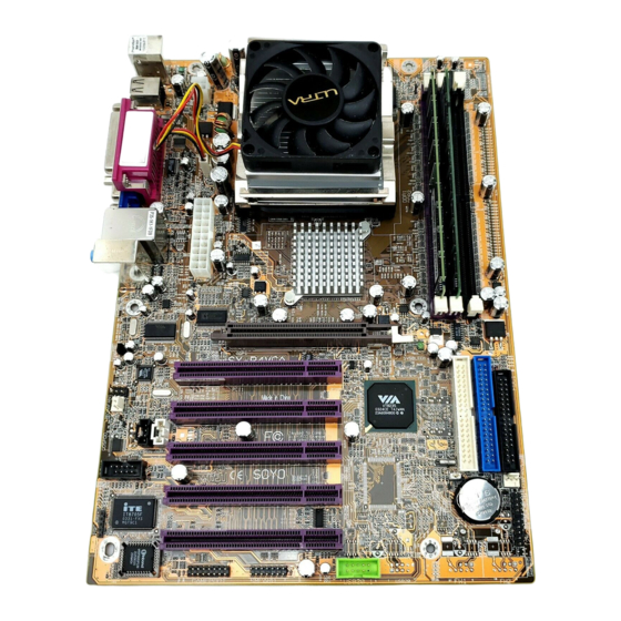
6.
On some mainboards, the actual chipset cooler may differ from
the chipset cooler as shown on the picture or on the box.
However, the chipset fan on the mainboard is of the same
quality and will work just as well as the one shown in the
picture. (The chipset cooler is as sufficient as the chipset fan
based on different design.)
7.
For immediate Technical questions, please visit SOYO tech
support link at
http://www.soyousa.com/kb.
http://www.soyousa.com/support
and
Advertisement
Table of Contents

Related Manuals for SOYO SY-P4VGA


Summary of Contents for SOYO SY-P4VGA
- Page 1 (The chipset cooler is as sufficient as the chipset fan based on different design.) For immediate Technical questions, please visit SOYO tech support link at http://www.soyousa.com/support...
- Page 2 SY-P4VGA Motherboard **************************************************** mPGA Socket 478 Processor supported VIA P4M266A AGP/PCI 533/400 MHz Front Side Bus supported ATX Form Factor **************************************************** User's Manual...
- Page 3 SY-P4VGA Copyright © 2003 by SOYO Computer Inc. Trademarks: SOYO is the registered trademark of SOYO Computer Inc. All trademarks are the properties of their owners. Product Rights: All names of the product and corporate mentioned in this publication are used for identification purposes only.
-
Page 4: Table Of Contents
CHAPTER 1 MOTHERBOARD DESCRIPTION......1 INTRODUCTION.............1 UNPACKING THE MOTHERBOARD ......1 KEY FEATURES..............2 HANDLING THE MOTHERBOARD ......5 ELECTROSTATIC DISCHARGE PRECAUTIONS..5 SY-P4VGA MOTHERBOARD LAYOUT .......6 SY-P4VGA MOTHERBOARD COMPONENTS ....7 CHAPTER 2 HARDWARE INSTALLATION ........9 PREPARATIONS..............9 INSTALLATION GUIDE ..........10 QUICK BIOS SETUP.............31 CHAPTER 3 BIOS SETUP UTILITY..........32 STANDARD CMOS SETUP..........35... -
Page 5: Chapter 1 Motherboard Description
Chapter 1 MOTHERBOARD DESCRIPTION 1-1 INTRODUCTION The SY-P4VGA AGP/PCI Motherboard is a high-performance Socket 478 processor supported ATX form-factor system board. The SY-P4VGA uses VIA Chipset technology and supports Socket 478 class processors. This Motherboard is fully compatible with industry standards and adds many technical enhancements. -
Page 6: Key Features
- Pentium® 4 With or without Hyperthreading, Northwood, Willamette (400/533 MHz FSB) - Pentium® 4 Celeron CPU SETTINGS The SY-P4VGA provides the user with a very complete and convenient CPU setting environment. EXPANDABILITY The SY-P4VGA provides all the standard expansion slots, and many more... -
Page 7: Hardware Monitor
The SY-P4VGA supports booting from devices such as CD-ROM. Power on by modem or alarm If the SY-P4VGA system is in suspend mode, it can be switched back on through the modem or RTC alarm through this function. This opens a lot of possibilities, such as remote access that switches the system on only after the modem receives a call. - Page 8 SOYO Bonus Pack CD-ROM A CDROM containing free bonus software. COMPLIANCE The SY-P4VGA complies with all important industry standards. The following underlines the reliability of the SY-P4VGA, a motherboard to trust. PC99, ACPI compliant USER FRIENDLY Jumperless design...
-
Page 9: Handling The Motherboard
Motherboard Description SY-P4VGA 1-4 HANDLING THE MOTHERBOARD To avoid damage to your Motherboard, follow these simple rules while unpacking: Before handling the Motherboard, ground yourself by grasping an unpainted portion of the system's metal chassis. Remove the Motherboard from its anti-static packaging. Hold the Motherboard by the edges and avoid touching its components. -
Page 10: Sy-P4Vga Motherboard Layout
Motherboard Description SY-P4VGA 1-6 SY-P4VGA MOTHERBOARD LAYOUT PS/2 Mouse PS/2 Mouse PS/2 KB Connector Connector DDR1 DDR2 SDR1 USB 1/USB 2 +12V Power COM A VGA out LAN Connector ATX Power USBLAN MIC IN / Center & Bass out Audio out / Front out... -
Page 11: Sy-P4Vga Motherboard Components
Motherboard Description SY-P4VGA 1-7 SY-P4VGA MOTHERBOARD COMPONENTS B C D... - Page 12 Motherboard Description SY-P4VGA ATX12V 4-Pin (+12V) Connector CPU Cooling Fan Connector (CPUFAN1,2) ATX Power Supply Connector 32-bit AGP Slot Socket 478 Connector VIA P4M266A North Bridge Chip DDR DIMM Banks SDRAM DIMM Bank 5V Stand-By Indicator LED Bus Mastering EIDE/ATAPI Ports...
-
Page 13: Chapter 2 Hardware Installation
Hardware Installation SY-P4VGA Chapter 2 HARDWARE INSTALLATION Congratulations on your purchase of SY-P4VGA Motherboard. You are about to install and connect your new Motherboard. Note: Do not unpack the Motherboard from its protective anti-static packaging until you have made the following preparations. -
Page 14: Installation Guide
Motherboard or system. BEGIN THE INSTALLATION STEP 1 Install the CPU To perform the installation of your new SY-P4VGA Motherboard, follow the steps below: ® CPU Mount Procedure: To mount the Pentium 4 Socket mPGA478 processor that you have purchased separately, follow these instructions. - Page 15 Hardware Installation SY-P4VGA Align the blunt edge of the CPU with the matching pinhole distinctive edge on the socket. Seat the processor in the socket completely and without forcing.
-
Page 16: Cpu Fan Installation
Hardware Installation SY-P4VGA Then close the socket handle to secure the CPU in place. Remember to connect the CPU Cooling Fan to the appropriate power connector on the Motherboard. The fan is a key component that will ensure system stability. The fan prevents overheating, therefore prolonging the life of your CPU. -
Page 17: Step 2 Install Memory Modules
Hardware Installation SY-P4VGA Step 2 Install Memory Modules DDR1 DDR2 SDR1 The P4VGA mainboard supports non ECC and non registered DDR and SDRAM modules. The largest possible memory size is 2GB when using DDR module or 1GB using SDRAM. Note1: Before installing or removing any memory modules system, power should be removed from the power supply (Remove AC cord from the power outlet). -
Page 18: Step 3 Install Expansion Cards
Hardware Installation SY-P4VGA Step 3 Install Expansion Cards The motherboard has 1 AGP slot and 5 PCI slot. Read the related expansion card’s instruction document before inserting the expansion card into the computer. Press the expansion card firmly into expansion slot in motherboard. - Page 19 Hardware Installation SY-P4VGA Step 4 Connect cables, case wires and power supply A. IDE Device Installation (HDD, CD-ROM) Pin -1 IDE 2 IDE 1 Secondary Primary This Motherboard offers two primary and secondary IDE device connectors (IDE1, IDE2). It can support up to four high-speed Ultra DMA 33/66/100/133 HDD or CD-ROM.
-
Page 20: Floppy Drive
Hardware Installation SY-P4VGA B. Floppy Drive Installation Pin -1 Floppy Drive Connector The system supports 5 possible floppy drive types: 720 KB, 1.2 MB, 1.44 MB, 2.88 MB, and LS-120. Connect one side of the 34-pin flat cable to the floppy drive and plug the other end to the floppy drive connector in the Motherboard. -
Page 21: Power Led
Hardware Installation SY-P4VGA Front Panel Connections HDD LED Speaker ACPI LED Key Lock PWRBT Power LED Reset Plug the computer case's front panel devices to the corresponding headers on the Motherboard. 1. Power LED Please install according to the following pin assignment: pin 1,3 are for Power LED. - Page 22 Hardware Installation SY-P4VGA 2. Reset Plug the Reset push-button cable into the 2-pin Reset header on the Motherboard. Pushing the Reset button on the front panel will cause the system to restart the boot-up sequence. Reset Pin Assignment Power Good 3.
- Page 23 Hardware Installation SY-P4VGA 5. ATX Power On/Off Switch Attach the 2-pin momentary type switch to the PWRBT header for turning On or Off your ATX power supply, so the 5V standby LED will always be lit. PWRBT Pin Assignment Power On/Off D.
- Page 24 Hardware Installation SY-P4VGA 1. Onboard Serial Ports COMA/COMB External peripherals that use serial transmission scheme include: serial mouse and modem. Plug the serial device cables directly into the COMA/COMB 9-pin male connectors located at the rear panel of the Motherboard.
- Page 25 Hardware Installation SY-P4VGA 5. Universal Serial Bus USB1/USB2,USB3/USB4,USB20_1 This Motherboard provides 6 USB2.0 ports for your additional devices. Plug the USB device jack into the available USB connector USB1, USB2, USB3 and USB4. USB20_1 is available. To make use of these USB ports, purchase a USB cable from your dealer.
- Page 26 Hardware Installation SY-P4VGA Line-in Line-out Mic-in E. Other Connections 1. Standard Infrared (SIRCON) Plug the 5-pin infrared device cable to the SIRCON header. This will enable the infrared transfer function. This Motherboard meets both the ASKIR and HPSIR specifications. Please install according to the following pin assignment:...
- Page 27 Hardware Installation SY-P4VGA 2. Cooling Fan Installation (1) CPU Cooling Fan (CPUFAN) After you have seated the CPU properly on the processor, attach the 3-pin fan cable to the CPUFAN connector on the Motherboard. The fan will stop when the system enters into Suspend Mode. (Suspend mode can be enabled from the BIOS Setup Utility, [POWER MANAGEMENT] menu.)
- Page 28 Hardware Installation SY-P4VGA (2) Chassis Cooling Fan (CHAFAN1,CHAFAN2) Some chassis also feature a cooling fan. This Motherboard features a CHAFAN connector to provide 12V power to the chassis fan. Connect the cable from the chassis fan to the CHAFAN 3-pin connector. Install...
-
Page 29: Pin Assignment
Hardware Installation SY-P4VGA 3. CD Line-in (CDIN) This Motherboard provides one CD Line-in connector. Please connect the 4-pin audio cable from your CD-ROM drive to CDIN. Please install according to the following pin assignment: CDIN (CD Line-in) Pin Assignment Left Right 5. - Page 30 Hardware Installation SY-P4VGA 4. Smart Card Reader 5. MIC & LED Connector (J30) MIC & LED Connector (J30) Pin Assignment Sound_R Sound_L LAN Action MIC IN You can connect the Line-out /MIC in/LAN LED to the front panel of your...
- Page 31 Hardware Installation SY-P4VGA 6. Serial Port COM2 In addition to the onboard serial connector COM2 located at the rear panel, your Motherboard comes with a second serial port COM2 equipped with a flat cable and external connector. The Motherboard package includes one serial port flat cable with a 9-pin connector.
- Page 32 Hardware Installation SY-P4VGA F. ATX12V Power Supply The power supply connector is the last connection to be made while installing a motherboard. This motherboard requires an ATX 12V power supply (For P4 system), an AT or ATX power supply cannot be used. We recommend a power supply of at least 350W, or 400W under full loading.
-
Page 33: Atx Power
Hardware Installation SY-P4VGA Note3: The minimum recommended wattage is 400W for a fully loaded system or 350W for a fully loaded system. The system might become unstable if power supply is not enough. Please install the ATX 12V power according to the following pin... -
Page 34: Step 5 Power On
Hardware Installation SY-P4VGA G. CMOS Clear (JP5) In some cases the CMOS memory may contain wrong data, follow the steps below to clear the CMOS memory. Clear the CMOS memory by momentarily shorting pin 2-3 on jumper JP5. This jumper can be easily identified by its white colored cap. -
Page 35: Quick Bios Setup
Hardware Installation SY-P4VGA 3. The BIOS Setup screen appears: Phoenix – Award BIOS CMOS Setup Utility Standard CMOS Features Load Fail - Safe Defaults Advanced BIOS Features Load Optimized Defaults Advanced Chipset Features Set Supervisor Password Integrated Peripherals Set User Password Power Management Setup Save &... -
Page 36: Chapter 3 Bios Setup Utility
BIOS Setup Utility SY-P4VGA Chapter 3 BIOS SETUP UTILITY This Motherboard's BIOS setup program uses the ROM PCI BIOS program from Award Software Inc. To enter the Award BIOS program's Main Menu: 1. Turn on or reboot the system. 2. After the diagnostic checks, press the [Del] key to enter the Award BIOS Setup Utility. - Page 37 BIOS Setup Utility SY-P4VGA Hot Keys: Function keys give you access to a group of commands throughout the BIOS utility. Function Command Description Gives the list of options available for each General Help item. Previous Restore the old values. These are the values Values that the user started the current session with.
-
Page 38: Save And Exit Setup
BIOS Setup Utility SY-P4VGA SAVE AND EXIT SETUP Select the [SAVE & EXIT SETUP] option from the Main Menu to save data to CMOS and exit the setup utility. This option saves all your changes and causes the system to reboot. -
Page 39: Standard Cmos Setup
BIOS Setup Utility SY-P4VGA STANDARD CMOS SETUP Select the [STANDARD CMOS SETUP] option from the Main Menu and press [Enter] key. Phoenix – Award BIOS CMOS Setup Utility Standard CMOS Features Date (mm:dd:yy) Mon, Jan 1 2001 Item Help Time (hh:mm:ss) - Page 40 BIOS Setup Utility SY-P4VGA This Main Menu function automatically detects the hard disk type and configures the [Standard CMOS Features] accordingly. Phoenix – Award BIOS CMOS Setup Utility IDE Primary Master IDE HDD Auto-Detection Press Enter Item Help IDE Primary Master...
-
Page 41: Floppy Drives
BIOS Setup Utility SY-P4VGA Hard Disks Type & Mode Choose the type and mode for the hard disks that you have already installed. Setting Description Note IDE HDD Press To auto-detect the HDD’s Enter cylinders, head, sectors and size on... - Page 42 BIOS Setup Utility SY-P4VGA Others Optional Setting Description Note EGA/VGA Select the video mode, Default Video supported by your VGA card CGA 40 and memory. CGA 80 MONO (Monochrome) ALL Errors When the BIOS detects system Default Halt On errors, this function will stop the No Errors system.
-
Page 43: Advanced Bios Features
BIOS Setup Utility SY-P4VGA 3-2 ADVANCED BIOS FEATURES Select the [Advanced BIOS Features] option from the Main Menu and press [Enter] key. Phoenix – Award BIOS CMOS Setup Utility Advanced BIOS Features Virus Warning Disabled Item Help CPU L1 & L2 Cache... -
Page 44: Quick Power On Self Test
BIOS Setup Utility SY-P4VGA Cache Memory Options Setting Description Note Disabled Because the CPU is faster than CPU L1 & L2 Cache memory, the CPU after has to Enabled Default wait to complete memory access. By enabling L2 caching you will let the CPU write or... -
Page 45: Typematic Settings
BIOS Setup Utility SY-P4VGA System Boot Control Settings (Continue) Setting Description Note Disabled Selects if the system should try to Boot Other Device find any other bootable devices. Enabled Default If the first, second and third boot device cannot be booted from. -
Page 46: Security Option
BIOS Setup Utility SY-P4VGA Typematic Settings (Continue) Setting Description Note 250 (msec) Choose how long after Default Typematic Delay you press a key down the 500 (msec) character begins 750 (msec) repeating. 1000 (msec) Security Option Use this feature to prevent unauthorized system boot-up or use of BIOS Setup. - Page 47 ROM to RAM. BIOS shadow copies BIOS code from slower ROM to faster RAM. BIOS can then execute from RAM. EPA LOGO LOGO-0 Allows user to display SOYO logo Default SELECT or own logo. LOGO-1 Logo-0 Shows SOYO logo.
-
Page 48: Advanced Chipset Features
BIOS Setup Utility SY-P4VGA 3-3 ADVANCED CHIPSET FEATURES Select the [Advanced Chipset Features] option from the Main Menu and press [Enter] key. Caution: Change these settings only if you are already familiar with the Chipset. The [Advanced Chipset Features] option changes the values of the chipset registers. - Page 49 BIOS Setup Utility SY-P4VGA CHIPSET FEATURES SETUP (Continue) Setting Description Note VGA Share Disabled The amount of main memory that is Memory Size reserved for use by the inboard VGA. This part of the system memory is not available for use by Default programs.
- Page 50 BIOS Setup Utility SY-P4VGA 3-3.1 DRAM Clock/Drive Control Caution: Change these settings only if you are already familiar with the Chipset. The [DRAM Clock/Drive Control] option changes the values of the chipset registers. These registers control the system options in the computer.
- Page 51 BIOS Setup Utility SY-P4VGA DRAM Control Setting Description Note DRAM Clock By SPD This item allows you to control Default the DRAM clock speed. Manual DRAM Timing By SPD If enable the DRAM will auto Default detect the DRAM timing.
- Page 52 BIOS Setup Utility SY-P4VGA 3-3.2 AGP & P2P Bridge Control Caution: Change these settings only if you are already familiar with the Chipset. The [AGP & P2P Bridge Control] option changes the values of the chipset registers. These registers control the system options in the computer.
- Page 53 BIOS Setup Utility SY-P4VGA AGP & P2P Bridge Control (Continue) Setting Description Note AGP Driving Auto This item allows you to adjust the AGP Default driving force. Choose Manual to key Control Manual in a AGP Driving Value in the next selection.
- Page 54 BIOS Setup Utility SY-P4VGA 3-3.3 CPU & PCI Bus Control Caution: Change these settings only if you are already familiar with the Chipset. The [CPU & PCI Bus Control] option changes the values of the chipset registers. These registers control the system options in the computer.
-
Page 55: Integrated Peripherals
BIOS Setup Utility SY-P4VGA 3-4 INTEGRATED PERIPHERALS Select the [Integrated Peripherals] option from the Main Menu and press [Enter] key. Caution: Change these settings only if you are already familiar with the Chipset. The [INTEGRATED PERIPHERALS] option changes the values of the chipset registers. - Page 56 BIOS Setup Utility SY-P4VGA INTEGRATED PERIPHERALS Setting Description Note OnChip USB All Disabled This should be enabled if your system has a USB Controller All Enabled Default installed on the system 1&2 USB Port board and you want to use 1 USB Port it.
-
Page 57: Via Onchip Ide Device
BIOS Setup Utility SY-P4VGA 3-4.1 VIA OnChip IDE Device Caution: Change these settings only if you are already familiar with the Chipset. The [VIA OnChip IDE Device] option changes the values of the chipset registers. These registers control the system options in the computer. - Page 58 BIOS Setup Utility SY-P4VGA VIA OnChip IDE Device Setting Description Note Disabled Turn off the on-board IDE. On-Chip PCI IDE Primary Enabled Use the on-board IDE. Default Secondary mode 0-4 0 is the slowest speed Primary Master PIO 4 is the fastest speed...
-
Page 59: Via Onchip Pci Device
BIOS Setup Utility SY-P4VGA 3-4.2 VIA OnChip PCI Device Caution: Change these settings only if you are already familiar with the Chipset. The [VIA OnChip PCI Device] option changes the values of the chipset registers. These registers control the system options in the computer. -
Page 60: Superio Device
BIOS Setup Utility SY-P4VGA 3-4.3 SuperIO Device Caution: Change these settings only if you are already familiar with the Chipset. The [SuperIO Device] option changes the values of the chipset registers. These registers control the system options in the computer. - Page 61 BIOS Setup Utility SY-P4VGA SuperIO Device (Continue) Setting Description Note UART Mode IrDA The second serial port offers several special modes. It can ASKIR work as an infrared device (IrDA, Normal Default ASKIR) as a smart card reader (SCR), or as a normal serial port.
-
Page 62: Power Management Setup
BIOS Setup Utility SY-P4VGA 3-5 POWER MANAGEMENT SETUP The [POWER MANAGEMENT SETUP] sets the system's power saving functions. Phoenix – Award BIOS CMOS Setup Utility Power Management Setup Item Help ACPI Suspend Type S1 (POS) Power Management Option User Define... - Page 63 BIOS Setup Utility SY-P4VGA Power Management Controls Setting Description Note ACPI Suspend S1(POS) The system will enter the S1 Default Type state during suspend. (Low S3(STR) latency wake up) S1 & S3 Power User Define Lets you define the system...
- Page 64 BIOS Setup Utility SY-P4VGA Power Management Controls (Continue) Setting Description Note MODEM Use Selects which IRQ the modem Default uses to wake up from. 4-11, NA Soft-Off by Instant-off Default PWR-BTTN Delay 4 Sec. Turns off the system power 4 seconds after pushing the power button.
- Page 65 BIOS Setup Utility SY-P4VGA IRQ/Event Activity Detect Setting Description Note When On of VGA, any activity from one of the listed system Default peripheral devices or IRQs wakes up the system. LPT & COM LPT/COM When On of LPT & COM, any...
-
Page 66: Irqs Activity Monitoring
BIOS Setup Utility SY-P4VGA 3-5.1 IRQs Activity Monitoring This option sets the IRQs Activity Monitoring. Phoenix – Award BIOS CMOS Setup Utility IRQs Activity Monitoring Primary INTR Item Help IRQ3 (COM 2) Disabled IRQ4 (COM 1) Enabled Menu Level IRQ5 (LPT 2) -
Page 67: Pnp/Pci Configurations
BIOS Setup Utility SY-P4VGA 3-6 PNP/PCI CONFIGURATIONS This option sets the Motherboard’s PCI Slots. Phoenix – Award BIOS CMOS Setup Utility PNP/PCI Configurations PNP OS Installed Item Help Reset Configuration Data Disabled Menu Level Resources Controlled By Auto (ESCD) Select Yes if you are using a... -
Page 68: Pnp/Pci Configuration Controls
BIOS Setup Utility SY-P4VGA PNP/PCI Configuration Controls Setting Description Note Set this field to [Yes] if you PNP OS Installed are running Windows 95, which is PnP compatible. If the OS you are running Default does not support PnP (If there is any doubt, set this configuration. - Page 69 BIOS Setup Utility SY-P4VGA PNP/PCI Configuration Setup (Continue) Setting Description Note Interrupt How to set the BIOS to release the IRQ to the PnP Interrupt pool: Line PnP / PCI configuration Integrated Peripherals IRQ 15 IRQ 15: PCI / ISA PnP On-Chip Secondary PCI IDE: disabled...
-
Page 70: Pc Health Status
BIOS Setup Utility SY-P4VGA 3-7 PC HEALTH STATUS This option shows the Motherboard's PC Health Status. Phoenix – Award BIOS CMOS Setup Utility PC Health Status CPU Vcore 1.44V Item Help 3.3 V 3.22 V + 5 V 5.05 V... -
Page 71: Load Fail-Safe Defaults
BIOS Setup Utility SY-P4VGA 3-8 LOAD FAIL-SAFE DEFAULTS Select the [Load Fail-Safe Defaults] option from the Main Menu to load a pre-defined safe BIOS settings. This option is recommended if you have instability issues. Phoenix – Award BIOS CMOS Setup Utility... -
Page 72: Load Optimized Defaults
BIOS Setup Utility SY-P4VGA 3-9 LOAD OPTIMIZED DEFAULTS Select the [Load Optimized Defaults] option from the Main Menu to load the pre-defined optimized BIOS settings. Phoenix – Award BIOS CMOS Setup Utility Standard CMOS Features Load Fail - Safe Defaults... -
Page 73: Set Supervisor Password
BIOS Setup Utility SY-P4VGA 3-10 SET SUPERVISOR PASSWORD Based on the setting you have made in the [Security Option] of the [BIOS FEATURES SETUP] section, the password prevents access to the system or the setup program by unauthorized users. Follow this procedure to set a... -
Page 74: Set User Password
BIOS Setup Utility SY-P4VGA Enter your new password and press [Enter]. The following message appears, prompting to confirm the new password: Confirm Password: Re-enter your password and then press [Enter] to exit to the Main Menu. This diagram outlines the password selection procedure: Type the Password Press <Enter>... -
Page 75: Boot Menu
BIOS Setup Utility SY-P4VGA BOOT MENU Boot Menu enables user to boot-up on different boot device without going into the BIOS setup. To enable boot Menu, press “ESC” after memory and option ROM initialization. The user will see a device menu, in which he or she can choose from which device they wish to boot. -
Page 76: Cahpter 4 Drivers Installation
Step 1. Insert the SOYO CD into the CD-ROM drive If you are running Windows NT, 2K or XP, the SOYO-CD will not detect your motherboard type. In that case the following dialog will pop up. Please choose your motherboard model number and press OK. - Page 77 SOYO Motherboard you own and displays the corresponding model name. The user's manual files included on the SOYO CD are in PDF (Postscript Document) format. In order to read a PDF file, the appropriate Acrobat Reader software must be installed on your system.
- Page 78 Drivers Installation SY-P4VGA Step 2. Install Drivers and Utilities Click the Install Drivers button to display the list of drivers software that can be installed with your Motherboard. The Start Up program displays the drivers available for the particular model of Motherboard you own. We recommend that you only install those drivers.
- Page 79 Drivers Installation SY-P4VGA AGP VxD Driver VIA AGP VxD Driver is to be installed if you are using an AGP VGA device. VIAGART.VXD will provide service routines to your VGA driver and interface directly to hardware, providing fast graphical access.
- Page 80 Step 3. Check the Latest Releases Click the 'Connect to SOYO website' button to go the SOYO Website to find the latest BIOS, manual and driver releases for your motherboard. This button will only work if your computer is connected to the internet through a network or modem connection.
- Page 81 Drivers Installation SY-P4VGA After Windows XP installation, your device manager should look like this:...
- Page 82 Drivers Installation SY-P4VGA After driver installation, your Windows XP device manager should look like this: Note: To install the USB 2.0 driver, please update to Windows XP service pack 1.
- Page 83 Drivers Installation SY-P4VGA Directory list of the driver CD VIA audio driver VIA audio software VIA 4 in 1 driver VIA LAN driver VIA USB2.0 driver (not for Windows XP) VIA onboard display driver...
-
Page 84: Chapter 5 Via Usb2.0 Driver Installation
VIA USB2.0 Driver Installation SY-P4VGA Chapter 5 VIA USB2.0 Driver Installation Installing the VIA LAN Drivers under Windows XP USB 2.0 Drivers are available for download using Windows Update for both Windows XP. Alternatively, installing service pack 1 will also install the USB 2.0 drivers. -
Page 85: Appendix A Troubleshooting At First Start
APPENDIX A Troubleshooting at First Start Boot-up Issues The system does not power-up, no beeping sound heard and the CPU fan does not turn on. Check if the power cord is plug to the power source. Check if the power is connected to the M/B. Check if the cable of the case power button is connected to the M/B power button connector (see connectors and plug-ins in the manual for more info). - Page 86 The system power-up, no video, beeping heard. Clear CMOS battery. (JP5 connector, see the Quick start guide for more info on how to clear the CMOS). Check if the memory module and the VGA card are inserted properly in the M/B. If yes, change the memory module, it might be defective.
-
Page 87: Stability Issues
Make sure the boot device (Harddisk, CDROM, Floppy, etc…) you are trying to boot from contains a valid, bootable medium or is bootable. During Boot-up, my computer says CMOS memory Checksum error. What is the problem? Clear CMOS memory. Redo your CMOS setup settings. If your battery is empty, the error will occur more frequently. - Page 88 2AA2 BIOS. Where can I find the latest BIOS for my motherboard? Please go to the technical support page of one of the SOYO websites (Taiwan: www.soyo.com.tw; USA: http://www.soyousa.com/), and look up your motherboard to find the latest BIOS revision.
-
Page 89: Vga Issue
Try clearing the CMOS RAM. The BIOS chip is defective due to an unsuccessful flash, contact your nearest SOYO branch for re-flashing. Is there a way to reprogram my BIOS after an unsuccessful flash? There is no other way, you need to send back the BIOS ROM to your nearest SOYO branch for re-flashing. - Page 90 3. Install the audio driver supplied on our driver disc. 4. Check BIOS setup if “AC97 Audio” is enabled. If sound already installed, check our website for an audio driver update. The sound is working in my system, but when I play CD music from the CD-ROM, I do not get any sound.
- Page 91 LAN Issues During LAN driver installation, the system hangs on 75%, why? Enable the onboard LAN in the BIOS setup. I have problems installing Novell NetWare v.50 Disable the APIC option in the BIOS. For updated FAQs, please check http://www.soyo.com.tw/faq.htm http://www.soyousa.com/faqs.html...
-
Page 92: Appendix B Contact Information
APPENDIX B How to contact us: If you are interested in our products, please contact the SOYO sales department in the region you live. If you require Technical Assistance, please contact our Technical Support in the region you live. SOYO prefers Email as communication medium, remember to always add to the email the country that you live in.