Nordyne R-410A Installation And User Manual
16 seer two stage r-410a split system
Hide thumbs
Also See for R-410A:
- Installation instructions manual (25 pages) ,
- User's manual & installation instructions (20 pages) ,
- User manual and installation instructions (20 pages)
Table of Contents
Advertisement
AIR CONDITIONER
User's Manual / Installation Instructions
Two Stage R-410A Split System
Please read this information thoroughly and become familiar with the
capabilities and use of your appliance before attempting to operate or
maintain this unit. Keep this literature where you have easy access to
it in the future. If a problem occurs, check the instructions and follow
recommendations given. If these suggestions don't eliminate your
problem, call your servicing contractor .
These instructions are primarily intended to assist qualifi ed individuals
experienced in the proper installation of this appliance. Some local
codes require licensed installation/service personnel for this type of
equipment. Please read all instructions carefully before starting the
installation.
DO NOT DESTROY. PLEASE READ CAREFULLY AND
KEEP IN A SAFE PLACE FOR FUTURE REFERENCE.
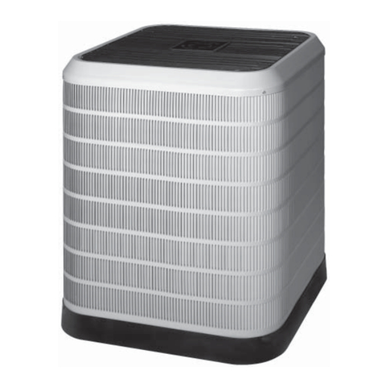
Premium Model Shown
IMPORTANT
16 SEER
Advertisement
Table of Contents

Related Manuals for Nordyne R-410A


Summary of Contents for Nordyne R-410A
- Page 1 AIR CONDITIONER 16 SEER User’s Manual / Installation Instructions Two Stage R-410A Split System Premium Model Shown IMPORTANT Please read this information thoroughly and become familiar with the capabilities and use of your appliance before attempting to operate or maintain this unit. Keep this literature where you have easy access to it in the future.
-
Page 3: Table Of Contents
Slab Mount ..........7 Adjustment of Refrigerant Charge ....12 Cantilever Mount ........7 Roof Mount ..........8 Charging R-410A Unit in AC Mode ..13 Connecting Refrigerant Tubing Between Cooling Charging Charts ......13 the Indoor and Outdoor Unit ....... 8 Troubleshooting Tables ......16 General Information ........ -
Page 4: Safety Information
USER INFORMATION OPERATING INSTRUCTIONS SAFETY INFORMATION Please refer to the thermostat manufacturer’s IMPORTANT: Safety markings are used User Manual for detailed programming frequently throughout this manual to designate instructions. a degree or level of seriousness and should not be ignored. WARNING indicates a potentially For this type of equipment to function as intended, hazardous situation that if not avoided, could a two stage cooling / heating thermostat is... -
Page 5: Warranty Information
USER INFORMATION Operating the Indoor Blower Continuously SYSTEM MAINTENANCE The continuous indoor blower operation is typically used to circulate the indoor air to CAUTION: equalize a temperature unbalance due to a sun load, cooking, or fi replace operation. Shut off all electrical power to the unit Set the thermostat fan mode to ON (Figure 1). -
Page 6: Brazing Operations
These units are fully charged with • All electrical wiring must be completed in R-410A refrigerant and ready for accordance with local, state and national installation. When a system is installed codes and regulations and with the National... -
Page 7: General Information
GENERAL INFORMATION SITE PREPARATION Split System units are designed for use with a wide Unpacking the Equipment variety of fossil fuel furnaces, electric furnaces, Remove the shipping carton and User’s Manual air handlers, and evaporator coil combinations from the equipment. Take care not to damage the equipped with variable speed blowers. -
Page 8: Roof Mount
BETWEEN THE INDOOR & OUTDOOR UNIT manufacturer’s installation instructions. ELECTRICAL CONNECTIONS CAUTION: WARNING: This system uses R-410A refrigerant with POE oil. When servicing, cover or Shut off all electrical power to the unit seal openings to minimize the exposure before performing any maintenance or... -
Page 9: Outdoor Unit Connections
• Connect the line-voltage leads to the COPPER WIRE SIZE — AWG terminals on the contactor inside the control (1% Voltage Drop) compartment. Supply Wire Length-Feet Supply Circuit • Use only copper wire for the line voltage power Ampacity supply to this unit (Table 1). Use proper code agency listed conduit and a conduit connector for connecting the supply wires to the unit. -
Page 10: Vac Power Wiring
Comfort Alert Diagnostics Module VAC. When the coil is not energized, the demand The Comfort Alert diagnostics module is a signal input should be less than 0.5 VAC. breakthrough innovation for troubleshooting air NOTES: conditioning system failures. The module installs •... -
Page 11: Optional Equipment
Optional Equipment FUNCTIONAL CHECKOUTS Optional equipment requiring connection to the power or control circuits must be wired in CAUTION: strict accordance with current provisions of the NEC (ANSI/NFPA 70), with applicable local These units have a crankcase heater codes having jurisdiction, and the installation factory installed. -
Page 12: Short Cycle Protection
Table 3. Split System in accordance with the checkout procedures Air Conditioner Charge supplied with the equipment. Charging an R-410A unit in AC mode at ADJUSTMENT OF REFRIGERANT outdoor temperatures above 65F. CHARGE: 1. With the system operating at steady-state,... -
Page 13: Cooling Charging Charts
Cooling Charging Charts *4BF-024KA Charging Chart Remove refrigerant when above curve Add refrigerant when below curve Liquid Temperature (F) Figure 4. Charging Chart for 2 Ton Units *4BF-036KA Charging Chart Remove refrigerant when above curve Remove refrigerant when above curve Add refrigerant when below curve Liquid Temperature (F) Figure 5. - Page 14 Cooling Charging Charts (continued) *4BF-048KB Charging Chart Remove refrigerant when above curve Liquid Temperature (F) Figure 6. Charging Chart for 4 Ton Units *4BF-060KB Charging Chart Remove refrigerant when above curve Add no more than 0.5 lbs refrigerant when between curve and saturation line. If assistance is needed, call 1-800-4AC-HEAT Liquid Temperature (F) Figure 7.
- Page 15 TROUBLESHOOTING Status Status LED Status LED Troubleshooting Information Description Green Module has Supply voltage is present at module terminals “POWER” power • Compressor protector is open • Check for high head pressure Thermostat • Check compressor supply voltage demand signal •...
- Page 16 TROUBLESHOOTING - CONTINUED Status LED Status LED Status LED Troubleshooting Information Description • Thermostat demand signal is intermittent Short Cycling • Yellow “ALERT” Compressor is Low line voltage (contact utility if voltage at disconnect is low) Flash Code 3 running only •...
- Page 17 TROUBLESHOOTING - CONTINUED Miswired Module Indication Recommended Troubleshooting Action Green LED is not on, module • Determine if both R & C module terminals are connected. does not power up • Verify voltage is present at module’s R & C terminals. Green intermittent, •...
- Page 20 INSTALLER: PLEASE LEAVE THESE INSTALLATION INSTRUCTIONS WITH THE HOMEOWNER. ¢709129;¤ 7091290(Replaces 7090240) Specifi cations and illustrations subject to change without notice or incurring obligations. O’Fallon, MO 7091290 Printed in U.S.A. (11/09)