Nordyne R-410A User's Manual & Installation Instructions
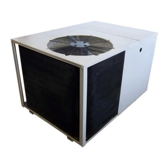
Single package heat pump - 2 stage, r-410a
Hide thumbs
Also See for R-410A:
- Installation instructions manual (25 pages) ,
- User's manual & installation instructions (20 pages) ,
- User manual and installation instructions (20 pages)
Table of Contents
Advertisement
Q5RF SERIES
USER's MANUAL & INSTALLATION INSTRUCTIONS
Single Package Heat Pump - 2 Stage, R-410A
Please read this information thoroughly and become familiar with the capabilities
and use of your appliance before attempting to operate or maintain this unit.
Keep this literature where you have easy access to it in the future. If a problem
occurs, check the instructions and follow recommendations given. If these
suggestions don't eliminate your problem, call your Servicing Contractor.
These instructions are primarily intended to assist qualifi ed individuals
experienced in the proper installation of this appliance. Some local codes
require licensed installation/service personnel for this type of equipment.
Please read all instructions carefully before starting the installation.
DO NOT DESTROY. PLEASE READ CAREFULLY AND
KEEP IN A SAFE PLACE FOR FUTURE REFERENCE.
IMPORTANT
15 SEER
Advertisement
Table of Contents

Related Manuals for Nordyne R-410A


Summary of Contents for Nordyne R-410A
- Page 1 Q5RF SERIES 15 SEER USER’s MANUAL & INSTALLATION INSTRUCTIONS Single Package Heat Pump - 2 Stage, R-410A IMPORTANT Please read this information thoroughly and become familiar with the capabilities and use of your appliance before attempting to operate or maintain this unit. Keep this literature where you have easy access to it in the future.
-
Page 2: Table Of Contents
Forced Defrost Mode (Field Test) .....12 USER INFORMATION Anti Short Cycle Timer Test ......12 About the Heat Pump ........3 Heating Mode ........12 Cooling Mode .........13 Operating Instructions ........ 3 Cooling Operation ........3 Adjustment of Refrigerant Charge ....13 Heating Operation ........3 Charging an R410A Unit in AC Emergency Heat ........ -
Page 3: User Information
USER INFORMATION ABOUT THE HEAT PUMP minutes following a previous operation or the interruption of the main electrical power. Your heat pump is a unique, all weather comfort- control appliance that will heat and cool your Emergency Heat home year round and provide energy saving Some thermostats may include a system mode comfort. -
Page 4: Installer Information
INSTALLER INFORMATION GENERAL INFORMATION SAFETY INFORMATION Single packaged heat pumps are ready for easy and immediate installation and can be readily WARNING: connected into the high static duct system of a home. This unit is completely assembled, wired, The information listed below and run tested at the factory. -
Page 5: Air Duct System
Air Duct System Air ducts must be installed in accordance with the standards of the National Fire Protection Elbow Association “Standard for Installation of Air Conditioning and Ventilation Systems” (NFPA 90A), “Standard for Installation of Residence Type Warm Air Heating and Air Conditioning Systems” (NFPA 90B), these instructions, and all applicable codes. -
Page 6: Installing Return & Supply Air Fittings
12" 12" 24" 0" Supply Air Return Air Figure 3. Minimum Unit Clearances Figure 4. Return and Supply Air Fittings Installing Return & Supply Air Fittings The supply and return fi ttings are included with 2. Overlap the collar ends keeping the small the unit and located in the supply duct. -
Page 7: Locating & Installing The Supply Dampers
NOTE: The return air box with grille and fi lter Locating & Installing the Supply Damper(s) (Figure 6) should not be located in heavy traffi c When locating the supply damper(s), carefully areas like hallways or center of rooms. A good check fl... -
Page 8: Electrical Connections
ELECTRICAL CONNECTIONS • See the unit wiring label for proper high and low voltage wiring. Make all electrical connections in accordance with all applicable codes and WARNING: ordinances. To avoid electric shock, personal CAUTION: injury, or death, turn off the electric power at the disconnect or the main L a b e l a l l... -
Page 9: Overcurrent Protection
Overcurrent Protection Overcurrent protection must be provided at the CAUTION: branch circuit distribution panel and sized as shown on the unit rating label and according to To avoid personal injury or applicable local codes. Generally, the best fuse property damage, make certain or breaker for any heat pump is the smallest that the motor leads cannot size that will permit the equipment to run under... - Page 10 Demand Defrost Control Electric Heat Package (optional) The demand defrost board controls the defrost This heat pump is shipped without an auxiliary cycle in response to ambient temperature, electric heat kit installed. If electric heat is desired, outdoor coil temperature and accumulated an accessory Heater Kit must be fi...
-
Page 11: Demand Defrost Control
Outdoor Thermostat Y1 = 1st Stage Heat Pump (optional) Y2 = 2nd Stage Heat Pump W1 = 1st Stage Auxillary Heat Green (from blower relay) Accessory Heat Plug Brown Orange Blower Relay Compressor Solenoid Demand Defrost Board ECM Motor (if applicable) Typical Wiring (Field Supplied) for 2-Stage Cool, 1 Stage Electric Heat Y1 = 1st Stage Heat Pump Y2 = 2nd Stage Heat Pump... -
Page 12: Startup & Adjustments
STARTUP & ADJUSTMENTS temperature selector below the existing room temperature. Allow the cooling system to operate Pre-Start Checklist for several minutes and check for the discharge The following check list should be observed prior of cool air at the supply registers. to starting the unit. -
Page 13: Cooling Mode
Cooling Mode Charging an R-410A Unit in Heating Mode When the TEST pins are shorted together for 1. E va c u a t e t h e r e f r i g e r a n t s y s t e m . more than 1 second, the Anti Short Cycle Timer 2. -
Page 14: Refrigerant Charging Charts For Cooling Mode Of Operation
Refrigerant Charging Charts for Cooling Mode of Operation Q5RF-X24K CHARGING CHART R em ove refrigerant w hen above c urve Add refrigerant w hen below c urve LIQUID TEMPERATURE (F) Figure 11. Charging Chart for 2 ton Units Q5RF-X36K CHARGING CHART R em ove refrigerant w hen above c urve Add refrigerant w hen below c urve LIQUID TEMPERATURE (F) - Page 15 Refrigerant Charging Charts for Cooling Mode of Operation - Continued Q5RF-X48K CHARGING CHART R em ove refrigerant w hen above c urve Add refrigerant w hen below c urve LIQUID TEMPERATURE (F) Figure 13. Charging Chart for 4 ton Units Q5RF-X60K COOLING CHARGING CHART R em ove refrigerant w hen above c urve Add refrigerant w hen below c urve...
-
Page 18: Wiring Diagrams
YELLOW YELLOW BLACK YELLOW BLUE THERMISTOR THERMISTOR AMBIENT COIL FUSE Figure 15. Q5RF/PPH2RF Series Wiring Diagram - 2 & 3 Ton Units... - Page 19 YELLOW BLACK YELLOW BLUE BLUE THERMISTOR THERMISTOR AMBIENT COIL FUSE Figure 16. Q5RF/PPH2RF Series Wiring Diagram - 4 & 5 Ton Units...
-
Page 20: Component Functions
COMPONENT FUNCTIONS High Pressure Switch The high pressure switch is factory installed Low Pressure Switch and located in the compressor discharge line The low pressure switch is factory installed and internal to the unit. The switch is designed to de- located in the suction line internal to the unit.