Table of Contents
Advertisement
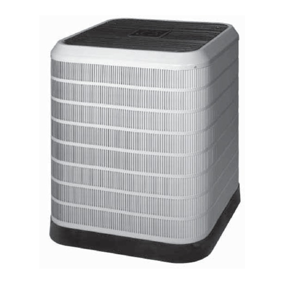
AiR CONDiTiONER
16 SEER
Two Stage R-410A Split System
Premium Model Shown
Please read this information thoroughly
and become familiar with the
capabilities
and use of your appliance
before attempting
to operate or
maintain this unit. Keep this literature where you have easy access to
it in the future. If a problem occurs, check the instructions and follow
recommendations
given. If these
suggestions
don't eliminate
your
problem, call your servicing
contractor.
These instructions are primarily intended to assist qualified individuals
experienced
in the proper installation of this appliance.
Some local
codes require licensed
installation/service
personnel
for this type of
equipment.
Please read all instructions
carefully
before starting
the
installation.
Advertisement
Table of Contents

Related Manuals for Nordyne 16 SEER


Summary of Contents for Nordyne 16 SEER
- Page 1 AiR CONDiTiONER 16 SEER Two Stage R-410A Split System Premium Model Shown Please read this information thoroughly and become familiar with the capabilities and use of your appliance before attempting to operate or maintain this unit. Keep this literature where you have easy access to it in the future.
-
Page 3: Table Of Contents
Safety information ........Oper. the Indoor Blower Continuously ..5 About the Air Conditioner ......Shutting the AC Off ........What are the Benefits of a Split Warranty information ........System? ............System Maintenance ........What are the Benefits of Two - Stage Regular Cleaning ........ -
Page 4: Safety Information
OPERATING INSTRUCTIONS SAFETY INFORMATION Please refer to the thermostat manufacturer's IMPORTANT: Safety markings used User Manual detailed programming frequently throughout this manual to designate instructions. a degree or level of seriousness and should not be ignored. WARNING indicates a potentially For this type of equipment to function as intended, hazardous situation... -
Page 5: Oper. The Indoor Blower Continuously
Operatingthe indoor BlowerContinuously SYSTEM MAINTENANCE The continuous indoor blower operation typically used to circulate the indoor air to CAUTION'. equalize a temperature unbalance due to a sun load, cooking, or fireplace operation. Shut off all electrical power to the unit Set the thermostat fan mode to ON (Figure 1). -
Page 6: Safety Information
SAFETY INFORMATION IMPORTANT: Safety markings used frequently throughout this manual to designate a degree or level of seriousness and should not be ignored. WARNING indicates a potentially The safety information listed below hazardous situation that if not avoided, could must be followed during the installation, result in personal injury or death. -
Page 7: General Information
GENERAL INFORMATION SITE PREPARATION Split System units are designed for use with a wide Unpacking the Equipment variety of fossil fuel furnaces, electric furnaces, Remove the shipping carton and User's Manual air handlers, and evaporator coil combinations from the equipment. Take care not to damage the equipped with variable speed blowers. -
Page 8: Roof Mount
Roof Mount The maximum recommended interconnecting refrigerant line length is 75 feet, and the vertical elevation difference between the indoor and WARNING: outdoor sections should not exceed 20 feet. If precise forming of refrigerant lines To avoid the risk of property damage, is required, a copper... -
Page 9: Outdoor Unit Connections
, Connect the line-voltage leads to the COPPER WIRE SIZE -- AWG terminals on thecontactor i nsidethecontrol (1% Voltage Drop) compartment. Supply Wire Length=Feet Supply Circuit Use only copper wire for the line voltage power Ampacity supply to this unit (Table 1). Use proper code agency listed conduit and a conduit connector for connecting the supply wires to the unit. -
Page 10: Comfort Alert
Comfort Alert Diagnostics Module VAC.When the coil is not energized, the demand The Comfort Alert diagnostics module is a signal input should be less than 0.5 VAC. breakthrough innovation for troubleshooting NOTES: conditioning system failures.The module installs Factory installed modules have different easily in the electrical... -
Page 11: Two - Speed Outdoor Fan Motor
OptionalEquipment FUNCTIONAL CHECKOUTS Optionalequipmentrequiringconnectionto the poweror controlcircuitsmustbe wiredin CAUTION: strictaccordance w ithcurrentprovisions o f the NEC (ANSl/NFPA 70), with applicablelocal These units have a crankcase heater codeshavingjurisdiction, a nd the installation factory installed. Wait 24 hours prior to instructions provided with the equipment. performing a function checkout... -
Page 12: Short Cycleprotection
Short CycleProtection not recommended and deviatons from rated 1. Withthesystem operating i nCOOLING mode, airflows or non-listed equipment combinations record thesetpoint t emperature s ettingofthe may requiree modifications to the expansion thermostat. devices and refrigerant charging procedures 2. Graduallyraise the setpointtemperature for proper and eficient system... -
Page 13: Charging R-410A Unit In Ac Mode
Cooling Charging Charts *4BF-024KA Charging Chart 575i___R_emove refrigerant when above curve 55oi 525! soo! 4751 450! 42si 4001 3751 350! o" 325! 300! 2751 250! ..// 225 i _Add refrigerant when below curve_ 200 i Liquid Temperature Figure 4. Charging Chart for 2 Ton Units *4BF-036KA Charging Chart... - Page 14 Cooling Charging Charts (continued) *4BF-048KB Charging Chart 575 _ Remove refrigerant when above curve /,,/,-/ -_'e 425 8 400 "5 /> Add refrigerant when below curve_ Liquid Temperature (F) Figure 6. Charging Chart for 4Ton Units *4BF-060KB Charging Chart "o "5 o"...
- Page 15 TROUBLESHOOTING Status Status LED Status LED Troubleshooting information Description Green Module has Supply voltage is present at module terminals "POWER" power , Compressor protector is open , Check for high head pressure Thermostat ,, Check compressor supply voltage demand signal ,, Outdoor unit power disconnect is open Red "TRIP"...
-
Page 16: Trou Bleshooti Ng Tables
TROUBLESHOOTING - CONTINUED Status LED Status LED Description Status LED Troub[eshooting information Short Cycling = Thermostat demand signal is intermittent Yellow "ALERT" Compressor is , Low line voltage (contact utility if voltage at disconnect is low) Flash Code 3 running only = Excessive liquid refrigerant in compressor briefly = Compressor bead ngs are seized... - Page 17 TROUBLESHOOTING - CONTINUED IVliswired IVlodule indication Recommended Troubleshooting Action . Determine if both R & C module terminals are connected. Green LED is not on, module does not power up . Verify voltage is present at module's R & C terminals. Green intermittent, .
- Page 20 iNSTALLER: PLEASE LEAVE THESE iNSTALLATiON iNSTRUCTiONS WiTH THE HOMEOWNER. We Encourage Professionalism Through Technician Cer tificat_on by NATE .o.o E ¢7 7091290(Replaces 7090240) ¢0 _';PLEIE COMFORT.GENUINEVALUE. Specifications and illustrations subject to change without notice or incurring obligations. O'Fallon, MO 7091290 Printed in U.S.A.