Nordyne R-410A User Manual And Installation Instructions
Outdoor heat pump two stage r-410a split system
Hide thumbs
Also See for R-410A:
- Installation instructions manual (25 pages) ,
- User's manual & installation instructions (20 pages) ,
- Installation and user manual (20 pages)
Table of Contents
Advertisement
Outdoor Heat Pump
User's Manual / Installation Instructions
Two Stage R-410A Split System
Please read this information thoroughly and become familiar with the capabilities
and use of your appliance before attempting to operate or maintain this unit.
Keep this literature where you have easy access to it in the future. If a problem
occurs, check the instructions and follow recommendations given. If these
suggestions don't eliminate your problem, call your NORDYNE Servicing
Contractor (Service PRO).
These instructions are primarily intended to assist qualifi ed individuals
experienced in the proper installation of this appliance. Some local codes
require licensed installation/service personnel for this type of equipment.
Please read all instructions carefully before starting the installation.
DO NOT DESTROY. PLEASE READ CAREFULLY AND
KEEP IN A SAFE PLACE FOR FUTURE REFERENCE.
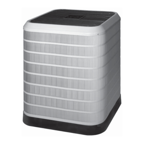
Premium Model Shown
IMPORTANT
Advertisement
Table of Contents
Troubleshooting

Related Manuals for Nordyne R-410A


Summary of Contents for Nordyne R-410A
- Page 1 Keep this literature where you have easy access to it in the future. If a problem occurs, check the instructions and follow recommendations given. If these suggestions don’t eliminate your problem, call your NORDYNE Servicing Contractor (Service PRO). These instructions are primarily intended to assist qualifi ed individuals experienced in the proper installation of this appliance.
-
Page 3: Table Of Contents
USER INFORMATION Operating the Heat Pump for Automatic Safety Information ........4 Cooling and Heating ........5 About the Heat Pump ........4 Oper. the Indoor Blower Continuously ..5 Operating Instructions ......... 4 Shutting the Heat Pump Off......5 Cooling Operation ........ -
Page 4: Safety Information
USER INFORMATION SAFETY INFORMATION OPERATING INSTRUCTIONS IMPORTANT: Safety markings are used Please refer to the thermostat manufacturer’s frequently throughout this manual to designate User manual for detailed programming a degree or level of seriousness and should not instructions. be ignored. WARNING indicates a potentially hazardous situation that if not avoided, could Cooling Operation Only result in personal injury or death. -
Page 5: Cooling And Heating
USER INFORMATION and the unit will defrost itself. This unit features SYSTEM MAINTENANCE Adaptive Demand Defrost that monitors ambient and coil temperatures to regulate the defrost CAUTION: function accordingly. At the beginning of the defrost cycle, both the Shut off all electrical power to the unit outdoor condenser fan and compressor will before performing any maintenance or turn off. -
Page 6: Pressures Within The System
INSTALLER INFORMATION SAFETY INFORMATION IMPORTANT: Safety markings are used CAUTION: frequently throughout this manual to designate a degree or level of seriousness and should not This unit uses refrigerant R-410A. DO be ignored. WARNING indicates a potentially NOT under any circumstances use any hazardous situation that if not avoided, could other refrigerant in this unit. -
Page 7: General Information
GENERAL INFORMATION SITE PREPARATION Split System Heat Pump units are designed for Unpacking the Equipment use with a wide variety of fossil fuel furnaces, Remove the shipping carton and User’s Manual electric furnaces, air handlers, and evaporator from the equipment. Take care not to damage the coil combinations equipped with variable speed tubing connections when removing the carton. -
Page 8: Roof Mount
Roof Mount • The maximum recommended interconnecting refrigerant line length is 75 feet, and the vertical WARNING: elevation difference between the indoor and outdoor sections should not exceed 20 feet. • If precise forming of refrigerant lines To avoid the risk of property damage, is required, a copper tubing bender is personal injury, or death, it is the recommended. -
Page 9: Outdoor Unit Connections
• Connect the line-voltage leads to the Grounding terminals on the contactor inside the control CAUTION: compartment. • Use only copper wire for the line voltage power supply to this unit (Table 1). Use proper code The unit must have an uninterrupted or agency listed conduit and a conduit connector unbroken electrical ground to minimize for connecting the supply wires to the unit. -
Page 10: Vac Power Wiring
again after the discharge pressure decreases to Interpreting the Diagnostic LED’s 460 psig. NOTE: When the switch opens and When an abnormal system condition occurs, the then closes, there will be a 3 minute short cycling Comfort Alert module displays the appropriate delay before the outdoor unit will energize. -
Page 11: Optional Equipment
Outdoor Fan Motor Thermostat If unit utilizes a 2-speed condenser fan motor, Set the thermostat’s system mode to OFF, the this motor will operate on low speed when in fan mode to AUTO, and adjust the temperature low cooling, and on high speed when in high setpoint to its highest setting. -
Page 12: Indoor Blower
verify system operation and compatibility with the Control is uncalibrated when power is applied. heat pump. Refer to the installation instructions Calibration occurs after a defrost cycle. The for this equipment and perform a functional control initiates this sacrifi cial defrost after 34 checkout in accordance with the manufacturer’s minutes of accumulated compressor run time in instructions. -
Page 13: Anti Short Cycle Timer Test
• If the REMOVE FOR NO DELAY jumper Assemblies of indoor coils and outdoor units is installed, the compressor will energize not listed are not recommended. immediately following a 30-second delay. Charging an R-410A Unit in AC Mode at Note: If the Y2 thermostat input is energized Outdoor Temperatures Above 65F. -
Page 14: Cooling Charging Charts
Cooling Charging Charts Remove refrigerant when above curve Add refrigerant when below curve 95 100 105 110 115 120 125 Liquid Temperature (° F) Figure 4. Charging Chart for 2 Ton Units Remove refrigerant when above curve Add refrigerant when below curve 100 105 110 115 120 125 Liquid Temperature (°... - Page 15 Cooling Charging Charts (continued) Remove refrigerant when above curve Add refrigerant when below curve 95 100 105 110 115 120 125 Liquid Temperature (° F) Figure 6. Charging Chart for 4 Ton Units Remove refrigerant when above curve Add refrigerant when below curve 95 100 105 110 115 120 125 Liquid Temperature (°...
-
Page 16: Heating Charging Chart
Heating Charging Chart Remove refrigerant when above curve Add refrigerant when below curve Liquid Temperature (° F) Figure 8. Heating Charging Chart... -
Page 17: Troubleshooting
TROUBLESHOOTING Status Status LED Status LED Troubleshooting Information Description Green Module has Supply voltage is present at module terminals “POWER” power • Compressor protector is open • Check for high head pressure Thermostat • Check compressor supply voltage demand signal •... - Page 18 TROUBLESHOOTING - CONTINUED Status LED Status LED Status LED Troubleshooting Information Description • Thermostat demand signal is intermittent Short Cycling • Yellow “ALERT” / Compressor Low line voltage (contact utility if voltage at disconnect is low) Flash Code 3 is running only •...
- Page 19 TROUBLESHOOTING - CONTINUED Miswired Module Indication Recommended Troubleshooting Action Green LED is not on, module • Determine if both R & C module terminals are connected. does not power up • Verify voltage is present at module’s R & C terminals. Green intermittent, •...
- Page 20 INSTALLER: PLEASE LEAVE THESE INSTALLATION INSTRUCTIONS WITH THE HOMEOWNER. ¢708868b¤ 708868A(Replaces 7088680) Specifi cations and illustrations subject to change without notice t incurring obligations. O’Fallon, MO 708868A Printed in U.S.A. (10/09)