Olympus FLUOVIEW FV1000 User Manual
Confocal laser scanning biological microscope
Hide thumbs
Also See for FLUOVIEW FV1000:
- User manual (540 pages) ,
- Overview (28 pages) ,
- Short instructions (7 pages)
Table of Contents
Advertisement
Petition
This user's manual is for the Olympus FLUOVIEW FV1000 Confocal Laser Scanning
Biological Microscope. To ensure safety, obtain optimum performance and familiarize
yourself fully with this product, we recommend that you study this manual thoroughly before
operation.
This user's manual is composed of three volumes including "SYSTEM
OVERVIEW", "PREPARATION FOR OPERATION" and "TROUBLE Q&A". Together
with this manual, please also read the "SAFETY GUIDE" of "User's manual
FLUOVIEW FV1000" and the instruction manual of the microscope in order to
understand overall operation methods. To ensure the safety operation of laser system,
we recommend you to study the manual of each laser and the light source equipment
besides this manual.
Retain this manual in an easily accessible place near a system for future reference.
FLUOVIEW
CONFOCAL LASER SCANNING
BIOLOGICAL MICROSCOPE
User's Manual
FV1000
[HARDWARE]
AX7282
Advertisement
Chapters
Table of Contents

Related Manuals for Olympus FLUOVIEW FV1000


Summary of Contents for Olympus FLUOVIEW FV1000
- Page 1 BIOLOGICAL MICROSCOPE [HARDWARE] Petition This user’s manual is for the Olympus FLUOVIEW FV1000 Confocal Laser Scanning Biological Microscope. To ensure safety, obtain optimum performance and familiarize yourself fully with this product, we recommend that you study this manual thoroughly before operation.
- Page 3 CAUTION CAUTION 1. Reproduction, copying or duplication of a part or all of this software and manual is prohibited. Registered Trademarks Microsoft, Microsoft Windows, Excel for Windows are registered trademarks of Microsoft Corporation. Other brand names and product names are trademarks or registered trademarks of their respective owners. Page...
-
Page 4: Table Of Contents
MANUAL CONFIGURATION MANUAL CONFIGURATION I. SYSTEM OVERVIEW 1. System Overview....................I. II. PREPARATION For OPERATION 1. Preparation for Operation ................II. 2. Replacement of Cubes ...................II. 3. Centration of Mercury Burner .................II. III. TROUBLE Q&A 1. Troubleshooting Guide ...................III. Page... - Page 5 NOTATIONS IN THIS MANUAL NOTATIONS IN THIS MANUAL This manual complies with the following notations. Notation of Caution, Notes and Tips Notation D e s c r i p t i o n Caution to prevent injuries to the user or damage to the product (including surrounding objects).
- Page 7 On This Volume This volume describes the overview of the FLUOVIEW FV1000 system. Please read this volume so that you can understand the system before use.
- Page 9 CONTENTS 1 System Overview 1-1 Principles 1-2 Features of the FV1000 1-3 Optical Path Diagram 1-4 System Configuration 1-4-1 System Diagram 1-4-2 System Appearance and Functions...
-
Page 11: System Overview
/ Principles 1 System Overview OLYMPUS FV1000 is a confocal laser scanning biological microscope system featuring improved basic performances (sensor system, scanning system and illumination system performances) by considering the “live cell observations”, with which long hours of stable measurement of weak fluorescence is required. -
Page 12: Features Of The Fv1000
System Overview / Features of the FV1000 1-2 Features of the FV1000 The photon counting mode is newly provided to improve the sensitivity and S/N and to enable quantitative optical intensity measurement. Photon counting makes possible long hours of quantitative observation by completely eliminating analog- derived drift. -
Page 13: Optical Path Diagram
System Overview / Optical Path Diagram 1-3 Optical Path Diagram Barrier filter Barrier filter Laser beam Grating Pinhole Galvano mirror Grating Slit Slit Mercury light Supply Galvano mirror I . System Overview I. 1 - 3 Page... -
Page 14: System Configuration
System Overview / System Configuration 1-4 System Configuration 1-4-1 System Diagram Mercury lamp Housing Epi Fiber Illumination LD405/440 Laser Non-confocal Point Detector for BX Unit VIS laser Fiber Unit Swinging Nosepiece Laser Combiner XLU Single-Position Nosepiece Microscope Argon laser Scan Unit Additional 4 Channel for BX... -
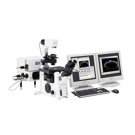
Page 15: System Appearance And Functions
System Overview / System Configuration 1-4-2 System Appearance and Functions The applicable microscopes are the BX61/62TRF, BX61WIF and IX81F. Epi Fiber Illumination Unit Laser Power Supply Microscope Mouse Keyboard Top View Power supply unit Also controls the FV1000 scan unit, laser combiner, etc. Epi Fiber Illumination Unit Illumination unit based on 20’... - Page 17 On This Volume This volume describes the methods for preparation for operation of the FLUOVIEW FV1000 system. After completing the preparations, activate the software and start observation by controlling the display on the monitor screen. Please read this volume so that you can understand the...
- Page 19 CONTENTS 1 Preparation for Operation 1-1 Turning the Power On 1-2 Starting the Software 1-3 Exiting from the Software 1-4 Turning the Power Off 2 Replacement of Cubes 2-1 Replacing the DM Cube 2-1-1 With the FV10-ASU 2-1-2 With the FV10-OPD 2-2 Replacing the Spectral Cube 2-2-1 Removing the spectral cube 2-2-2 Fabricating a spectral cube...
-
Page 21: Preparation For Operation
Preparation for Operation / Turning the Power On 1 Preparation for Operation 1-1 Turning the Power On 1. Set the power switches of the following units to I (ON). Power Supply Unit FV10-PSU Mercury Burner Power Supply Unit Microscope Control Box BX-UCB or IX2-UCB 2. - Page 22 Preparation for Operation / Turning the Power On 3.3 LD405/440 laser: FV10-LD405/440 Make sure that the provided shorting plug is attached to the remote interlock or that is connected to your equipment and the interlock is released. Set the power switch to ON.
-
Page 23: Starting The Software
Preparation for Operation / Starting the Software 1-2 Starting the Software Turn on the microscope and power supply units before starting this NOTE software. NOTE If you are [FV10-SW] user, don’t double click the [FLUOVIEW Setup] icon on the desktop and boot it up while the FLUOVIEW software is running. -
Page 24: Exiting From The Software
Preparation for Operation / Exiting from the Software 1-3 Exiting from the Software Exit from the application software and shut down Windows. NOTE After exiting the application software, the light of mercury burner power supply unit may exposure to specimen. To avoid this, perform either of the followings, ·... -
Page 25: Replacement Of Cubes
Replacement of Cubes / Replacing the DM Cube 2 Replacement of Cubes 2-1 Replacing the DM Cube The DM cube is used to connect the light path of the optional FV10-ASU Auxiliary Scan Unit or FV10-OPD Non-confocal Point Detector with that of the scan unit, and should be selected according to the observation method. - Page 26 Replacement of Cubes / Replacing the DM Cube Using the Allen screwdriver, loosen the clamping screw retaining the DM cube. Pull out the DM cube insertion knob toward you and take out the DM cube from the light path selector mechanism. Insert the desired DM cube in the dovetail of the light path selector mechanism, and tighten the clamping screw using the Allen screwdriver.
-
Page 27: With The Fv10-Opd
Replacement of Cubes Replacing the DM Cube 2-1-2 With the FV10-OPD Perform the same operations as steps 1 to 5 in section 2-1-1, “With the FV10-ASU” to take out the DM cube. Using a precision Phillips screwdriver, loosen the screw clamping the DM holder plate and take out the DM and DM holder plate. -
Page 28: Replacing The Spectral Cube
Replacement of Cubes / Replacing the Spectral Cube 2-2 Replacing the Spectral Cube To improve the efficiency of fluorescence detection, the fluorescence waveform separating dichroic mirrors and barrier filters (2 channels) of the spectral cube inside the external photo-multiplier (FV10-OPD) can be replaced according to the excitation wavelength to be used. - Page 29 Replacement of Cubes Replacing the Spectral Cube Loosen the spectral cube clamping screw a little using the Allen screwdriver, and pull out the spectral cube by holding the spectral cube insertion knob II. PREPARATION For OPERATION II. 2 - 5 Page...
-
Page 30: Fabricating A Spectral Cube
Replacement of Cubes / Replacing the Spectral Cube 2-2-2 Fabricating a spectral cube A desired spectral cube can be fabricated by attaching a commercially available barrier filter and DM to the spectral cube frame. Dimensional conditions for the optical components Barrier filter , max. -
Page 31: Centration Of Mercury Burner
Centration of Mercury Burner / Centering the Mercury Burner 3 Centration of Mercury Burner 3-1 Centering the Mercury Burner For the reflected light fluorescence observation, refer to the User’s Manual for the Reflected Light Fluorescence System. Since this system introduces the light of a mercury burner through the light guide, the burner centering method is slightly different from that described in the User’s Manual for the Reflected Light Fluorescence System. - Page 32 Centration of Mercury Burner / Centering the Mercury Burner Turn the collector lens focusing knob on the lamp housing to bring the arc image into focus. Hereafter, centering is possible with the method described in the User’s Manual for the Reflected Fluorescence System, that is, using the burner centering knob and mirror focusing screw.
-
Page 33: Trouble Q&A
This volume describes how to deal with troubles with the FLUOVIEW FV1000 system. If any irregularity is observed, read this volume before calling for service. If the irregularity cannot be resolved by the described remedial action, please contact Olympus for repair. - Page 35 CONTENTS 1. Laser is not output from the extremity of the objective. 2. Fluorescence image cannot be observed. 3. Transmitted image cannot be observed. 4. Image is disturbed. 5. Reflected light (laser light) enters the fluorescence image. 6. Fluorescence image is poor. 7.
-
Page 37: Troubleshooting Guide
The system may be unable to manifest its full performance due to its usage as well as malfunction. In case a problem occurs with the system please check the following list to find appropriate countermeasures. If the problem cannot be resolved by the described remedial action, please contact Olympus for repair. Irregularity Cause Remedy 1. -
Page 38: Fluorescence Image Cannot Be Observed
Decrease the offset value. light detection channel is too large. 4. Image is disturbed. The system installation location is Contact Olympus. subject to excessive vibrations. Extraneous light such as the light of a Turn the room light low before acquiring fluorescent lamp is detected. -
Page 39: Fluorescence Image Is Dark And Noisy
Troubleshooting Guide Irregularity Cause Remedy The excitation Dichroic Mirror Engage a DM optimum for the observed Fluorescence image is selection does not match the fluorescence and excitation laser dark and noisy. observed fluorescence wavelength wavelengths. and excitation laser wavelength. The spectral dichroic mirror and Engage a spectral DM and barrier filter barrier filter selections do not match matching the observed fluorescence in... -
Page 40: The Light From The Laser For The Asu (Additional Scan Unit) Is Not Output
Troubleshooting Guide Irregularity Cause Remedy 13. The light from the laser The properties of the combined DM Engage a DM cube unit matching the for the ASU (additional cube unit for ASU do not match the laser wavelength in the light path. scan unit) is not output. - Page 42 Postfach 10 49 08, 20034, Hamburg, Germany OLYMPUS AMERICA INC. 2 Corporate Center Drive, Melville, NY 11747-3157, U.S.A. OLYMPUS SINGAPORE PTE LTD. 491B River Valley Road, #12-01/04 Valley Point Office Tower, Singapore 248373 OLYMPUS UK LTD. 2-8 Honduras Street, London EC1Y OTX, United Kingdom.