Bosch Plena Voice Alarm System Installation And Operation Manual
Hide thumbs
Also See for Plena Voice Alarm System:
- Operating manual (192 pages) ,
- Installation and user instructions manual (124 pages) ,
- Installation and user instruction manual (72 pages)
Table of Contents
Advertisement
Quick Links
Advertisement
Table of Contents

Related Manuals for Bosch Plena Voice Alarm System


Summary of Contents for Bosch Plena Voice Alarm System
- Page 1 Plena Voice Alarm System Installation and Operation manual...
-
Page 3: Table Of Contents
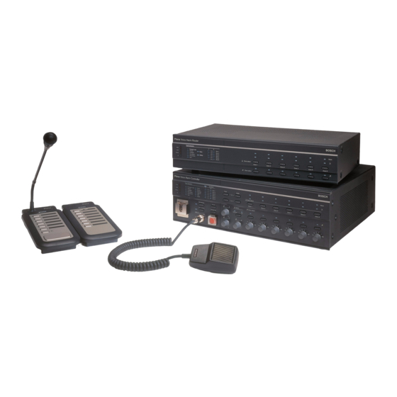
Plena Voice Alarm System Table of Contents | en Table of Contents Safety Important Safeguards Important Notices About this manual Purpose of this manual Intended audience Related documentation Alerts Signs Conversion tables Nomenclature System overview Voice Alarm System 3.1.1 Application types 3.1.2... - Page 4 | Table of Contents Plena Voice Alarm System 3.12.1 Schools 3.12.2 Swimming pool 3.12.3 Shopping mall 3.12.4 Hotel 3.13 Calls and priorities 3.13.1 Priority 3.13.2 Mergeable messages 3.13.3 Business call 3.13.4 Emergency call Installation Voice Alarm Controller Voice Alarm Router...
- Page 5 Plena Voice Alarm System Table of Contents | en 5.3.3 Keypads Voice Alarm Remote Control 5.4.1 Voice alarm controller 5.4.2 Remote control extensions 5.4.3 Status output contacts 5.4.4 Power Voice Alarm Remote Control Kit 5.5.1 Rear panel 5.5.2 LEDS 5.5.3 Lamps 5.5.4...
- Page 6 | Table of Contents Plena Voice Alarm System 6.3.5 Voice alarm router 6.3.6 Router ID 6.3.7 Termination switch Call station 6.4.1 Call station ID 6.4.2 Sensitivity 6.4.3 Speech filter 6.4.4 Termination Remote control 6.5.1 Remote control ID 6.5.2 Monitor 6.5.3...
- Page 7 Plena Voice Alarm System Table of Contents | en No BGM on controller or router No sound coming from the router Volume override only working for EMG, not for business calls (or similar problems) False Ground Short fault 8.10 Start/Stop function on Trigger Inputs 8.11...
- Page 8 | Table of Contents Plena Voice Alarm System A.2.2 Router address setting A.2.3 Backup power (Controller, Router, Power Amplifier) 9922 141 1037x (V2.16) | V0.6 | 2011.09 Installation and Operation manual Bosch Security Systems B.V.
-
Page 9: Safety
Plena Voice Alarm System Safety | en Safety Important Safeguards Prior to installing or operating this product, always read the Important Safety Instructions which are available as a separate document (9922 141 7014x). These instructions are supplied together with all equipment that can be connected to the mains. -
Page 10: About This Manual
Purpose of this manual The purpose of the Installation and Operation manual is to provide information that is required to install, configure and operate a Plena Voice Alarm System. Intended audience The Installation and Operation manual is intended for installers and users of an (extensive) Plena Voice Alarm System. -
Page 11: Conversion Tables
Plena Voice Alarm System About this manual | en Conversion tables In this manual, SI units are used to express lengths, masses, temperatures etc. These can be converted to non-metric units using the information provided below. 1 in = 25.4 mm 1 mm = 0.03937 in... - Page 12 | About this manual Plena Voice Alarm System Component description Component type designation Plena Power Amplifier 360/240W LBB1935/20 Plena Power Amplifier 720/480W LBB1938/20 Call Station LBB1956/00 Call Station Keypad LBB1957/00 Controller LBB1990/00 Router LBB1992/00 System Fireman's panel LBB1995/00 Remote Control...
-
Page 13: System Overview
Promatrix or other system. When an audio output of Praesideo is connected to a VOX audio input of the Plena Voice Alarm System, calls that are made by the Praesideo system overrule the calls that are made with the Plena Voice Alarm System. -
Page 14: Voice Alarm Controller
Plena Voice Alarm System Voice alarm controller The Voice Alarm Controller is the heart of the Plena Voice Alarm System. The voice alarm controller distributes emergency calls, business calls as well as background music (BGM) to up to 6 loudspeaker zones. -
Page 15: Controls, Connectors And Indicators
Plena Voice Alarm System System overview | en 3.2.7 Controls, connectors and indicators Plena Voice Alarm Controller Fault Indicators Disabled 0 dB Alarm Fault Processor reset Mains Zone1 Battery -6dB Network Zone2 Call/EMG Message Zone3 Zone select -20dB Music/Spare EMG mic... - Page 16 Six volume override outputs to override local volume controls in each zone (see section 5.1.7 ). 20. Status outputs: Three status outputs to send the status of the Plena Voice Alarm System to third party equipment (see section 5.1.11 ). 9922 141 1037x (V2.16) | V0.6 | 2011.09 Installation and Operation manual Bosch Security Systems B.V.
- Page 17 Plena Voice Alarm System System overview | en 21. Trigger inputs/24 V DC output: Twelve trigger inputs to receive signals from third party equipment and one 24 V(DC) output (see section 5.1.13 ). 22. Call station sockets: Two redundant RJ45 sockets to connect call stations to the voice alarm controller (see section 5.1.2 ).
-
Page 18: Voice Alarm Router
Also includes a 70 V connection. 45. Call output: An output that provides the call audio of the Plena Voice Alarm System. 46. Back-up power inlet: An inlet to connect a back-up power supply to the voice alarm controller (see section 5.1.12 ). -
Page 19: External Power Amplifiers
9, the maximum number of EMG trigger inputs in a Plena Voice Alarm System is 60. The maximum number of business trigger inputs in a Plena Voice Alarm System is also 60. 3.3.3 External power amplifiers The voice alarm router does not have an internal power amplifier. - Page 20 (no. 18). Call output: An output that provides the call audio of the Plena Voice Alarm System. Override outputs: Six volume override outputs to override local volume controls in each zone (see section 5.2.3 ).
-
Page 21: Call Station
(no. 18). Call Station The Call Station can be connected to the Plena Voice Alarm System to make business calls. The maximum number of call stations in a Plena Voice Alarm System is 8. -
Page 22: Keypad
| System overview Plena Voice Alarm System 3.4.3 Keypad Each voice alarm router can add 6 extra loudspeaker zones to the system. To be able to distribute calls to the extra zones, it is possible to connect Remote Control Extension to the call station. -
Page 23: Call Station Keypad
Plena Voice Alarm System System overview | en Push-to-talk button: A push-to-talk (PTT) button to start the business call. Status indicators: Three LEDs that indicate the status of the call station (see section 7.3.2 ). Keypad connector: A connector to connect call station keypads to the call station. -
Page 24: Voice Alarm Remote Control
| System overview Plena Voice Alarm System Voice Alarm Remote Control Plena Voice Alarm Remote Control Fault Indicators Disabled 0 dB Alarm Fault Processor reset Mains Zone1 Network Battery Zone2 -6dB Message Call/EMG Zone3 Zone select -20dB Music/Spare EMG mic... - Page 25 Plena Voice Alarm System System overview | en Emergency call zone selectors: Six buttons to select the zones to which the emergency call must be distributed (see section 7.4 ). Each button has a green and a red LED. The six red LEDs indicate the zones that are selected for the emergency call.
-
Page 26: Voice Alarm Remote Control Kit
23. Trigger outputs: Three general purpose trigger outputs. For future use. 24. Status outputs: Three status outputs to send the status of the Plena Voice Alarm System to third party equipment (see section 5.4.3 ). 25. 24 V DC input: One 24 V(DC) input to connect the remote control panel to a power supply (see section 5.4.4 ). -
Page 27: Remote Control Extension
Plena Voice Alarm System System overview | en Remote Control Extension Plena Remote Control Extension Fault Indicators Alarm 0 dB Processor reset Zone1 -6dB Network Mains Zone2 Call/EMG Zone3 -20dB Music/Spare Battery Zone4 Ground short Zone5 Zone select Input Zone6... -
Page 28: Remote Control Extension Kit
11. Trigger outputs: Three general purpose trigger outputs. For future use. 12. Status output: One status output to send the status of the Plena Voice Alarm System to third party equipment (see section 5.6.2 ). 13. 24 V DC input: One 24 V(DC) input to connect the remote control panel to a power supply (see section 5.6.3 ). -
Page 29: Fireman's Panel
Plena Voice Alarm System System overview | en 3.10 Fireman’s Panel 2 3 4 5 6 7 Plena Fireman's Panel Alarm Call Emergency Message Disable Fault Indicators 0 dB Processor reset Zone1 -6dB Network Call/EMG -20dB Zone2 Emergency Fault Music/Spare... - Page 30 18. Trigger outputs: Three general purpose trigger outputs. For future use. 19. Status outputs: Three status outputs to send the status of the Plena Voice Alarm System to third party equipment (see section 5.8.3 ). 20. 24 V DC input: One 24 V(DC) input to connect the fireman’s panel to a power supply (see section...
-
Page 31: End Of Line Detection Board
BGM in recreation areas is optional Solution for a 30-zone system The Plena Voice Alarm System Controller handles message routing to 6 zones, the remaining 24 zones require four additional 6-zone routers. The office is equipped with a call station plus keypads for individually addressing zones, while a fireman’s panel (with overall priority) is... - Page 32 | System overview Plena Voice Alarm System Power requirements The system controller features a built-in 240 W power amplifier, making it possible to drive up to 40 loudspeakers with a power handling capacity of 6 W each. This is sufficient for a medium-sized high school with 24 classrooms, 4 toilets/changing rooms, a staff meeting room and 2 offices, each requiring a single loudspeaker.
-
Page 33: Swimming Pool
– Solution for a 5-zone system The Plena Voice Alarm System controller handles routing to up to 6 zones, so no additional routers are required. The office/reception is equipped with a call station plus keypad for individually addressing zones, while a fireman’s panel (with overall priority) is built in by the emergency exit. -
Page 34: Shopping Mall
BGM music with local override in shops Solution for a 54-zone system A Plena Voice Alarm System Controller handles routing to 6 zones, the remaining 48 zones require eight 6-zone routers. The security control room is equipped with a remote control panel and call station plus keypads for individually addressing zones and BGM for the public areas, while the controller unit and routers are located in a fire-resistant cabinet or basement. - Page 35 Plena Voice Alarm System System overview | en Power requirements Each zone will have varying power requirements, ranging from small shops with a single loudspeaker to department stores with several floors and more loudspeakers. Parking garages and open-air walkways will require weatherproof sound projectors or horn loudspeakers. To facilitate phased evacuation from different levels of the shopping center, public areas are divided into zones.
-
Page 36: Hotel
(with overall priority) is built in by the emergency exit. The Plena Voice Alarm System is a two-channel system, so BGM can still be provided in zones not receiving a call. - Page 37 Plena Voice Alarm System System overview | en Power requirements The system controller features a built-in 240 W power amplifier, able to drive up to 40 loudspeakers (6 W). Additional Plena Power Amplifiers are incorporated to provide additional power, two-channel operation and spare amplification. To facilitate phased evacuation from different floors of the hotel, guest areas are divided into separate zones, each fitted with 13 ceiling loudspeakers in the corridors.
-
Page 38: Calls And Priorities
| System overview Plena Voice Alarm System 3.13 Calls and priorities As the Plena Voice Alarm System is a public address and emergency sound system, it is used to distribute background music, business calls and emergency calls. 3.13.1 Priority To each call, a priority is assigned. -
Page 39: Installation
Plena Voice Alarm System Installation | en Installation Voice Alarm Controller The voice alarm controller is suitable for table-top and 19-inch rack-mounting installation. Two brackets for rack-mounting are supplied. See Figure 4.1. Figure 4.1 Brackets for rack-mounting Make sure that there is a free space of at least 100 mm on both sides of the unit for ventilation. -
Page 40: Voice Alarm Remote Control
| Installation Plena Voice Alarm System Voice Alarm Remote Control The remote control is suitable for table-top and 19-inch rack mounting installation. Two brackets for rack-mounting are supplied. Installing a remote control is similar to installing a voice alarm controller (see section 4.1 ). The brackets can also be used to attach the remote control to a wall. -
Page 41: Installation Of A Single Eol
Plena Voice Alarm System Installation | en NOTICE! It is possible for the LED to turn off before the contact is opened or vice versa. This level difference is typically less than 500 mV. 4.8.1 Installation of a single EOL Connect the two cables at the end of the 100 V loudspeaker line to the Input 100V LS on the EOL board. - Page 42 | Installation Plena Voice Alarm System First EOL board Last EOL board Figure 4.5 Trigger input indication In the configuration program, set the Action Programming for the relevant input to Fault and EOL. Enter the Zone or Zone group that is monitored by the EOL board. The Zone group can be All Zones (of the Controller/Router), Zone 1-3 or Zone 4-6.
-
Page 43: Dummy Load
Plena Voice Alarm System Installation | en Dummy load To install the Dummy load do as follows: Connect the two leads onto the connection terminals of the last loudspeaker in a line. Attach the Dummy Load circuit board in the loudspeaker cabinet to the mounting studs. -
Page 44: Connection
| Connection Plena Voice Alarm System Connection Voice Alarm Controller 5.1.1 Emergency microphone The voice alarm controller has 1 connector for an emergency microphone. A hand-held emergency microphone is supplied with the voice alarm controller. See Figure 5.1 for installation details. -
Page 45: Voice Alarm Routers
Plena Voice Alarm System Connection | en 5.1.3 Voice alarm routers The voice alarm controller has 1 socket for Voice Alarm Routers. Use shielded Cat-5 Ethernet cables with RJ45 plugs to connect a voice alarm router to the voice alarm controller. When the system requires more than 1 voice alarm router, use the system sockets on the voice alarm router to make loop-throughs. -
Page 46: External Power Amplifier
| Connection Plena Voice Alarm System 5.1.4 External power amplifier The voice alarm controller has 1 external power amplifier output (line level, 1 V) and 1 external power amplifier input (100 V) to connect an external power amplifier (see Figure 5.4). -
Page 47: Remote Controls
Plena Voice Alarm System Connection | en 5.1.5 Remote controls The voice alarm controller has 2 sockets for remote controls. Use shielded Cat-5 Ethernet cables with RJ45 plugs to connect a remote control to the voice alarm controller. See Figure 5.5 for connection details... - Page 48 NOTICE! The impedance measurement of the Plena Voice Alarm System has an accuracy better than 2%. The system only generates a fault if the line impedance difference is greater than the configured accuracy. Use the configuration software to configure the accuracy...
-
Page 49: Volume Overrides
Plena Voice Alarm System Connection | en 5.1.7 Volume overrides The voice alarm controller has 6 override outputs; 1 for each zone in the system (see Figure 5.7). These are suitable for 4-wire override (24 V) and 3-wire override. NOTICE! By default, the voice alarm controller is configured for 4-wire (24 V), power-saving override, see situation I in Figure 5.9. - Page 50 | Connection Plena Voice Alarm System Normally, when there are no active calls, the Z+ pins are internally connected to the NC contact of the Volume Override. At the moment a call is started in a zone, the Z+ pin of the zone is internally connected to the NO contact of the Volume Override.
-
Page 51: Line Output
Plena Voice Alarm System Connection | en NOTICE! See the Configuration Software Manual (9922 141 1038x) for more information about the configuration software. CAUTION! Make sure that the correct connections have been made and the system is correctly configured. 100V 100V Figure 5.10 3-wire volume override... -
Page 52: Mic/Line Input With Vox
| Connection Plena Voice Alarm System 5.1.9 Mic/line input with VOX The voice alarm controller has 1 mic/line input with voice-activated (VOX) functionality (see Figure 5.12). This input has 2 sockets; a balanced XLR socket and a balanced 6.3 mm jack socket. -
Page 53: Bgm Inputs
The voice alarm controller has 3 status output contacts to indicate the current system state (see Figure 5.15). These are used to send the status of the Plena Voice Alarm System to third party equipment or to connect sounders or similar indicating devices. -
Page 54: Power
Table 5.2 Status output contact The status output contacts are internal relays. By default, NC is connected to COM. When the Plena Voice Alarm System enters one of the states that are indicated in Table 5.2, the relay connects NO to COM. -
Page 55: Trigger Inputs
The voice alarm controller has a terminal block to which 6 emergency (EMG) and 6 business trigger inputs can be connected. Third party systems can use the trigger inputs to start emergency and business calls in the Plena Voice Alarm System. The trigger inputs must be configured with the configuration software. - Page 56 | Connection Plena Voice Alarm System Emergency trigger inputs The upper part of the terminal block (see Figure 5.19) contains the emergency trigger inputs. The emergency trigger inputs have a higher priority than the business trigger inputs. DC out VOX Switch Figure 5.19 Connecting emergency trigger inputs...
-
Page 57: Voice Alarm Router
Third party systems can use the trigger inputs to start emergency and business calls in the Plena Voice Alarm System. The trigger inputs must be configured with the configuration software. The procedure for connecting trigger inputs to a voice alarm router is similar to the procedure for connecting trigger inputs to the voice alarm controller (see section 5.1.13 ). -
Page 58: External Power Amplifiers
| Connection Plena Voice Alarm System 5.2.5 External power amplifiers The voice alarm router has 2 external power amplifier outputs (line level, 1 V) and 1 external power amplifier input (100 V) to connect two external power amplifiers. The function of the external power amplifier (e.g. -
Page 59: Power
Plena Voice Alarm System Connection | en LBB1992/00 0 100V 0 100V 70V 0 100V 0 100V 0 100V 0 +24V- Booster 2 in DC In TRG1 TRG2 Booster 1 Booster 2 G ND G ND 100V 70V line in... -
Page 60: Call Station
| Connection Plena Voice Alarm System Call Station 5.3.1 Voice alarm controller Connect the call station to the voice alarm controller (see section 5.1.2 ). 5.3.2 Power supply If the cable between the voice alarm controller or the previous call station is longer than 100 m, the call station must be connected to a 24 V(DC) power source. -
Page 61: Voice Alarm Remote Control
Plena Voice Alarm System Connection | en Voice Alarm Remote Control 5.4.1 Voice alarm controller Connect the remote control panel to the voice alarm controller (see section 5.1.5 ). 5.4.2 Remote control extensions The remote controller has 1 socket for remote control extensions (Remote Control Extension, Remote Control Extension kit). -
Page 62: Voice Alarm Remote Control Kit
| Connection Plena Voice Alarm System Voice Alarm Remote Control Kit 5.5.1 Rear panel The rear panel of the remote control kit has the same connectors and controls as the rear panel of the Voice Alarm Remote Control. See section 5.4 for connection details. -
Page 63: Remote Control Extension
Plena Voice Alarm System Connection | en Remote Control Extension 5.6.1 Remote control Connect the remote control extension to the remote control (see section 5.4.2 ). 5.6.2 Status output contacts The remote control extension has 3 status output contacts to indicate the current system state. -
Page 64: Fireman's Panel
| Connection Plena Voice Alarm System Fireman’s Panel 5.8.1 Voice alarm controller Connect the fireman’s panel to the voice alarm controller (see section 5.1.5 ).? 5.8.2 Remote control extensions The fireman’s panel has 1 socket for remote control extensions (Remote Control Extension, Remote Control Extension kit). -
Page 65: Configuration
Configuration | en Configuration A number of functions of the Plena Voice Alarm System is hardware configured using, for example, DIP switches and volume controls. Other parts of the system must be software configured using the Plena Voice Alarm System configuration software. A description of this software is beyond the scope of this manual. -
Page 66: Supervision
| Configuration Plena Voice Alarm System – The emergency trigger inputs are never supervised. – When an emergency trigger input is activated, the system enters the emergency state. The voice alarm controller also automatically starts a pre-emergency announcement and alarm message (software configurable). -
Page 67: 2-Channel Mode Operation
Plena Voice Alarm System Configuration | en 6.1.5 2-Channel mode operation If the 2ch operation switch (see Figure 6.1) is in the ON position, the system operates in the 2- channel mode. Voice alarm controller In the 2-channel mode, the BGM is amplified by the internal power amplifier of the voice alarm controller. -
Page 68: Processor Reset
| Configuration Plena Voice Alarm System If the Supervision switch is in the ON position, an indicator is lit when a supervised function fails (see section 7.5 ). Use the configuration software to switch supervised functions on and off. -
Page 69: Emergency Trigger Inputs
Plena Voice Alarm System Configuration | en 6.2.5 Emergency trigger inputs If supervision is enabled and input supervision is switched on (see section 6.2 ), the system can supervise the emergency trigger inputs. For each emergency trigger input, supervision can be switched on and off with the configuration software. -
Page 70: Voice Alarm Controller
| Configuration Plena Voice Alarm System Short-circuit supervision If line supervision is switched on, the voice alarm controller continuously monitors all loudspeaker lines in the system for short-circuits. If a short-circuit is detected, the line output of the short-circuited line is isolated and shut down within 200 ms. -
Page 71: Vox
Plena Voice Alarm System Configuration | en 6.3.2 If the Vox switch is in the OFF position, the input is activated when the voltage of the signal of the source is above the specified threshold. If the Vox switch is in the ON position, the input is activated when the VOX Switch trigger input is closed (see also section 5.1.9 ). -
Page 72: Call Station Id
| Configuration Plena Voice Alarm System DIP switch Description 1, 2, 3, 4 Set the ID of the call station. See section 6.4.1 . 5, 6 Set the sensitivity of the call station. See section 6.4.2 . Switches the speech filter on (ON) and off (OFF). See section 6.4.3 . -
Page 73: Monitor
Plena Voice Alarm System Configuration | en 6.5.2 Monitor If the Monitor switch is in the ON position, the internal monitoring loudspeaker of the remote control is switched on. The volume of the monitoring loudspeaker is set with the Monitoring Speaker volume control on the rear panel of the remote control. -
Page 74: Operation
| Operation Plena Voice Alarm System Operation Switch on NOTICE! It is assumed that the APR mode switch (see section 6.1.2 ) is in the OFF position. 7.1.1 Voice alarm controller Switch on Put the Power switch on the rear of the voice alarm controller (see Figure 7.1) in the I position. -
Page 75: Background Music
Plena Voice Alarm System Operation | en Background music The background music (BGM) is controlled using the BGM controls on the front of the voice alarm controller, voice alarm router and their remote control and remote control extensions. Proceed as follows to route BGM: Select the BGM source (see section 7.2.1 ). -
Page 76: Adjust Volume
| Operation Plena Voice Alarm System 7.2.3 Adjust volume The voice alarm controller has two types of controls to adjust the BGM volume (see Figure 7.5). The overall (maximum) volume of the BGM source is set with the master volume control, which is located below the BGM source selector (Select button, see Figure 7.3). -
Page 77: Select Zones
Plena Voice Alarm System Operation | en 7.3.1 Select zones Select the zones to which the business call must be distributed with the zone selection buttons on the call station or its keypads. A green LED indicates the zones to which the business call is distributed. -
Page 78: Emergency State
| Operation Plena Voice Alarm System Emergency state Emergency calls can only be distributed when the system is in the emergency state. See section 7.4.1 for information about entering the emergency state. In the emergency state, it is possible to distribute the following emergency calls: –... -
Page 79: Acknowledge The Emergency State
Plena Voice Alarm System Operation | en 7.4.2 Acknowledge the emergency state The beeper can be switched off by acknowledging the emergency state with the EMG Ack button on the voice alarm controller and the remote controls (see Figure 7.9). The beeper can also be switched off by acknowledging the emergency state with the Emergency Acknowledge button on the fireman’s panel. -
Page 80: Make The Announcement
| Operation Plena Voice Alarm System To select all zones, push the All call buttons on the front of the voice alarm controller or the remote controls (see Figure 7.12). Alert message All call Alarm message Indicator test EMG mic Figure 7.12 All call button... -
Page 81: Distribute The Alert Message
Plena Voice Alarm System Operation | en 7.4.7 Distribute the alert message Proceed as follows to distribute the default alert message: – Select the zones. – Start the alert message. Select zones Select the zones to which the default alert message must be distributed with the Zone select buttons on the front of the voice alarm controller or the remote controls (see Figure 7.15). -
Page 82: Distribute The Alarm Message
| Operation Plena Voice Alarm System 7.4.8 Distribute the alarm message Distributing the default alarm message is similar to distributing the default alert message (see section 7.4.7 ). Push the Alarm message button instead of the Alert message button (see Figure 7.18). -
Page 83: Fault State
Plena Voice Alarm System Operation | en Fault State If a supervised function fails, the system enters the fault state and: – Starts a beeper. The beeper is switched off when the fault is acknowledged (see section 7.5.1 ). –... -
Page 84: Fault Indicators
(see Figure 7.21) and loudspeaker line fault indicators (see Figure 7.22). The system fault indicators provide information about failing system functions that are supervised (see Table 7.2). If a system fault is persistent, contact your Bosch representative. - Page 85 Plena Voice Alarm System Operation | en Indicator Description Recommended action Additional information Processor A processor reset is Switch the voice alarm See section 6.2.1 . reset detected. controller off and on again. Network A network fault is Check all network See section 5.1.2 and...
- Page 86 | Operation Plena Voice Alarm System Indicator Description Recommended action Additional information A remote control panel Contact your dealer. This fault should not fault is detected. occur, since this type of supervision is disabled. Router A router fault is...
-
Page 87: Troubleshooting
Troubleshooting Introduction Although the Plena Voice Alarm System is simple and easy in general, still questions may arise. Maybe because of inexperience or maybe because of exploring limits of what the Plena Voice Alarm can do. In practice often the same questions reoccur. In other cases questions can be foreseen. -
Page 88: No Sound Coming From The Router
| Troubleshooting Plena Voice Alarm System No sound coming from the router Please check, if you are using a Plena Power Amplifier 720/480W, if the Line signal is connected to the Program Input. If the line signal is connected to the Priority Input instead of the Program Input there will be no output signal on the amplifier’s loudspeaker output. -
Page 89: Processor Reset
Plena Voice Alarm System Troubleshooting | en Figure 8.2 Silent message action programming When the alarm is stopped with the Trigger Input Stop all zones will be silent but the system will still be in Emergency State. The end user then needs to press Emergency Acknowledge and Emergency Reset to terminate this Emergency State. -
Page 90: A Click Sounds Through The Loudspeakers At Regular Intervals
| Troubleshooting Plena Voice Alarm System 8.14 A click sounds through the loudspeakers at regular intervals In a very silent environment like meeting rooms and offices, especially when they are abandoned, a small click can be heard at the start and end of an impedance measurement. - Page 91 Router # Output Z# Zone Group Group # Table 8.1 Default file names The wave files will be stored in the folder C:\Program Files\Bosch\Plena Voice Alarm System\Configuration\Sounds\Backup. Bosch Security Systems B.V. Installation and Operation manual 9922 141 1037x (V2.16) | V0.6 | 2011.09...
-
Page 92: Maintenance
| Maintenance Plena Voice Alarm System Maintenance The system requires minimum maintenance. To keep the system in good condition, do the following: – Clean the units (section 9.1 ) – Clean the air inlets (section 9.2 ) – Check connectors and grounding (section 9.3 ). -
Page 93: Technical Data
Plena Voice Alarm System Technical data | en Technical data 10.1 Electrical 10.1.1 Voice Alarm Controller Electrical Mains voltage: 230/115 V(AC), ± 10%, 50/60 Hz Mains current: 0.3 A (system idle) 4.0 A (maximum load) Max. mains inrush current: 6.3 A (for mains voltage of 220 - 240 V) - Page 94 | Technical data Plena Voice Alarm System Internal power amplifier Rated output power: 240 W Frequency response: 100 Hz - 18 kHz (+1/-3 dB, @ -10 dB ref. rated output) Distortion: < 1% @ rated output power, 1 kHz Signal-to-noise ratio (flat at max.
-
Page 95: Voice Alarm Router
Plena Voice Alarm System Technical data | en Mic/line input with VOX functionality Type: 3-pin XLR, 6.3 mm jack socket, balanced Sensitivity: 1 mV +1/-3 dB (mic), 1 V +1/-3 dB (line) Impedance: > 10 kΩ VOX threshold: 500 µV (mic), 500 mV (line) -
Page 96: Call Station
| Technical data Plena Voice Alarm System Loudspeaker outputs Type: Screw terminals Number of zones: Number of loudspeaker lines: 12 (2 per zone) Signal-to-noise ratio (flat at max. volume): > 85 dB Line voltage: 100 V Overrides Type: 3-wire or 4-wire on screw terminals... -
Page 97: Physical Characteristics
Plena Voice Alarm System Technical data | en Interconnection Type: 2x redundant RJ45 sockets to connect the call station to the voice alarm controller with Cat-5 Ethernet cables. 10.2 Physical characteristics 10.2.1 Voice Alarm Controller Dimensions: 19” wide, 3 U high, 360 mm deep (leave 50 mm for connections) 19”... -
Page 98: Remote Control Extension Kit
| Technical data Plena Voice Alarm System 10.2.8 Remote Control Extension Kit Current consumption: 50 mA (idle) 200 mA (indicator test) Dimensions: 88 x 432 x 90 mm Weight: 1.8 kg 10.2.9 Fireman’s Panel Current consumption: 150 mA (idle) -
Page 99: A Appendices
A.1.1 Emergency Sound Systems Bosch Security Systems has made a great effort for the design and manufacturing of the components and also supplies all documentation that enables the assembly of a safe and high quality emergency unit in accordance with EN60849:1998, EN54-16:2008 and ISO7240- 16:2007. - Page 100 100 en | Plena Voice Alarm System List of authorized end-users Name Name 9922 141 1037x (V2.16) | V0.6 | 2011.09 Installation and Operation manual Bosch Security Systems B.V.
-
Page 101: En60849: 1998 (Valid For Version 2.13.Xx)
Plena Voice Alarm System | en 101 A.1.2 EN60849: 1998 (valid for version 2.13.xx) 4. General system requirements Clause / Requirement Compliance Signature 4.1 Principal features A sound system for emergency purposes shall Compliant, if properly installed. The permit the broadcasting of intelligible... - Page 102 102 en | Plena Voice Alarm System Clause / Requirement Compliance Signature Unless damaged as a result of the Compliant, if all requirements below are emergency, the system shall be available for fulfilled and installed with: operation at all times (or as required by the –...
- Page 103 Plena Voice Alarm System | en 103 Clause / Requirement Compliance Signature The system shall be able to broadcast Compliant, if attention-drawing signal is attention-drawing signals and speech part of the configuration. Responsibility messages to one or more areas of the installer simultaneously.
- Page 104 104 en | Plena Voice Alarm System Clause / Requirement Compliance Signature The language(s) used shall be specified by Responsibility of the installer. the purchaser. The system shall be capable of being divided Compliant, if properly installed. into emergency loudspeaker zones if Responsibility of the installer.
- Page 105 Plena Voice Alarm System | en 105 Clause / Requirement Compliance Signature Evacuate - potentially life-threatening Compliant, if properly installed. situation needing immediate evacuation. Responsibility of the installer. Alert - dangerous situation nearby requiring Compliant, if properly installed. warning of pending evacuation.
- Page 106 4.4 Safety requirements The safety requirements applying to emergency Compliant. The Plena Voice Alarm System sound systems are given in IEC60065 or other complies with IEC60065. appropriate IEC safety standards.
- Page 107 Plena Voice Alarm System | en 107 Clause / Requirement Compliance Signature The system specification may exclude from the Responsibility of the installer. area of coverage, defined areas rarely or never occupied by people. 5.2 Automatic status indication A clear indication shall automatically be given at the designated control locations of: System availability.
- Page 108 108 en | Plena Voice Alarm System Clause / Requirement Compliance Signature Amplifiers or critical modules missing. Compliant. Fault is indicated on the controller and router. Configuration must be set up to supervise this. Failure of any standby amplifier. Compliant. Fault is indicated on the controller and router.
- Page 109 Plena Voice Alarm System | en 109 Clause / Requirement Compliance Signature The correct execution of the system software by any microprocessor shall be monitored by internal self-checking procedures and by an appropriate monitoring circuit (e.g. "watch dog" circuit) complying with the following: The monitoring circuit and its associated Compliant.
- Page 110 110 en | Plena Voice Alarm System Clause / Requirement Compliance Signature The emergency detection system shall also be Compliant, if properly installed using capable of receiving information regarding faults in trigger outputs. Responsibility of the the sound system and shall include a provision, installer.
- Page 111 5.7 Climate and environmental conditions As all or part of the system may be installed inside The Plena Voice Alarm System or outside buildings, under various climatic and specifications exceed the environmental conditions, and exposed to possible...
- Page 112 112 en | Plena Voice Alarm System Clause / Requirement Compliance Signature Control and amplification equipment and associated battery power supplies: – Ambient temperature -5 °C to + 40 °C. – Relative humidity 25% to 90%. – Air pressure 86 kPa to 106 kPa.
- Page 113 Plena Voice Alarm System | en 113 Clause / Requirement Compliance Signature Precautions shall be taken to prevent the spread of Responsibility of the installer. hazardous effects via the wiring routes. When a sound system for emergency purposes is Responsibility of the installer.
- Page 114 114 en | Plena Voice Alarm System Clause / Requirement Compliance Signature Installation details of the locations of all items of the Responsibility of the installer. equipment. “as installed” performance measurements Responsibility of the installer. of the system including: –...
-
Page 115: En60849 - When Using The Plena Remote Control Kits
Plena Voice Alarm System | en 115 Clause / Requirement Compliance Signature A stiff-covered maintenance manual should be Responsibility of the installer to available giving details of all work required to establish the maintenance procedures maintain the installation and equipment in proper using the manufacturer documentation. - Page 116 Certification Bodies, are valid for the products listed in the table below, which are part of the Plena Public Address and Emergency Sound System. There are two versions of the Plena Voice Alarm System hardware. For EN54-16 certification in Europe the hardware versions are as follows:...
- Page 117 Plena Voice Alarm System | en 117 Figure 1.1 EN54-16 label Bosch Security Systems B.V. Installation and Operation manual 9922 141 1037x (V2.16) | V0.6 | 2011.09...
- Page 118 4.3 Power supply Plena Voice Alarm System is compliant. 9922 141 1037x (V2.16) | V0.6 | 2011.09 Installation and Operation manual Bosch Security Systems B.V.
- Page 119 VACIE, shall comply with power supplies and battery charging the requirements of EN 54-4. equipment in accordance with EN 54-4. The Bosch PLN-24CH12 is compliant to EN54-4. NOTE - The power supply may be shared The power supply may be shared with that...
- Page 120 Plena Voice Alarm System is compliant. 5.1.1 The VACIE shall be capable of See Clauses 6 to 9. unambiguously indicating the following Plena Voice Alarm System does not have a functional conditions, as described in Clauses disablement function. 6 to 9: –...
- Page 121 VACIE is supplied with power. 5.4.2 Where the VACIE is distributed in more The Plena Voice Alarm System can be than one cabinet, an indication of supply of distributed in more than one cabinet, power to each distributed cabinet shall be depending on the installation of the system.
- Page 122 However, no indications shall be given which could be confused with indications used in the – voice alarm condition, If the Plena Voice Alarm System enters the voice alarm condition, controller, remote control panels (including fireman’s panel), and each call station will show a red system status LED.
- Page 123 NOTE - See Annex E for additional information If input contacts are used for connection of relating to the interface between the VACIE the CIE to the Plena Voice Alarm System then the input contacts can be monitored and the CIE.
- Page 124 7.4 Delays to entering the voice alarm condition (option with requirements) The VACIE may be provided with a facility to Since the Plena Voice Alarm System does introduce a delay before entering the voice not process the fire sensors, this functionality is better handled by the alarm condition.
- Page 125 This indication shall be suppressed when the VACIE enters the voice alarm condition. 7.5 Phased evacuation (option with Plena Voice Alarm System does not requirements) accommodate phased evacuation. The VACIE may have a provision to phase the warning signals to the emergency loudspeaker zones.
- Page 126 Plena Voice Alarm System is compliant. (option with requirements) The VACIE may have provision for transmitting The Plena Voice Alarm System transmits a a signal that is in the voice alarm condition. In signal that it is in the voice alarm condition...
- Page 127 8.2 and, if provided, in 8.3 unless this is prevented by: – the presence of an alarm output signal on the All Plena Voice Alarm System faults are handled (acknowledged and reset) same voice alarm zone, and/or collectively. The faults are indicated...
- Page 128 Plena Voice Alarm System does not have been suppressed shall be indicated; an alphanumeric display. suppressed fault indications shall be capable...
- Page 129 The Plena Voice Alarm System does not transmission path between the VACIE and offer this functionality directly: control inputs are supervised, but control fire alarm devices when used (see 7.8).
- Page 130 System faults are individually reported by means of the general fault warning indicator the Plena Voice Alarm System and can be and a separate light emitting indicator on the inspected using the front panel menu of VACIE.
- Page 131 Open Interface. 8.4.2 Since the Plena Voice Alarm System does not offer automatic reset from the fault The audible indication shall be silenced warning condition this requirement does automatically if the VACIE is automatically reset not need to be implemented.
- Page 132 8.6 Transmission of the fault warning Plena Voice Alarm System is compliant. condition The VACIE shall have provision for transmitting, The Plena Voice Alarm System controller by means of at least general fault signal, all faults has a fixed fault output.
- Page 133 Plena Voice Alarm System | en 133 9 Disablement condition (option with requirements) Compliance Signature Clause / Requirement 9.1 General requirements Praesideo does not support the disablement condition. 9.1.1 Disablements in accordance with the requirements of 9.4 shall inhibit all...
- Page 134 134 en | Plena Voice Alarm System Compliance Signature Clause / Requirement suppressed disablement indications shall be capable of being displayed by means of a manual operation at access level 1 or 2 which interrogates only disablement indications. 9.4 Disablements and their indication Voice alarm zones may be capable of being independently disabled and re-enabled.
- Page 135 (the The voice alarm condition is indicated on General Voice Alarm Output activated the Plena Voice Alarm System in general by a red indicator inside the EMG button on indicator), and the controller, routers and remote control panels.
- Page 136 The voice alarm condition is indicated on alphanumeric display for each voice alarm the Plena Voice Alarm System per zone by a zone and/or an indication for group(s) of red indicator on the controller, routers and voice alarm zones.
- Page 137 Clause / Requirement Compliance Signature The VACIE may have provision for interfacing to Plena Voice Alarm System does not external control device(s) such as standardized support the Interface to external control user interfaces required by local regulations. In device(s) option.
- Page 138 12 Emergency microphone(s) (option with requirements) Clause / Requirement Compliance Signature 12.1 General Plena Voice Alarm System is compliant. The VACIE may have provision for emergency Plena Voice Alarm System offers two microphone(s). In this case the emergency types of emergency microphones with...
- Page 139 Plena Voice Alarm System | en 139 Clause / Requirement Compliance Signature 12.2.1 Where more than one emergency Configuration of the emergency microphone can be connected to the VACIE, microphones is performed via the PC the emergency microphones shall be interface of the controller.
- Page 140 VACIE; own development process, Standard Development Process or SDP. Rules for the design of all elements of the Plena Voice Alarm System can be found in the TPD (document repository). In the SDP repository all process descriptions, process implementation documents, templates, guidelines, etc.
- Page 141 Plena Voice Alarm System | en 141 Clause / Requirement Compliance Signature the optional functions with requirements of this European Standard, the functions relating to other parts of EN 54, and the ancillary functions not required by this European Standard;...
- Page 142 IP30 of EN 60529:1991+A1:2000. 13.3.2 All interconnections and settings inside If the installer ensures that the physical access to the Plena Voice Alarm System the cabinet shall be accessible at level 3. is restricted to access level 3, all interconnections and settings inside the cabinet (e.g.
- Page 143 Plena Voice Alarm System, except those relating to the power supplies. except for the fault warning indication (global and individual) in order to report the failure of a power source.
- Page 144 The correct functioning of the Plena Voice Alarm System or of any other voice alarm transmission path is therefore not affected. The fault will be reported.
- Page 145 Plena Voice Alarm System is achieved by between distributed cabinets of a VACIE does means of the system bus. not prevent the activation of a voice alarm output...
- Page 146 Access level 1 is intended for operational users of the Plena Voice Alarm System. It provides direct (unrestricted) operational access to the Plena Voice Alarm System via: –...
- Page 147 System at access level 1 are accessible accessible without special procedures; without special procedures. indications and manual controls that are All Plena Voice Alarm System indications mandatory at access level 1 shall also be (LEDs, equipment connected to output contacts, front panel display) and manual accessible at access level 2;...
- Page 148 13.7.3 If the same light emitting indicators are Disablement indication is not available in used for the indication of specific faults and the Plena Voice Alarm System since Plena disablements, fault indications shall be flashing Voice Alarm System does not support the and disablement indications shall be steady.
- Page 149 | en 149 Clause / Requirement Compliance Signature 13.8 Indications on alphanumeric Plena Voice Alarm System does not have displays an alphanumeric display. 13.8.1 If an alphanumeric display consists of elements or segments, the failure of one of these shall not affect the interpretation of the displayed information.
- Page 150 13.9.2 The use of different colors is not The Plena Voice Alarm System do not use necessary for indications on alphanumeric alphanumeric displays. displays. However, if different colors are used for different indications, the colors used shall be as specified in 13.9.1.
- Page 151 13.12.2 Signal-to-noise ratio The VACIE shall have an A-weighted signal-to- The A-weighted signal-to-noise ratio of the Plena Voice Alarm System amplifiers noise ratio of at least 45 dB (see IEC 60268-1). (Power Amplifiers and Basic Amplifiers) is specified in the data sheets and in the IUI.
- Page 152 13.13 Message store(s) Plena Voice Alarm System is compliant. Pre-recorded messages shall be stored in non- The pre-recorded messages of the Plena volatile memory that retains the messages when...
- Page 153 Compliance Signature 13.14.1 The VACIE may have provision for at least The Plena Voice Alarm System has a minimum of one main amplifier and one one spare power amplifier. In this case: call amplifier. It has a maximum of one...
- Page 154 Plena Voice Alarm System is compliant. manufacturer's declarations In order to fulfill requirements of this European The Plena Voice Alarm System is centrally Standard the VACIE may contain elements which controlled by the software running on the are controlled by software. In this case, the controller.
- Page 155 This documentation shall comprise at least the following: a description of each module of the program, The Plena Voice Alarm System software as it is implemented in the source code of component descriptions (module descriptions) are available from the the program, containing: software architecture documents.
- Page 156 This safe state shall not result in the false activation of mandatory outputs. 14.5 The storage of programs and data Plena Voice Alarm System is compliant. (see also Annex C) 9922 141 1037x (V2.16) | V0.6 | 2011.09 Installation and Operation manual...
- Page 157 Also transferring message sets to the Plena Voice Alarm System is data-driven and is not part of the program executable. Therefore alteration of the site specific data does not affect the structure of the program.
- Page 158 2 or 3. reference. 14.6 Monitoring of memory contents Plena Voice Alarm System is compliant. The contents of the memories containing the site The message store is checked every 100 specific data shall be automatically checked at s using checksum validation.
- Page 159 The name ‘Bosch’ is visible on each element of the Plena Voice Alarm System. It or supplier; is the responsibility of the installer to ensure that this name is legible at access level 1 for all system elements.
-
Page 160: Hardware
160 en | Plena Voice Alarm System 16 Tests Clause / Requirement Compliance Signature Test have been carried out during certification of the Plena Voice Alarm System. 3.0 Hardware A.2.1 Introduction For the APR region hardware version 3.0 has been developed, with the following difference: –... - Page 162 Bosch Security Systems B.V. Kapittelweg 10 4800 RA Breda The Netherlands www.boschsecurity.com © Bosch Security Systems B.V., 2011...