Table of Contents
Advertisement
Quick Links
Advertisement
Table of Contents

Related Manuals for Bosch NurseCall Main Unit


Summary of Contents for Bosch NurseCall Main Unit
- Page 1 NurseCall Main Unit F.01U.252.699 | V1.1 | 2012.01 User Manual...
-
Page 3: Table Of Contents
NurseCall Main Unit Table of Contents | en Table of Contents Safety instructions Importance of safety instructions Disregarding safety rules Environmental conditions General safety instructions 1.4.1 Observation and information Description General description 2.1.1 Top view 2.1.2 Bottom view 2.1.3 Front view 2.1.4... - Page 4 | Table of Contents NurseCall Main Unit 4.2.3 Locating mode 4.2.4 Display mode Parameters 4.3.1 Access to parameters 4.3.2 List of parameters 4.3.3 Programming the unit language 4.3.4 Date and time setting 4.3.5 RS-232 output setting 4.3.6 Local acknowledgement setting 4.3.7...
- Page 5 NurseCall Main Unit Table of Contents | en "Alarm Transmitter NOT stored" message "Alarm Transmitter already stored" message "Ack. Transmitter NOT stored" message "Ack. Transmitter already stored" message The green button does not work Maintenance Checking the system Monitoring the power supply...
-
Page 6: Safety Instructions
Environmental conditions NOTICE! The NurseCall Main Unit must not be located near a water tap or any other source of water. The electrical safety of the unit is only guaranteed if the electrical installation is conform to the national regulation and if this installation works properly. -
Page 7: Observation And Information
Avoid touching conductive parts inside the unit if not absolutely necessary. CAUTION! Never let any liquid enter the system. In case of liquid spill inside the NurseCall Main Unit, act immediately as follows: Switch off the unit using the main switch under the casing. -
Page 8: Description
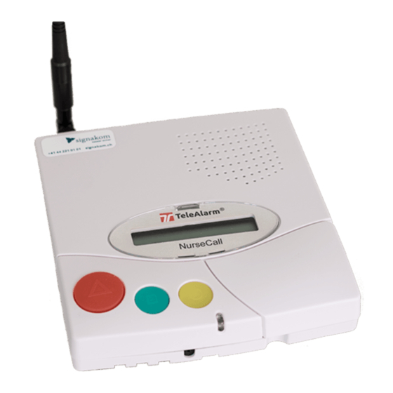
| Description NurseCall Main Unit Description General description 2.1.1 Top view Loudspeaker. See Section 2.2.1 Loudspeaker, page 11. Display. See Section 2.2.2 Display, page 11. Keyboard, under the cover. See Section 2.2.3 Keyboard, page 11. LED Indicator Yellow button Used to view more details about the event or alarm currently displayed (date and time, position, etc...). -
Page 9: Bottom View
NurseCall Main Unit Description | en 2.1.2 Bottom view Identification label. Cable channels. Wall mounting holes (distance between holes, 157 mm). See Section 3.2.3 Wall installation, page 16 for a detailed description. ON/OFF switch. LINE socket, used for firmware update. -
Page 10: Front View
| Description NurseCall Main Unit 2.1.3 Front view LED Indicator Status Standby mode (normal operation) Green (permanent) Backup battery low Green (blinking) Power supply disconnected Green (flashing) Help, assistance or fire Red (blinking) Programming mode Orange (blinking) 2.1.4 Rear view RS-232 connector See Section A.7.3 RS-232 socket (unit rear), page 59 for wiring. -
Page 11: Detailed Description
Local acknowledgement Short beep 2.2.2 Display The NurseCall Main Unit is equipped with a 2 x 20 characters display that guides the operator during the programming. During normal operation, alarms and messages are displayed. NurseCall Main Unit V2.01 BN111.240.00A NOTICE! This user manual is written for the unit language English USA. - Page 12 | Description NurseCall Main Unit Keys Programming Mode Normal Operation Access to parameters programming. Not used. See Section 4.3 Parameters, page 25. Access to transmitters programming. Not used. See Section 4.5 Transmitters, page 38. Scroll up to the next parameter.
-
Page 13: Rs-232 Interface
Printers with a parallel port can be used together with an intermediate serial - parallel converter. NOTICE! The paper printout corresponds to the indication at the display of the NurseCall Main Unit. Characteristics – Data rate: 9600 Bauds. -
Page 14: Rs-485 Interface
NurseCall Main Unit 2.2.5 RS-485 interface One NurseCall Main Unit and up to 32 NurseCall Relay Units can be connected by a RS-485 bus. The bus must be connected to pins 2 and 5 of the RS-485 socket. For connector wiring, see Section A.7.4 RS-485 socket (unit rear), page 59. -
Page 15: Installation
The components contained in the box are protected, but should be handled with care. Store the packaging material for further use (storage or transport). Take all components out of the box and place the NurseCall Main Unit on the working space. -
Page 16: Installation
3.2.3 Wall installation You can fasten the NurseCall Main Unit on a smooth wall surface using two screws. The distance between holes is 157 mm. Power and phone line cords should be placed inside the cable channels on the bottom of the NurseCall Main Unit. -
Page 17: Connecting To The Mains
Installation | en 3.2.5 Connecting to the mains The NurseCall Main Unit is powered by an adaptor (230/10 VAC or 115/10 VAC). CAUTION! In case of a different supply, the equipment must fulfill isolation requirements according to EN60950 standard (last edition). -
Page 18: Setting The Jumpers On The Communication Board
| Installation NurseCall Main Unit 3.2.7 Setting the jumpers on the communication board Disassemble the unit; see Section 7.5.1 Disassembling the unit, page 48. Remove the communication board; see Section Removing the communication board, page 48. Set the jumpers as required in your configuration. By default the jumpers are set for connection to a DECT phone system. -
Page 19: Connecting The Rs-485
Installation | en 3.2.8 Connecting the RS-485 One NurseCall Main Unit and up to 32 NurseCall Relay Units can be connected to an RS-485 bus. Please contact a specialist for a correct installation. See Section A.7.4 RS-485 socket (unit rear), page 59 for connector wiring. -
Page 20: Setting The 100 Ohm Termination Jumper
Section 7.5.1 Disassembling the unit, page 48. NOTICE! If you do not want to disassemble the NurseCall Main Unit, you also can short-out pins 3 and 4 of the connector. This has the same effect as the jumper setting described above. -
Page 21: Programming
Generalities NOTICE! In the programming mode, the NurseCall Main Unit does not display any alarm or message! The NurseCall Main Unit can be programmed either remotely by using a specific software package called NPS or directly by using the keyboard and display. -
Page 22: Programming With The Nps Software
Programming with the NPS software The NurseCall system can be programmed with a specific software called NPS. NOTICE! In order to program the NurseCall Main Unit with this software, you should connect your PC to the NurseCall Main Unit with an RS-232 cable. ... -
Page 23: List Of Original Factory Settings
NurseCall Main Unit Programming | en 4.2.1 List of original factory settings Parameter Original Factory Setting Page Language English USA * Locating mode * Display mode Floor/room/bed Output RS-232 None Forwarding of transmitter ID via the RS-232 interface RPE 670 / i-page for paging systems... -
Page 24: Language
It is mandatory to perform a reset if you wish to change the value for the locating mode. See Section 4.4.2 Resetting all the parameters, page 34. Enable (ON) or disable (OFF) the indication of the transmitter position (locating mode) on the NurseCall Main Unit display. LOCATING ? ( OFF / ON ... -
Page 25: Parameters
NurseCall Main Unit Programming | en Parameters 4.3.1 Access to parameters Press then to access the parameters. ¬ OK:Program ¤:Info Press to program these parameters or to check the value of each parameter. ¬ Parameter Nr. 00 Language £ Scroll with . -
Page 26: Date And Time Setting
| Programming NurseCall Main Unit Press ¬ Language 0 English USA £ Select the language with Confirm the language selected with NOTICE! This user manual is written for the unit language English USA. Certain displays may differ for the unit language English UK. -
Page 27: Rs-232 Output Setting
Programming | en 4.3.5 RS-232 output setting NOTICE! Within the NurseCall Main Unit, the RS-232 interface should be configured with jumpers. See Section 3.2.7 Setting the jumpers on the communication board, page 18. Select one of the following: – None –... - Page 28 | Programming NurseCall Main Unit Example of programming Hereafter is an example of the programming, with the following characteristics: – Locating mode = ON – Display mode = FL/RO/BE – Protocol = ESPA 4.4.4 – RPE 670 / i-page system = YES –...
- Page 29 NurseCall Main Unit Programming | en 10. Decide how many characters per information (criterion, floor, room, bed, position) should be filtered to the paging/DECT system. The upper line shows the outcome. CRITERI<- CRIT 07 + 0 SPACES Choose 0 to 11 characters for the criterion, followed by 0 to 9 spaces.
- Page 30 | Programming NurseCall Main Unit Specific parameter for POCSAG Enter the digit for the POCSAG system address. Choose from 4 and 9. Default value is 4. ¬ ADDRESS -->001·xxx Change the value of the digit with . Confirm with Specific parameter for DeTeWe Enter the first digit for the DeTeWe system address.
-
Page 31: Local Acknowledgement Setting
Local Ack. ¡ Press ¬ Local Ack. Possible ? YES ¡ Activate (YES) or deactivate (NO) the acknowledgement at the NurseCall Main Unit. Confirm with ACCESS CODE ·· If you have selected YES, enter the access code. Press then ¬ Local Ack. -
Page 32: Accompany Mode
| Programming NurseCall Main Unit 4.3.8 Accompany mode NOTICE! The accompany mode is not available if the locating mode is set to OFF. See Section 4.2.3 Locating mode, page 24. Select the parameter Nr. 05. ¬ Parameter Nr. 05 Function ACCOMPANY ¡... -
Page 33: Tracking Function
NurseCall Main Unit Programming | en 4.3.10 Tracking function NOTICE! The tracking function is not available if the locating mode is set to OFF. See Section 4.2.3 Locating mode, page 24. Select the parameter Nr. 07 and press ¬ Parameter Nr. 07 Tracking ¡... -
Page 34: Special Settings
See Section 4.2.3 Locating mode, page 24 and Section 4.2.4 Display mode, page 24. It is also mandatory before setting the NurseCall Main Unit as Universal NurseCall or as Standard NurseCall. See Section 4.4.7 Standard NurseCall selection, page 35 and Section 4.4.8 Universal NurseCall selection, page 36. -
Page 35: Assistance And Fire Priority
NurseCall Main Unit Programming | en 4.4.3 Assistance and fire priority This command sets the assistance call and the fire alarm as priority calls. This means that alarms of these types will be displayed first. Type the code 123991. The unit plays a melody and a confirmation message is displayed. -
Page 36: Universal Nursecall Selection
The ''Universal NurseCall'' breaks the limitation of 300/500 transmitters by using a concept in which the transmitters are not recorded inside the NurseCall Main Unit. In fact, the NurseCall Main Unit transfers directly each incoming radio ID code received from the transmitter or from a Relay Unit to its RS-232 communication port. -
Page 37: Maximum Number Of Alarm Transmitters
To avoid saturating the event buffer, you can disable the daily message check performed by the NurseCall Main Unit by using this command and setting the parameter ON. Activate (ON) or deactivate (OFF) the disabling of the daily message check. -
Page 38: Transmitters
| Programming NurseCall Main Unit Transmitters 4.5.1 Starting programming To access the programming of transmitters , press then 4.5.2 Programming an alarm transmitter Select the alarm transmitter type with ¯ Transmit. type : 0 Alarm Transmitter £ Confirm with OK:Program 0:Erase ¤:Info... -
Page 39: Checking An Alarm Transmitter
NurseCall Main Unit Programming | en The unit goes then back to the alarm transmitters menu. NOTICE! To program the maximum number of alarm transmitters (300 or 500), see Section 4.4.9 Maximum number of alarm transmitters, page 37 . 4.5.3... -
Page 40: Erasing An Alarm Transmitter
| Programming NurseCall Main Unit 4.5.4 Erasing an alarm transmitter Select the alarm transmitter type with ¯ Transmit. type : 0 Alarm Transmitter £ Confirm with OK:Program 0:Erase ¤:Info Press to erase the transmitter. ¯´ Press Radio Button or enter ID Press the button of the transmitter or enter the transmitter’s ID code. -
Page 41: Checking An Acknowledgement Transmitter
NurseCall Main Unit Programming | en If the transmitter is not accepted, see Section 6 Troubleshooting and error messages, page 46. NOTICE! To program the Free value to 5 or 32, see Section 4.4.10 Maximum number of acknowledgement transmitters, page 37. -
Page 42: Erasing All Acknowledgement Transmitters
| Programming NurseCall Main Unit ¯´ Press Radio Button or enter ID Press the button of the transmitter or enter the transmitter’s ID code. ¯ Erase Radio XXXX OK:Continue C:Abort Press to continue erasing the transmitter or to abort. -
Page 43: Operation
Press to decrease the volume. Consulting the alarm or event buffer The NurseCall Main Unit uses an alarm buffer and an event buffer for display indication. The following alarms and messages are stored into the alarm buffer: – call for help –... -
Page 44: Switching Between Alarm And Event Buffers Indication
| Operation NurseCall Main Unit 5.2.1 Switching between alarm and event buffers indication The alarm buffer is indicated by default. If you are in the event buffer, the unit changes automatically to the alarm buffer after 1 minute without activity. -
Page 45: Local Acknowledgement
5.2.3 Local acknowledgement The local acknowledgement is performed on the NurseCall Main Unit with the Green button. You can decide if you have to enter a code to confirm the acknowledgement or not. See Section 4.3.6 Local acknowledgement setting, page 31. -
Page 46: Troubleshooting And Error Messages
| Troubleshooting and error messages NurseCall Main Unit Troubleshooting and error messages "Radio in use" message If you program a transmitter already stored as an alarm transmitter, an error message displays ¯ Radio in use! OK:Continue C:Abort Press to program the transmitter, this overwrites the values. Press to abort. -
Page 47: Maintenance
Check the correct function of your NurseCall system. Perform periodically an alarm test. Monitoring the power supply In case of a power failure, the NurseCall Main Unit emits a beep and the following message is displayed alternatively with the date and time display: Main Power Error The backup battery ensures that the NurseCall Main Unit remains operational even in the case of a power failure. -
Page 48: Cleaning
NurseCall Main Unit Cleaning Avoid using cleaning products or detergents. Wipe off your NurseCall Main Unit occasionally with a dry cloth. Parts replacement 7.5.1 Disassembling the unit Removing the antenna Remove the antenna (1) and its adapter (2) or (3). -
Page 49: Backup Battery Replacing
7.5.2 Backup battery replacing Important Safety Instructions The battery should charge for 24 hours before using the NurseCall Main Unit for the first time, after replacing the battery or after a long power shortage. Battery type is 6V NiMH. NOTICE! The battery will charge correctly between 5 ºC (41ºF) and 45 ºC (113 ºF). -
Page 50: Disposal
Disassembly Only authorized personnel are allowed to disassemble a NurseCall Main Unit. Returning to the manufacturer If there is no practical disposal place, the NurseCall Main Unit may be returned to your local representative. Materials The NurseCall Main Unit must be returned to an authorized point of recycling. -
Page 51: A Appendix
NurseCall Main Unit | en Appendix Electrical specifications Voltage 230 or 115/10VAC Current 280 mA Frequency 50/60 Hz Power 2.8 W max. Dimensions and weight Casing dimensions [mm] Depth Width Height Antenna [mm] Height Casing weight Weight (including antenna and power supply adaptor) -
Page 52: List Of Criteria
Dementia Alarm NOTICE! All events are buffered into the event buffer of the NurseCall Main Unit. All alarms and events are sent to the printer. All alarms and events except the events "COMPUTER OFF" and "COMPUTER ON" are sent to the Alarm management Software. -
Page 53: Paging Systems Specifications
NurseCall Main Unit | en Paging systems specifications The NurseCall system can be used with the following protocols: ESPA 4.4.4, POCSAG, Medicall 800 and DeTeWe. The following alarms or messages are sent to all systems: – Assistance – Fire –... - Page 54 | NurseCall Main Unit Group User number 29GG 30GG 31GG 32GG 33GG 34GG 35GG 36GG ESPA 4.4.4. general Certain protocols, such as Multitone Access 3000 compact, can be connected if configured correctly (ESPA 4.4.4. ; RPE 670 = NO).
-
Page 55: Pocsag Protocol
NurseCall Main Unit | en NOTICE! In "floor/room/bed" display mode, use only alpha-numeric pagers which display at least 16 characters. Change day / night If the change day / night is activated, the NurseCall system transfers all alarms during night to the group 24. -
Page 56: Detewe Protocol
| NurseCall Main Unit Group User number 001x128 001x136 001x144 001x152 001x160 001x168 001x176 001x184 001x192 The x digit can be programmed. Section Specific parameter for POCSAG, page 30. Change day / night If the change day / night is activated, the NurseCall system transfers all alarms during night to the group 24. -
Page 57: Medicall 800 Protocol
NurseCall Main Unit | en Group User number The x digit can be programmed. See Section Specific parameter for DeTeWe, page 30. Change day / night The DeTeWe protocol does not handle the day / night transfer. Priority alarms The assistance and fire alarms are priority calls sent to all activated pagers. -
Page 58: Dect Phone System Specifications
| NurseCall Main Unit DECT phone system specifications NOTICE! The system can transfer the received alarms to DECT handsets, e.g. of the types Multitone CH60 or CH70 series. A.6.1 Multitone DECT systems with P318 interface NOTICE! Data rate: 9600 Bauds. Transmission: asynchronous with a 10 bit-structure (1 start bit, 7 data bits with even parity, 1 stop bit) in half-duplex mode. -
Page 59: Connectors
NurseCall Main Unit | en Connectors A.7.1 LINE socket (unit bottom) LINE socket Wiring 1. Flash Data GND 2. Not used 3. Not used 4. Not used 5. Not used 6. Flash Data IN/OUT 1 2 3 4 5 6 A.7.2... - Page 60 | NurseCall Main Unit F.01U.252.699 | V1.1 | 2012.01 User Manual Bosch Security Systems...
- Page 64 Bosch Security Systems Robert-Bosch-Ring 5 85630 Grasbrunn Germany www.boschsecurity.com © Bosch Security Systems, 2012...