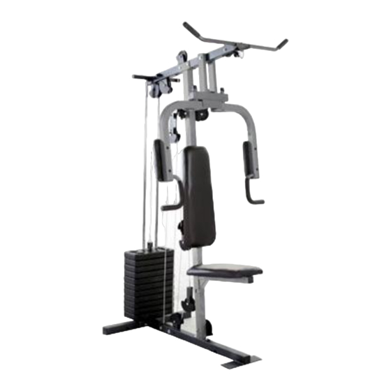
Weider 900 User Manual
Weight system exerciser
Hide thumbs
Also See for 900:
- Gebruikershandleiding (24 pages) ,
- Manuel de l'utilisateur (24 pages) ,
- Bedienungsanleitung (24 pages)
Table of Contents
Advertisement
Model No. WEEVSY1326.0
Serial No.
Write the serial number in the
space above for future reference.
Serial Number Decal (Under Seat)
QUESTIONS?
As a manufacturer, we are com-
mitted to providing complete
customer satisfaction. If you
have questions, or if there are
missing parts, please call:
08457 089 009
Or write:
ICON Health & Fitness, Ltd.
Unit 4
Revie Road Industrial Estate
Revie Road
Beeston
Leeds, LS118JG
UK
email: csuk@iconeurope.com
CAUTION
Read all precautions and instruc-
tions in this manual before using
this equipment. Save this manual
for future reference.
USER'S MANUAL
Visit our website at
www.iconeurope.com
Advertisement
Table of Contents

Related Manuals for Weider 900


Summary of Contents for Weider 900
- Page 1 Model No. WEEVSY1326.0 Serial No. USER'S MANUAL Write the serial number in the space above for future reference. Serial Number Decal (Under Seat) QUESTIONS? As a manufacturer, we are com- mitted to providing complete customer satisfaction. If you have questions, or if there are missing parts, please call: 08457 089 009 Or write:...
-
Page 2: Table Of Contents
Apply the decal in the location shown. VERTICAL WARNING PN 218558 – Black Text/Clear Background PN 218559 – White Text/Clear Background WEIDER is a registered trademark of ICON IP, Inc. -
Page 3: Important Precautions
IMPORTANT PRECAUTIONS WARNING: To reduce the risk of serious injury, read the following important precau- tions before using the weight system. 1. Read all instructions in this manual and in 6. Inspect and properly tighten all parts regular- the accompanying literature and all warnings ly. -
Page 4: Before You Begin
BEFORE YOU BEGIN Thank you for selecting the versatile WEIDER ® al. To help us assist you, please note the product weight system. The weight system offers a selection of model number and serial number before contacting us. weight stations designed to develop every major mus- The model number is WEEVSY1326.0. -
Page 5: Part Identification Chart
PART IDENTIFICATION CHART M6 x 16mm M6 x 63mm Screw (67) M8 x 63mm Bolt (66) Screw (40) M6 x 58mm Screw (65) M8 x 63mm Carriage Bolt (58) M6 Washer (73) M10 x 52mm Bolt (52) M10 x 65mm Carriage Bolt (59) M10 x 46mm Bolt (53) M8 Washer (71) M8 x 70mm Carriage Bolt (56) -
Page 6: Part Identification Chart
ASSEMBLY • As you assemble the weight system, make sure Make Things Easier for Yourself all parts are oriented as shown in the drawings. Everything in this manual is designed to ensure • For help identifying small parts, use the PART that the weight system can be assembled suc- IDENTIFICATION CHART. - Page 7 2. Attach the Upright (3) to the Base (1) with the two M8 x 63mm Carriage Bolts (58) and two M8 Nylon Locknuts (69). Do not tighten the Nylon Locknuts yet. Attach the Press Frame Lock (39) to the Upright (3) with an M8 x 63mm Bolt (66), two M8 Washers (71), and an M8 Nylon Locknut (69).
- Page 8 4. Slide eight Weights (15) onto the Weight Guides (10), with the slot for the Weight Pin (not shown) on the bottom and on the side fac- ing away from the Upright (3). Lubricate Insert the Weight Tube (12) into the Weights (15).
-
Page 9: M6 Nylon
ARM ASSEMBLY 7. Apply grease to an M10 x 125mm Bolt (64). Grease Orient the Press Frame (5) with the bracket on the side shown. Attach the Press Frame to the Top Frame (4) with the Bolt, two M10 Washers (70), and an M10 Nylon Locknut (68). - Page 10 CABLE ASSEMBLY 10. See the CABLE DIAGRAM on page 18 for proper cable routing. Identify the High Cable (50). Route the threaded shaft end of the Cable up through the Top Frame (4) and over a 90mm Pulley (34). Attach the Pulley inside the Top Frame with an M10 x 65mm Bolt (55), two M10 Washers (70), two Small Spacers (37), and an M10 Nylon Locknut (68).
-
Page 11: M8 Nylon
14. Attach the end of the High Cable (50) to the Small “U”-bracket (11) with an M8 Washer (71) and an M8 Nylon Locknut (69). Note: Do not completely tighten the Nylon Locknut; it should be threaded onto the Cable so that two threads show past the Nylon Locknut, as shown in the inset drawing. - Page 12 18. Apply grease to an M10 x 78mm Bolt (54). Attach a Pulley Arm (38) to the Upright (3) with Grease the Bolt and an M10 Nylon Locknut (68). Do not overtighten the Nylon Locknut; the Pulley Arm must pivot easily. Route the Press Cable (49) over a 90mm Pulley (34).
- Page 13 21. Route the Short Cable (47) over a 90mm Pulley (34). Attach the Pulley and two Finger Guards (35) to the Double “U”-bracket (42) with an M10 x 46mm Bolt (53) and an M10 Nylon Locknut (68). 22. Attach the end of the Short Cable (47) to the “U”-bracket (43) with an M8 Washer (71) and an M8 Nylon Locknut (69).
- Page 14 25. Route the Low Cable (48) under a 90mm Pulley (34). Attach the Pulley and two Finger Guards (35) to the bracket on the Base (1) with an M10 x 46mm Bolt (53) and an M10 Nylon Locknut (68). 26. Route the Low Cable (48) over a 90mm Pulley (34).
- Page 15 SEAT ASSEMBLY 28. Attach the Backrest (18) to the Upright (3) with two M6 x 63mm Screws (67) and two M6 Washers (73). Wide End 29. Orient the Seat (19) as shown, and attach it to the Seat Frame (8) with four M6 x 16mm Screws (40).
-
Page 16: Adjustment
ADJUSTMENT This section explains how to adjust the weight system. Refer to the accompanying exercise guide to see the cor- rect form for each exercise. Make sure all parts are properly tightened each time you use the weight system. Replace any worn parts immediate- ly. -
Page 17: Weight Resistance Chart
WEIGHT RESISTANCE CHART The chart below shows the approximate weight resistance at each exercise station. Weight resistance shown for the butterfly arm station is for each butterfly arm. Note: The actual resistance at each station may vary due to differences in individual weight plates as well as friction between the cables, pulleys, and weight guides. -
Page 18: Cable Diagram
CABLE DIAGRAM The cable diagram below shows the proper routing of the Short Cable (47), the Low Cable (48), the Press Cable (49), and the High Cable (50). Use the diagrams to make sure that the cables have been assembled cor- rectly. -
Page 19: Troubleshooting And Maintenance
TROUBLESHOOTING AND MAINTENANCE TIGHTENING THE CABLES Woven cable, the type of cable used on the weight system, can stretch slightly when it is first used. If there is slack in the cables before resistance is felt, the cables should be tightened. Slack can be removed by moving a 90mm Pulley (34), a Cable Trap (36), and two Finger Guards (35) to a set of holes closer to the center of the two Pulley... - Page 20 NOTES...
-
Page 21: Part List
PART LIST—Model No. WEEVSY1326.0 R0906A Key No. Qty. Description Key No. Qty. Description Base M6 x 16mm Screw Stabilizer 50mm Square Outer Cap Upright Double “U”-bracket Top Frame “U”-bracket Press Frame Pulley Plate Right Arm Butterfly Grip Left Arm M10 x 100mm Bolt Seat Frame Short Cable Chain... -
Page 22: Exploded Drawing
EXPLODED DRAWING A—Model No. WEEVSY1326.0 R0906A... - Page 23 EXPLODED DRAWING B—Model No. WEEVSY1326.0 R0906A 73 67...
-
Page 24: Ordering Replacement Parts
Please provide the following information when ordering replacement parts: • the MODEL NUMBER of the product (WEEVSY1326.0) • the NAME of the product (WEIDER 900 weight system) • the SERIAL NUMBER of the product (see the front cover of this manual) •...