Weider Wedier Pro 9635 User Manual
Canadian english manual
Hide thumbs
Also See for Wedier Pro 9635:
- User manual (33 pages) ,
- Manual (20 pages) ,
- Manuel de l'utilisateur (34 pages)
Table of Contents
Advertisement
Model No. WESY9635C.3
Serial No.
Write the serial number in the space
above for reference.
Serial Number Decal (under seat)
QUESTIONS?
As a manufacturer, we are
committed to providing com-
plete customer satisfaction. If
you have questions, or if
there are missing parts,
please call:
1-888-936-4266
Mon.–Fri. 8:00 until 17:00
EST (excluding holidays).
CAUTION
Read all precautions and instruc-
tions in this manual before using
this equipment. Save this manual
for future reference.
USER'S MANUAL
Visit our website at
www.proform.com
Visit our website at
www.healthrider.com
Visit our website at
www.nordictrack.com
Visit our website at
www.weiderfitness.com
Visit our website at
Advertisement
Table of Contents

Related Manuals for Weider Wedier Pro 9635


Summary of Contents for Weider Wedier Pro 9635
- Page 1 Model No. WESY9635C.3 Serial No. USER’S MANUAL Write the serial number in the space above for reference. Serial Number Decal (under seat) QUESTIONS? As a manufacturer, we are committed to providing com- plete customer satisfaction. If you have questions, or if there are missing parts, please call: 1-888-936-4266...
-
Page 2: Table Of Contents
The decals shown here have been placed on the weight system. If a decal is missing or illegible, please call the toll-free telephone number on the front cover of this manual and order a free replacement decal. Apply the decal in the location shown. Part # 152138 WEIDER is a registered trademark of ICON IP, Inc. -
Page 3: Important Precautions
IMPORTANT PRECAUTIONS WARNING: To reduce the risk of serious injury, read the following important precautions before using the weight system. 1. Read all instructions in this manual and in 10. Always wear athletic shoes for foot protec- the accompanying literature, and all warn- tion. -
Page 4: Before You Begin
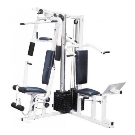
BEFORE YOU BEGIN Thank you for selecting the versatile WEIDER ® reading this manual, see the front cover of this manu- 9635 weight system. The weight system offers a selec- al. To help us assist you, please note the product tion of weight stations designed to develop every model number and serial number before calling. -
Page 5: Assembly
ASSEMBLY • As you assemble the weight system, make sure Make Things Easier for Yourself all parts are oriented as shown in the drawings. Everything in this manual is designed to ensure • Assembly requires two people. that the weight system can be assembled suc- cessfully by almost anyone. - Page 6 2. Slide the VKR Upright (74) and the Leg Press Upright (56) onto the indicated M8 x 62mm Carriage Bolts (1) in the Stabilizer (5). The high side of the brackets on the VKR Upright and Leg Press Upright should be on the side shown.
- Page 7 4. Attach the Top Frame (55) to the VKR Upright (74) and the Leg Press Upright (56) with two M8 x 67mm Bolts (11) and two M8 Nylon Locknuts (3). Attach the Top Frame (55) to the Front Upright (42) with two M8 x 67mm Bolts (11), two M8 Washers (8), and two M8 Nylon Locknuts (3).
- Page 8 7. Press a Weight Tube Bumper (64) into the end of a Weight Tube (63). Insert the Weight Holes Tube into the front stack of Weights (25). Make sure that the pin on the Weight Tube is sitting in the pin groove in the top Weight.
- Page 9 9. Attach the upper ends of the Short Weight Guides (73) to the Top Frame (55) with an M8 x 150mm Bolt (60), two 13mm x 19mm Spacers (61), and an M8 Nylon Locknut (3). Attach the upper ends of the Long Weight Guides (62) to the Top Frame (55) with an M8 x 150mm Bolt (60), two 13mm x 19mm Spacers (61), and an M8 Nylon Locknut (3).
- Page 10 12. Attach the Press Arm (46) to one side of the Press Frame (17) with two M8 x 63mm Bolts (22) and two M8 Nylon Locknuts (3). Assemble the other Press Arm (46) in the same manner. 13. Identify the Right Arm (48) and the Left Arm (47).
-
Page 11: Cable Assembly
15. See the inset drawing. Attach the Military Press Arm (84) to the Pivot Arm (101) with two M8 x 57mm Bolts (33) and two M8 Nylon Locknuts (3). Attach the Pivot Arm (101) to the VKR Upright (74) with an M10 x 83mm Bolt (67) and an M10 Nylon Locknut (21). - Page 12 18. Wrap the High Cable (58) around a “V”-pulley (50). Attach the “V”-pulley and a Long Cable Trap (31) to the indicated bracket on the Front Upright (42) with an M10 x 57mm Bolt (86) and an M10 Nylon Locknut (21). Make sure that the Long Cable Trap is positioned to hold the Cable in place.
- Page 13 22. See the inset drawing. Route the High Cable (58) under a 90mm Pulley (15). Attach the Pulley and a Cable Trap (66) to the upper hole in a Long “U”-bracket (57) with an M10 x 47mm Bolt (12) and an M10 Nylon Locknut (21).
- Page 14 25. Route the Low Cable (23) under a 90mm Pulley (15). Attach the Pulley and a Cable Trap (66) to the lower hole in the Front Upright (42) with an M10 x 92mm Bolt (88), an M10 Washer (9), and an M10 Nylon Locknut (21).
- Page 15 28. Attach the end of the Low Cable (23) to the Long “U”-bracket (57) with an M8 Nylon Locknut (3) and an M8 Washer (8). Do not completely tighten the Locknut. It should be threaded onto the end of the Cable so that only two threads are showing past the Locknut, as shown in the inset drawing.
- Page 16 31. Wrap the Military Press Cable (72) over a 90mm Pulley (15). Attach the Pulley to the Top Frame (55) with an M10 x 47mm Bolt (12) and an M10 Nylon Locknut (21). See the inset drawing. Wrap the Military Press Cable (72) under a 90mm Pulley (15).
- Page 17 33. See inset drawing A. Route the Military Press Cable (72) under a 90mm Pulley (15). Attach the Pulley and a Cable Trap (66) to the upper hole in the Long “U”-bracket (57) with an M10 x 47mm Bolt (12) and an M10 Nylon Locknut (21).
- Page 18 35. Attach the Press Bracket (94) to the Leg Press Arm (96) with an M10 x 78mm Bolt (105) and an M10 Nylon Locknut (21). Wrap the Leg Press Cable (99) around a 90mm Pulley (15). Attach the Pulley to the Press Bracket (94) with the M10 x 47mm Bolt (12) and an M10 Nylon Locknut (21).
- Page 19 38. Orient the Front Backrest (41) as shown. Attach the Backrest to the Front Upright (42) with two M6 x 63mm Screws (43) and two M6 Washers (10). Thick 39. Insert an M6 x 50mm Carriage Bolt (38) through the center hole in the Seat Plate (37). Attach the Seat Plate to the Seat (13) with two M6 x 16mm Screws (18).
- Page 20 42. Insert a Pad Tube (28) into the Front Seat Frame (36). Slide a Foam Pad (30) onto each end of the Pad Tube. Insert the other Pad Tube (28) into the Leg Lever (29). Slide a Foam Pad (30) onto each end of the Pad Tube.
-
Page 21: How To Use The Weight System
45. Make sure that all parts have been properly tightened. The use of the remaining parts will be explained in HOW TO USE THE WEIGHT SYSTEM, beginning on page 22 of this manual. Before using the weight system, pull each cable a few times to be sure that the cables move smoothly over the pulleys. - Page 22 HOW TO USE THE WEIGHT SYSTEM The instructions below describe how each part of the weight system can be adjusted. Refer to the exercise poster accompanying this manual to see how the weight system should be set up for each exercise. IMPOR- TANT: When attaching the lat bar or nylon strap, make sure that the attachments are in the correct start- ing position for the exercise to be performed.
- Page 23 ATTACHING AND REMOVING THE SEAT To attach the Seat (13), set the bracket on the Front Seat Frame (36) onto the indicated pins on the Front Upright (42). Attach the Seat Frame to the Front Upright with the M8 x 70mm Carriage Bolt (14) and the Seat Knob (40).
-
Page 24: Weight Resistance Chart
WEIGHT RESISTANCE CHART This chart shows the approximate weight resistance at each weight station. “Top” refers to the 6.5 lb. (2.9 kg) top weight. The other numbers refer to the 12.5 lb. (5.7 kg) weight plates. The butterfly arm resistance listed is the resistance for each butterfly arm. -
Page 25: Troubleshooting And Maintenance
TROUBLESHOOTING AND MAINTENANCE Inspect and tighten all parts each time you use the weight system. Replace any worn parts immediately. The weight system can be cleaned using a damp cloth and mild non-abrasive detergent. Do not use solvents. TIGHTENING THE CABLES Woven cable, the type of cable used on the weight system, can stretch slightly when it is first used. -
Page 26: Cable Diagrams
CABLE DIAGRAMS The cable diagrams on these pages show the proper routing of the High Cable (58), the Low Cable (23), the Military Press Cable (72), and the Leg Press Cable (99). Use the diagrams to be sure that the four cables and the cable traps have been assembled correctly. - Page 27 Military Press Cable (72) and Leg Press Cable (99) Military Press Cable (72) 6—Pivot Arm 1—Long “U”-bracket Rear Weight Stack—1 4—Rear Seat Frame Leg Press Cable (99)
- Page 28 1. the MODEL NUMBER of the product (WESY9635C.3) 2. the NAME of the product (WEIDER PRO 9635 weight system) 3. the SERIAL NUMBER of the product (see the front cover of this manual) 4. the KEY NUMBER and DESCRIPTION of the part(s) (see the PART LIST and EXPLODED DRAWING...
- Page 30 M8 x 67mm Bolt (11) M8 x 70mm Carriage Bolt (14) M8 x 63mm Bolt (22) M8 x 70mm Bolt (75) M6 x 63mm Screw (43) M8 x 74mm Shoulder Bolt (103) M6 x 63mm Carriage Bolt (92) M10 x 78mm Bolt (105) M10 x 83mm Bolt (67) M10 x 90mm Bolt (16) M10 x 92mm Bolt (88)
- Page 31 PART IDENTIFICATION CHART R0605B M4 x 16mm Self-tapping Screw (87) M6 Nylon Locknut (2) M6 x 16mm Screw (18) M8 Nylon Locknut (3) M8 x 45mm Bolt (24) M10 Nylon Locknut (21) M10 x 47mm Bolt (12) M4 Washer (76) M6 x 50mm Screw (81) M6 x 50mm Carriage Bolt (38) M6 Washer (10)
- Page 32 SAVE THIS PART LIST/EXPLODED DRAWING FOR FUTURE REFERENCE...
- Page 33 PART LIST—Model No. WESY9635C.3 R0605B Key No. Qty. Description Key No. Qty. Description M8 x 62mm Carriage Bolt Top Frame M6 Nylon Locknut Leg Press Upright M8 Nylon Locknut Long “U”-bracket Base High Cable Stabilizer M10 x 196mm Bolt 25mm Square Inner Cap M8 x 150mm Bolt 16mm x 14mm Spacer 13mm x 19mm Spacer...