Table of Contents
Advertisement
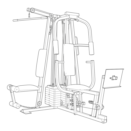
Model No. WESY41080
Serial No.
Write the serial number in the space
above for future reference.
Serial Number Decal (Under Seat)
QUESTIONS?
As a manufacturer, we are
committed to providing complete
customer satisfaction. If you
have questions, or if there are
missing or damaged parts, we
will guarantee complete satisfac-
tion through direct assistance
from our factory.
TO AVOID UNNECESSARY
DELAYS, PLEASE CALL DIRECT
TO OUR TOLL-FREE CUSTOMER
HOT LINE. The trained techni-
cians on our customer hot line
will provide immediate assis-
tance, free of charge to you.
CUSTOMER HOT LINE:
1-800-999-3756
Mon.ÐFri., 6 a.m.Ð6 p.m. MST
CAUTION
Read all precautions and instruc-
tions in this manual before using
this equipment. Save this manual
for future reference.
USERÕS
MANUAL
PATENT PENDING
Advertisement
Table of Contents

Related Manuals for Weider WESY41080


Summary of Contents for Weider WESY41080
- Page 1 Model No. WESY41080 Serial No. Write the serial number in the space above for future reference. Serial Number Decal (Under Seat) QUESTIONS? As a manufacturer, we are committed to providing complete customer satisfaction. If you have questions, or if there are...
-
Page 2: Table Of Contents
Table of Contents Important Precautions ..............2 Before You Begin . -
Page 3: Before You Begin
Mountain Time (excluding holidays). To help us assist you, please note the product model number and serial number before calling. The model number is WESY41080. The serial number can be found on a decal attached to the WEIDER PRO front cover of this manual). -
Page 4: Assembly
Assembly Note: This introduction will save you more time than it takes to read it! Making Things Easier for Yourself Everything in this manual is designed to ensure that the assembly of our products can be complet- ed successfully by anyone. However, it is impor- tant to recognize that your new equipment is a sophisticated product with many small parts. -
Page 5: Frame Assembly
Frame Assembly 1. Before beginning assembly, make sure you have read and understand the information in the box above. Locate and open the parts bags labeled ÒFRAME ASSEMBLY BAG ONEÓ and ÒFRAME ASSEMBLY BAG TWO.Ó Press a 2Ó Square Outer Cap (58) onto the indicated end of the Weight Base (14). - Page 6 3. Press a 2Ó Square Inner Cap (56) into the end of the Top Frame (2). Press a 2Ó Square Inner Cap (56) into each side of the Butterfly Frame (3). Press two 1Ó Round Inner Caps (70) into the top of the Butterfly Frame.
- Page 7 5. Insert two Weight Guides (23) into each of the brack- ets on the Weight Base (14). Slide a Weight Bumper (27) onto each of the Weight Guides (23). Slide eight Weights (90) onto each set of Weight Guides (23). Make sure the pin grooves are on the indicated side of each stack of Weights.
- Page 8 7. Lubricate the insides of the holes in the Top Weights (24) as shown. Slide a Top Weight onto each set of Weight Guides (23). 8. Attach the Top Frame (2) to the Lat Upright (1) with two 5/16Ó x 2 3/4Ó Bolts (55), two 5/16Ó Washers (20) and two 5/16Ó...
-
Page 9: Arm Assembly
10. Press a 2Ó Square Inner Cap (56) into each end of the Leg Press Arm (9). Arm Assembly 11. Locate and open the parts bag labeled ÒARM ASSEMBLY.Ó Attach the Leg Press Bumper (53) to the Front Seat Frame (8) with the 1Ó Tap Screw (72). Lubricate the 3/8Ó... - Page 10 13. Attach a Press Arm (7) to one side of the Press Frame (12) with two 5/16Ó x 2 1/2Ó Bolts (39) and two 5/16Ó Nylon Locknuts (40). Attach the other Press Arm (7) to the Press Frame (12) in the same manner. 14.
-
Page 11: Cable Assembly
16. Press a 1 3/4Ó Square Inner Cap (48) into the lower end of the Left Arm (6). Wet the lower end of the Left Arm with soapy water. Slide a 10Ó Pad (45) onto the Left Arm. Repeat this step with the Right Arm (5). Note: The remaining parts from the parts bag labeled ÒARM ASSEMBLYÓ... - Page 12 19. Wrap the Butterfly Cable (89) around a 3 1/2Ó Pulley (82) as shown. Attach the Pulley and a Cable Trap (80) to the bracket on the Leg Press Upright (4) with a 3/8Ó x 2Ó Bolt (50) and a 3/8Ó Nylon Locknut (42). The Cable Trap must be oriented as shown and be positioned to hold the Cable in the groove of the Pulley.
- Page 13 23. Find the Rear Cable (87)Ñthis is the shortest Cable. Slide one end of the Rear Cable onto the 5/16Ó x 3Ó Bolt (92). Thread another 5/16Ó Nylon Jam Nut (91) onto the Bolt, but do not fully tighten it. Leave enough room between the two Jam Nuts for the Cable to pivot.
- Page 14 27. Find the Press Cable (88)Ñthis is the longest Cable. Attach the end of the Press Cable (88) to the Large ÒUÓ Bracket (84) with a 1/4Ó Nylon Locknut (44) and a 1/4Ó Washer (37). Do not completely tighten the Nylon Locknut. It should be threaded onto the end of the Cable so only a couple of threads are showing above the Nylon Locknut, as shown in the inset drawing.
- Page 15 30. Route the Press Cable (88) over the indicated 3 1/2Ó Pulley (82) attached to the Pulley Plates (31). The Cable must be routed from the direction shown. Refer to the inset drawing. Make sure the Cable is between the Cable Trap (80) and the Pulley. Make sure the Cable Trap is positioned to hold the Cable in place as shown in the inset drawing.
- Page 16 34. Route the Press Cable (88) around a 3 1/2Ó Pulley (82). Attach the Pulley and a Cable Trap (80) to the Press Frame (12) with a 3/8Ó x 3Ó Bolt (94), a 3/8Ó Washer (38) and a 3/8Ó Nylon Jamnut (43). Make sure the Cable Trap (80) is turned to hold the Cable in place and that the Cable is between the Pulley and the crossbar on the Press Frame.
- Page 17 38. Note: The 3 1/2Ó Pulley (82) used in this step was attached in step 36. It is shown removed for easier part identification. Route the Press Cable (88) around the 3 1/2Ó Pulley (82). Make sure the Cable Trap (80) is turned to hold the Cable in place and that the Cable is rout- ed as shown.
- Page 18 42. Locate the remaining preassembled pair of Pulley Plates (31) and 3 1/2Ó Pulleys (82). Route the High Cable (85) under the indicated 3 1/2Ó Pulley (82). The end of the Pulley Plates (31) with two holes should be downward. Refer to the inset draw- ing.
- Page 19 46. Remove the indicated 3/8Ó x 2Ó Bolt (50), the 3/8Ó Nylon Locknut (42), the 3 1/2Ó Pulley (82) and the Cable Trap (80) from the indicated Pulley Plates (31). Lay the Low Cable (86) over the Pulley. Re-attach the Pulley and the Cable Trap to the lowest hole in the Pulley Plates with the Bolt and the Nylon Locknut.
-
Page 20: Seat Assembly
Seat Assembly 48. Locate and open the parts bag labeled ÒSEAT ASSEMBLY.Ó Attach a Small Backrest (97) to the Lat Upright (1) with two 1/4Ó x 2 1/2Ó Machine Screws (64) and two 1/4Ó Washers (37). 49. Press a 1 1/2Ó Square Inner Cap (57) into the Rear Seat Frame (16). - Page 21 52. Press two 3/4Ó Round Inner Caps (78) into each Pad Tube (28). Insert a Pad Tube (28) into the Rear Seat Frame (16). Slide a Foam Pad (29) onto each end of the Pad Tube. Insert the other Pad Tube (28) into the Leg Lever (15). Slide a Foam Pad (29) onto each end of the Pad Tube.
- Page 22 56. Attach the Left (18) and the Right (32) VKR Arm to the VKR Upright (51) with two 5/16Ó x 3Ó Bolts (92) and two 5/16Ó Nylon Locknuts (40). 57. Attach the VKR Backrest (76) to the VKR Upright (51) with two 1/4Ó...
-
Page 23: How To Use The Home Gym System
How to Use the Home Gym System The instructions below describe how each part of the home gym system can be adjusted. Refer to the exercise poster accompanying this manual to see how the home gym system should be set up for each exercise. IMPORTANT: When attaching the lat bar or handle, make sure that the attachments are in the correct starting position for the exercise to be performed. - Page 24 ATTACHING AND REMOVING THE SEAT To attach the Seat (17), set the bracket on the Rear Seat Frame (16) onto the pins on the Lat Upright (1). Attach the Rear Seat Frame to the Lat Upright with the 5/16Ó x 2 3/4Ó Carriage Bolt (77) and the Seat Knob (30).
-
Page 25: Trouble-Shooting And Maintenance
Trouble-shooting and Maintenance Inspect and tighten all parts each time you use the home gym system. Replace any worn parts immediately. The home gym system can be cleaned using a damp cloth and mild non-abrasive detergent. Do not use solvents. TIGHTENING THE CABLES Woven cable, the type of cable used on the home gym system, can stretch slightly when it is first used. -
Page 26: Cable Diagrams
Cable Diagrams The cable diagrams on this page and the next page show the proper routing of the High Cable (85), the Low Cable (86), the Rear Cable (87), the Press Cable (88), and the Butterfly Cable (89). Use the diagrams to be sure that the Cables have been assembled correctly. -
Page 27: Weight Resistance Chart
High Cable (85) High PulleyÑ1 Weight StackÑ5 Weight Resistance Chart This chart shows the approximate weight resistance at each station. ÒTopÓ refers to the 6.5 lbs. top weight. The other numbers refer to the 12.5 lbs. weight plates. Note: The actual resistance at each weight station may vary due to differences in individual weight plates, as well as friction between the cables, pulleys, and weight guides. - Page 29 Part List - Model No. WESY41080 Key No. Qty. Description Lat Upright Top Frame Butterfly Frame Leg Press Upright Right Fly Arm Left Fly Arm Press Arm Front Seat Frame Leg Press Arm 1 1/4Ó x 1/2Ó Weight Spacer Leg Press Plate...
- Page 30 1/4" x 2" Machine Screw (63) 1/4" x 2" Carriage Bolt (61) 1/4" x 2 1/2" Machine Screw (64) 1/4" x 2 1/2" Carriage Bolt (60) 5/16" x 2 1/2" Carriage Bolt (49) 5/16" x 2 3/4" Carriage Bolt (77) 5/16"...
- Page 31 1/4" Washer (37) 5/16" Washer (20) 5/16" x 1" Bolt (95) 1" Retainer (45) 3/8" x 2" Bolt (50) 3/8" Washer (38) 1/2" Plain Nut (35) 5/16" x 2 1/4" Bolt (62) 1/4" Nylon Locknut (44) 5/16" x 2 1/2" Bolt (39) 5/16"...
- Page 32 1" x 7/8" Plastic Bushing (54) 1 1/4" x 1/2Ó Spacer (10) 1" Round Inner Cap (70) 1 1/8" x 2 1/2" Plastic Bushing (47) 1 1/2" Square Inner Cap (57) 1/2" x 3/4" Spacer (69) 1" Round Outer Cap (46) 3/4"...
-
Page 33: Ordering Replacement Parts
Friday, 6 a.m. until 6 p.m. Mountain Time (excluding holidays). To help us assist you, please be pre- pared to give the following information: 1. The MODEL NUMBER of the product (WESY41080). 2. The NAME of the product (WEIDER PRO 3.