KTM 200 DUKE EU Owner's Manual
2012
Hide thumbs
Also See for 200 DUKE EU:
- Repair manual (267 pages) ,
- Owner's manual (198 pages) ,
- Installation instructions manual (17 pages)
Table of Contents
Advertisement
Quick Links
Advertisement
Table of Contents

Related Manuals for KTM 200 DUKE EU


Summary of Contents for KTM 200 DUKE EU
- Page 1 OWNER'S MANUAL 2012 125 Duke EU 125 Duke DE 200 Duke EU Art. no. 3211800en...
- Page 3 KTM accepts no liability for delivery options, deviations from illustrations and descriptions, as well as misprints and other errors.
- Page 4 Reproduction, even in part, as well as copying of all kinds, is permitted only with the express written permission of the copyright owner. ISO 9001(12 100 6061) According to the international quality management standard ISO 9001, KTM uses quality assurance processes that lead to the maximum possible quality of the products.
-
Page 5: Table Of Contents
TABLE OF CONTENTS Combination instrument - warning notes ......32 TABLE OF CONTENTS MEANS OF REPRESENTATION ..........6 Riding time/average speed menu........34 IMPORTANT INFORMATION ........... 7 Average speed/average fuel consumption 1 menu ....35 VIEW OF VEHICLE..............12 Average fuel consumption 1/average fuel consumption 2 View of vehicle, front left (example)........ - Page 6 TABLE OF CONTENTS RIDING INSTRUCTIONS ............54 BRAKES ................84 Checks and maintenance when preparing for use....54 Checking the brake discs........... 84 Starting ................55 Checking the brake fluid level of the front brake ....84 Starting off ..............56 Adding front brake fluid ..........
- Page 7 TABLE OF CONTENTS COOLING SYSTEM ............. 119 TECHNICAL DATA - CHASSIS ..........149 Cooling system ............... 119 Lighting equipment ............150 Checking the antifreeze and coolant level ......120 Tires ................151 Checking the coolant level..........122 Capacity - fuel..............151 TECHNICAL DATA - FORK...........
-
Page 8: Means Of Representation
All work marked with this symbol requires specialist knowledge and technical understanding. In the interest of your own safety, have these jobs performed by an authorized KTM workshop! There, your motorcycle will be serviced opti- mally by specially trained experts using the specialist tools required. -
Page 9: Important Information
IMPORTANT INFORMATION Use definition KTM sport motorcycles are designed and constructed to meet the normal demands of regular road operation but not for use on race courses or offroad. Info The motorcycle is authorized for public road traffic in the homologous version only. - Page 10 Spare parts, accessories For your own safety, only use spare parts and accessory products that have been approved and/or recommended by KTM and have them installed by an authorized KTM workshop. KTM accepts no liability for other products and any resulting damage.
- Page 11 IMPORTANT INFORMATION – Use straps or other suitable devices to secure the motorcycle against falling over and rolling away. Environment If you use your motorcycle responsibly, you can ensure that problems and conflicts do not occur. To protect the future of the motorcycle sport, make sure that you use your motorcycle legally, display environmental consciousness, and respect the rights of others.
- Page 12 IMPORTANT INFORMATION Grades of risks Danger Identifies a danger that will immediately and invariably lead to fatal or serious permanent injury if the appropriate measures are not taken. Warning Identifies a danger that is likely to lead to fatal or serious injury if the appropriate measures are not taken. Caution Identifies a danger that may lead to minor injuries if the appropriate measures are not taken.
-
Page 14: View Of Vehicle
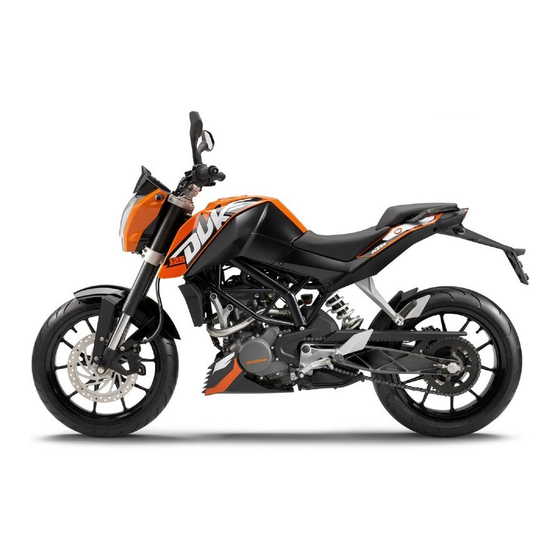
VIEW OF VEHICLE View of vehicle, front left (example) B00778-10... - Page 15 VIEW OF VEHICLE Combination instrument Rear mirror Clutch lever ( p. 18) Seat Passenger seat Seat lock ( p. 46) Grab handles ( p. 47) Engine number ( p. 16) Side stand ( p. 50) Shift lever ( p. 48)
-
Page 16: View Of Vehicle, Rear Right (Example)
VIEW OF VEHICLE View of vehicle, rear right (example) B00779-10... - Page 17 VIEW OF VEHICLE Tool set ( p. 47) Light switch ( p. 19) High beam flasher button ( p. 20) Turn signal switch ( p. 20) Horn button ( p. 21) Filler cap Ignition/steering lock ( p. 22) Emergency OFF switch ( p.
-
Page 18: Serial Numbers
SERIAL NUMBERS Chassis number/type label The chassis number is stamped on the right of the steering head. The type label is on the right of the frame behind the steering head. B00699-10 Engine number The engine number is stamped on the left side of the engine under the engine sprocket. B00700-10... -
Page 19: Key Number
SERIAL NUMBERS Key number The key number can be found on the KEYCODECARD. Info You need the key number to order a spare key. Keep the KEYCODECARD in a safe place. B00755-10... -
Page 20: Controls
CONTROLS Clutch lever The clutch lever is fitted on the left side of the handlebar. B00701-10 Hand brake lever The hand brake lever is fitted on the right side of the handlebar. The front brake is engaged using the hand brake lever. B00702-10... -
Page 21: Throttle Grip
CONTROLS Throttle grip The throttle grip is fitted on the right side of the handlebar. B00703-10 Light switch The light switch is fitted on the left side of the handlebar. Possible states Low beam on – Light switch is turned downward. In this position, the low beam and tail light are switched on. -
Page 22: High Beam Flasher Button
CONTROLS High beam flasher button The high beam flasher button is fitted on the left side of the handlebar. Possible states • High beam flasher button in neutral position High beam flasher button pressed – In this position, the headlight flasher (high beam) •... -
Page 23: Horn Button
CONTROLS Horn button The horn button is fitted on the left side of the handlebar. Possible states • Horn button in neutral position pressed – The horn is operated in this position. • Horn button B00706-11 Emergency OFF switch The emergency OFF switch is fitted on the right side of the handlebar. -
Page 24: Electric Starter Button
CONTROLS Electric starter button The electric starter button is fitted on the right side of the handlebar. Possible states • Electric starter button in basic position pressed – In this position, the electric starter is actuated. • Electric starter button B00708-10 Ignition/steering lock 5.10... -
Page 25: Combination Instrument - Overview
CONTROLS Combination instrument - overview 5.11 Combination instrument - display ( p. 27) Combination instrument - function buttons ( p. 25) Combination instrument - info display ( p. 31) Combination instrument - indicator lamps ( p. 26) 401289-10... -
Page 26: Combination Instrument - Activation And Test
CONTROLS Combination instrument - activation and test 5.12 Activation The combination instrument is activated when the ignition is switched on. Test The segments of the tachometer and the gear display light up and switch off in sequence. The speed display counts from 0 to 199 and back. The remaining display segments outside the info display light up briefly. -
Page 27: Combination Instrument - Function Buttons
CONTROLS Combination instrument - function buttons 5.13 You can change the display mode with the MODE button Possible display modes are total distance traveled (TRIP 1), distance 1 (ODO) and distance 2 (TRIP 2). Pressing and holding the SET button resets the distance 1 (TRIP 1) and distance 2 (TRIP 2) functions to 0.0 and briefly pressing the SET button changes the info... -
Page 28: Combination Instrument - Indicator Lamps
CONTROLS Combination instrument - indicator lamps 5.14 Possible states The turn signal indicator light flashes green simultaneously with the turn signals – Turn signal is switched on. The engine diagnosis warning lamp (MIL) lights up red – The OBD (onboard diagnosis) has identified an emissions- or safety-critical fault. -
Page 29: Combination Instrument - Display
CONTROLS Combination instrument - display 5.15 The speed is shown in kilometers per hour km/h or in miles per hour mph. The tachometer shows the engine speed in revolutions per minute. The gear display shows the engaged gear. The coolant temperature appears in segment The time appears in segment The filling level in the fuel tank is displaced in segment The info display... -
Page 30: Combination Instrument - Filling Level Display In Fuel Tank
CONTROLS Combination instrument - filling level display in fuel tank 5.16 The filling level display consists of 9 bars. The more bars are lit, the more fuel is in the fuel tank. 401292-01... -
Page 31: Combination Instrument - Trip F Display
CONTROLS Combination instrument - TRIP F display 5.17 If the fuel level drops to the reserve mark, the display mode automatically changes to TRIP F and starts to count from 0.0, regardless of the previous display mode. Info At the same time as the display mode TRIP F, the general warning lamp lights up and the warning note Low Fuel Level appears on the info display. -
Page 32: Combination Instrument - Coolant Temperature Indicator
CONTROLS Combination instrument - coolant temperature indicator 5.18 The temperature display consists of 13 bars. The more bars that light up, the hotter the coolant. When all bars light up, the following warning note appears on the info display: High Coolant Temperature. Possible states Engine cold –... -
Page 33: Combination Instrument - Info Display
CONTROLS Combination instrument - info display 5.19 Various warning notes appear on info display If the general warning lamp lights up, the corresponding warning note is shown on the info display. 401291-10... -
Page 34: Combination Instrument - Warning Notes
CONTROLS Combination instrument - warning notes 5.20 Low Oil Pressure appears on the info display if the oil pressure is too low. 401309-01 Low Fuel Level appears on the info display if the fuel level reaches the reserve mark. 401310-01... - Page 35 CONTROLS High Coolant Temperature appears on the info display if the coolant temperature rises above the specified value. Coolant temperature 125 °C (257 °F) 401311-01 Side Stand Down appears on the info display if the side stand is folded down. 401312-01 Low Battery appears on the info display if the battery voltage falls below the specified value.
-
Page 36: Riding Time/Average Speed Menu
CONTROLS Service Not Reset appears on the info display for 10 seconds when the ignition is switched on and the distance interval between service appointments has been exceeded or the service interval display was not reset during a service appointment. 401461-01 Riding time/average speed menu 5.21... -
Page 37: Average Speed/Average Fuel Consumption 1 Menu
CONTROLS Average speed/average fuel consumption 1 menu 5.22 Condition Alternative 1 • The ignition is on. • The motorcycle is stationary. Alternative 2 • The ignition is on. • The motorcycle is moving. – Press the SET button briefly and repeatedly until the desired info display appears. In this menu, the average speed and the average fuel consumption 1 are displayed in 401465-01 L/100 km (or L/100 miles). -
Page 38: Average Fuel Consumption 1/Average Fuel Consumption 2 Menu
CONTROLS Average fuel consumption 1/average fuel consumption 2 menu 5.23 Condition Alternative 1 • The ignition is on. • The motorcycle is stationary. Alternative 2 • The ignition is on. • The motorcycle is moving. – Press the SET button briefly and repeatedly until the desired info display appears. In this menu, the average fuel consumption 1 in L/100 km (or L/100 miles) and the aver- 401466-01 age fuel consumption 2 in km/L (or miles/L) are displayed. -
Page 39: Average Fuel Consumption 2/Service Menu
CONTROLS Average fuel consumption 2/service menu 5.24 Condition Alternative 1 • The ignition is on. • The motorcycle is stationary. Alternative 2 • The ignition is on. • The motorcycle is moving. – Press the SET button briefly and repeatedly until the desired info display appears. The average fuel consumption 2 in km/L (or miles/L) and the distance to the next service 401467-01 are displayed in this menu. -
Page 40: Service/Range Menu
CONTROLS Service/range menu 5.25 Condition Alternative 1 • The ignition is on. • The motorcycle is stationary. Alternative 2 • The ignition is on. • The motorcycle is moving. – Press the SET button briefly and repeatedly until the desired info display appears. This menu shows the distance to the next service and the range. -
Page 41: Range/Riding Time Menu
CONTROLS Range/riding time menu 5.26 Condition Alternative 1 • The ignition is on. • The motorcycle is stationary. Alternative 2 • The ignition is on. • The motorcycle is moving. – Press the SET button briefly and repeatedly until the desired info display appears. The range and the riding time are displayed in this menu. -
Page 42: Total Distance Menu Odo
CONTROLS Total distance menu ODO 5.27 Condition Alternative 1 • The ignition is on. • The motorcycle is stationary. Alternative 2 • The ignition is on. • The motorcycle is moving. – Press the MODE button briefly and repeatedly until ODO appears on the display. ODO shows the total distance covered. -
Page 43: Distance Menu 2 Trip 2
CONTROLS Press the SET button Display of TRIP 1 is reset for 5 - 10 seconds. Press the MODE but- Next display mode on the display ton. Distance menu 2 TRIP 2 5.29 Condition Alternative 1 • The ignition is on. •... -
Page 44: Setting The Time
CONTROLS The motorcycle is stationary. – Press the MODE button briefly and repeatedly until ODO appears on the display. – Press the MODE button for 5 - 10 seconds. The display changes from km/h to mph or from mph to km/h. 401303-01 Setting the time 5.31... -
Page 45: Adjusting The Shift Speed Rpm 1
CONTROLS Adjusting the shift speed RPM 1 5.32 Condition The ignition is on. The motorcycle is stationary. – Press the MODE button briefly and repeatedly until TRIP 2 appears on the display. – Press the MODE button for 5 - 10 seconds. The display RPM 1 appears. -
Page 46: Opening The Filler Cap
CONTROLS – Press the MODE button briefly and repeatedly until TRIP 2 appears on the display. – Press the SET button for 5 - 10 seconds. The display RPM 2 appears. Info The engine speed can be set at intervals of 50. RPM 2 is the engine speed above which the shift warning light lights up con- stantly. - Page 47 CONTROLS Warning Danger of poisoning Fuel is poisonous and a health hazard. – Avoid contact between fuel and skin, eyes and clothing. Do not inhale fuel vapors. If fuel gets into your eyes, rinse immediately with water and contact a doctor. Wash affected skin areas immediately with soap and water. If fuel is swallowed, contact a doc- tor immediately.
-
Page 48: Closing The Filler Cap
CONTROLS Closing the filler cap 5.35 Warning Fire hazard Fuel is highly flammable, poisonous and harmful to your health. – When closing the filler cap, ensure that it is closed correctly. Change cloth- ing that came into contact with fuel. Immediately clean skin that came into contact with fuel using soap and water. -
Page 49: Tool Set
CONTROLS Tool set 5.37 The tool set is located under the passenger seat. B00758-10 Grab handles 5.38 The grab handles are used for moving the motorcycle around. If you carry a passenger, the passenger can hold onto the grab handles during the trip. B00717-10... -
Page 50: Passenger Footrests
CONTROLS Passenger footrests 5.39 The passenger footrests can be folded in and out. Possible states Passenger footrests folded up – For operation without a passenger. • Passenger footrests folded down – For operation with a passenger. • B00713-01 Shift lever 5.40 Shift lever is mounted on the left side of the engine. -
Page 51: Foot Brake Lever
CONTROLS The gear positions can be seen in the photograph. The neutral or idle position is between the first and second gears. B00716-10 Foot brake lever 5.41 Foot brake lever is located in front of the right footrest. The foot brake lever is used to activate the rear brake. B00718-10... -
Page 52: Side Stand
CONTROLS Side stand 5.42 The side stand is on the left side of the vehicle. The side stand is used to park the motorcycle. Info The side stand must be folded up during motorcycle use. Side stand is coupled with the safety start system; see the riding instructions. Possible states Side stand folded out –... -
Page 53: Preparing For Use
The front and rear wheels must be fitted with tires with similar tread patterns to prevent loss of control over the vehicle. Warning Danger of accidents Uncontrollable handling characteristic due to non-approved and/or non-recommended tires/wheels. – Only tires/wheels approved by KTM and with the corresponding speed index should be used. Warning Danger of accidents Reduced road grip with new tires. –... -
Page 54: Running In The Engine
PREPARING FOR USE – Make sure that the pre-delivery inspection work has been carried out by an authorized KTM workshop. You receive a delivery certificate and the service record at vehicle handover. – Before your first trip, read the entire operating instructions carefully. - Page 55 PREPARING FOR USE Warning Danger of accidents Unstable handling characteristics due to incorrect mounting of suitcase and/or tank rucksack. – Mount and secure suitcase and tank rucksack according to the manufacturer's instructions. Warning Danger of accidents Risk of breakage of suitcase system. –...
-
Page 56: Riding Instructions
RIDING INSTRUCTIONS Checks and maintenance when preparing for use Info Before every trip, check the condition of the vehicle and ensure that it is roadworthy. The vehicle must be in perfect technical condition when used. – Check the engine oil level. ( p. -
Page 57: Starting
RIDING INSTRUCTIONS Starting Danger Danger of poisoning Exhaust gases are poisonous and inhaling them may result in unconsciousness and/or death. – When running the engine, always make sure there is sufficient ventilation, and do not start or run the engine in an enclosed space without an effective exhaust extraction system. -
Page 58: Starting Off
RIDING INSTRUCTIONS – Sit on the vehicle, take the weight off of the side stand, and move up all the way. – Turn the emergency OFF switch to the position – Switch on the ignition by turning the ignition key to the position After you switch on the ignition, you can hear the fuel pump working for about two seconds. -
Page 59: Shifting, Riding
RIDING INSTRUCTIONS Shifting, riding Warning Danger of accidents Abrupt load alterations can cause the vehicle to get out of control. – Avoid abrupt load alterations and sudden braking actions, and adapt your speed to the road conditions. Warning Danger of accidents If you change down at high engine speed, the rear wheel can lock up. –... - Page 60 If you continue with the coolant temperature warning lamp alight, you may have engine failure. Info If you hear unusual noises while riding, stop immediately, switch off the engine and contact an authorized KTM workshop.
-
Page 61: Applying The Brakes
Switch off the engine if you expect to be standing for a long time. – If the engine diagnosis warning lamp lights up during a trip, stop immediately, switch off the engine, and contact an authorized KTM workshop. Applying the brakes Warning Danger of accidents If you brake too hard, the wheels can lock. -
Page 62: Stopping, Parking
Danger of accidents Reduced braking efficiency caused by spongy pressure point of front or rear brake. – Check the brake system and do not continue riding. (Your authorized KTM workshop will be glad to help.) Warning Danger of accidents Longer stopping distance due to higher overall weight. - Page 63 RIDING INSTRUCTIONS Warning Danger of burns Some vehicle components become very hot when the vehicle is operated. – Do not touch hot components such as exhaust system, radiator, engine, shock absorber and brakes. Allow these components to cool down before starting work on them. Note Danger of damage The parked vehicle may roll away or fall over.
-
Page 64: Refueling
– In some countries and regions, the available fuel quality and cleanliness may not be sufficient. This will result in problems with the fuel system. (Your authorized KTM workshop will be glad to help.) – Only refuel with clean fuel that meets the specified standards. - Page 65 RIDING INSTRUCTIONS – Switch off the engine. – Open the filler cap. ( p. 44) – Fill the fuel tank with fuel up to the lower edge of the fuel filler. Total fuel tank 10.5 l Super unleaded (ROZ 95/RON 95/PON capacity, approx.
-
Page 66: Service Schedule
Check the functioning of the electrical equipment. • • • • • • Read out the fault memory using the KTM diagnostics tool. • • • Change the engine oil and oil filter, clean the oil screen. p. 130) Check the front brake linings. ( p. - Page 67 • • • • • Read out the fault memory using the KTM diagnostics tool after a test ride. • • • Make the service entry in KTM DEALER.NET and in the service record. K10N: Once after 1,000 km (621.4 mi)
-
Page 68: Tuning The Chassis
TUNING THE CHASSIS Adjusting the spring preload of the shock absorber Warning Danger of accidents Modifications to the suspension settings can seriously alter the vehicle's ride behavior. – Following modifications, ride slowly at first to get the feel of the new ride behavior. Info The spring preload defines the initial situation of the spring process on the shock absorber. - Page 69 TUNING THE CHASSIS – Loosen nuts – Adjust the shift lever by turning shift rod Guideline Shift rod adjustment range 100… 112 mm (3.94… 4.41 in) Info Make the same adjustments on both sides. At least five screw threads must be screwed into the seating. –...
-
Page 70: Service Work On The Chassis
SERVICE WORK ON THE CHASSIS Raising the motorcycle with the front wheel stand 10.1 Note Danger of damage The parked vehicle may roll away or fall over. – Always place the vehicle on a firm and even surface. Preliminary work – Raise the motorcycle with the rear wheel stand. -
Page 71: Taking The Motorcycle Off Of The Front Wheel Stand
SERVICE WORK ON THE CHASSIS Taking the motorcycle off of the front wheel stand 10.2 Note Danger of damage The parked vehicle may roll away or fall over. – Always place the vehicle on a firm and even surface. – Secure the motorcycle against falling over. –... -
Page 72: Raising The Motorcycle With The Rear Wheel Stand
SERVICE WORK ON THE CHASSIS Raising the motorcycle with the rear wheel stand 10.3 Note Danger of damage The parked vehicle may roll away or fall over. – Always place the vehicle on a firm and even surface. – Mount the support of the wheel stand. –... -
Page 73: Removing The Passenger Seat
SERVICE WORK ON THE CHASSIS – Secure the motorcycle against falling over. – Remove the rear wheel stand and lean the vehicle on the side stand – Remove the support of the wheel stand. B00714-10 Removing the passenger seat 10.5 –... -
Page 74: Mounting The Passenger Seat
SERVICE WORK ON THE CHASSIS Mounting the passenger seat 10.6 – Attach hooks on the passenger seat to brackets on the subframe, and lower it at the rear while pushing forward. – Press down the passenger seat until it clicks into place. Warning Danger of accidents The passenger seat can come loose from the anchoring if it is not mounted correctly. -
Page 75: Mounting The Seat
SERVICE WORK ON THE CHASSIS Mounting the seat 10.8 Main work – Attach seat recesses at screws and lower at the rear. – Mount and tighten screws Guideline Screw, seat 11 Nm (8.1 lbf ft) B00727-10 Subsequent work – Mount the passenger seat. ( p. -
Page 76: Checking For Chain Dirt Accumulation
SERVICE WORK ON THE CHASSIS Checking for chain dirt accumulation 10.9 – Check the chain for coarse dirt accumulation. » If the chain is very dirty: – Clean the chain. ( p. 74) 400678-01 Cleaning the chain 10.10 Warning Danger of accidents Oil or grease on the tires reduces their grip. –... -
Page 77: Checking The Chain Tension
SERVICE WORK ON THE CHASSIS Info The service life of the chain depends largely on its maintenance. – Clean the chain regularly. – Rinse off loose dirt with a soft jet of water. – Remove old grease remains with chain cleaner. Chain cleaner ( p. -
Page 78: Adjusting The Chain Tension
SERVICE WORK ON THE CHASSIS – Lean the motorcycle on the side stand. – Shift gear to neutral. – In the area after the chain sliding guard, press the chain upward toward the link fork and measure chain tension Info The upper chain section must be taut. - Page 79 SERVICE WORK ON THE CHASSIS Preliminary work – Check the chain tension. ( p. 75) Main work – Loosen nut – Loosen nuts – Adjust the chain tension by turning adjusting screws on the left and right. Guideline Chain tension 5…...
-
Page 80: Checking The Chain, Rear Sprocket, And Engine Sprocket
SERVICE WORK ON THE CHASSIS Checking the chain, rear sprocket, and engine sprocket 10.13 – Check the rear sprocket and engine sprocket for wear. » If the rear sprocket and engine sprocket are worn: – Replace the rear sprocket or engine sprocket. Info The engine sprocket, rear sprocket, and chain should always be replaced together. - Page 81 SERVICE WORK ON THE CHASSIS – Shift gear to neutral. – Pull the lower chain section with specified weight Guideline Weight, chain wear measurement 15 kg (33 lb.) – Measure the distance of 20 chain links in the lower chain section. Info Chain wear is not always even, so you should repeat this measurement at differ- 0 0 A...
- Page 82 SERVICE WORK ON THE CHASSIS – Remove screws and release screw . Push the chain guard aside. C00198-10 – Check the chain sliding guard for wear. » If drill hole becomes visible on the chain sliding guard in area – Change the chain sliding guard.
- Page 83 SERVICE WORK ON THE CHASSIS – Position the chain guard and tighten screws , and C00198-10...
-
Page 84: Removing The Front Spoiler
SERVICE WORK ON THE CHASSIS Removing the front spoiler 10.14 – Remove screws B00770-10 – Remove screws – Take off the front spoiler. B00771-10... -
Page 85: Fitting Front Spoiler
SERVICE WORK ON THE CHASSIS Fitting front spoiler 10.15 – Position the front spoiler. Mount screws but do not tighten yet. B00770-10 – Mount and tighten screws Guideline Remaining screws, chassis 10 Nm (7.4 lbf ft) – Tighten screw Guideline Remaining screws, chassis 10 Nm (7.4 lbf ft) B00771-10... -
Page 86: Brakes
If the brake fluid level falls below the MIN mark, this indicates a leakage in the brake system or worn-out brake linings. Check the brake system and do not continue riding. (Your authorized KTM workshop will be glad to help.) -
Page 87: Adding Front Brake Fluid
Warning Danger of accidents Reduced braking efficiency due to old brake fluid. – Change the brake fluid of the front and rear brake according to the service schedule. (Your authorized KTM workshop will be glad to help.) – Move the brake fluid reservoir mounted on the handlebar to a horizontal position. - Page 88 Warning Danger of accidents Reduced braking efficiency due to old brake fluid. – Change the brake fluid of the front and rear brake according to the service schedule. (Your authorized KTM workshop will be glad to help.) Warning Environmental hazard Hazardous substances cause environmental damage.
-
Page 89: Checking The Front Brake Linings
If the brake fluid level falls below the MIN mark, this indicates a leakage in the brake system or worn-out brake linings. Check the brake system and do not continue riding. (Your authorized KTM workshop will be glad to help.) -
Page 90: Adding Rear Brake Fluid
Warning Danger of accidents Reduced braking efficiency due to old brake fluid. – Change the brake fluid of the front and rear brake according to the service schedule. (Your authorized KTM workshop will be glad to help.) – Stand the vehicle upright. - Page 91 Warning Danger of accidents Reduced braking efficiency due to old brake fluid. – Change the brake fluid of the front and rear brake according to the service schedule. (Your authorized KTM workshop will be glad to help.) Warning Environmental hazard Hazardous substances cause environmental damage.
-
Page 92: Checking The Free Travel Of Foot Brake Lever
BRAKES Checking the free travel of foot brake lever 11.7 Warning Danger of accidents Brake system failure. – If there is no free travel on the foot brake lever, pressure builds up on the rear brake circuit. The rear brake can fail due to over- heating. -
Page 93: Adjusting The Free Travel Of The Foot Brake Lever
BRAKES Adjusting the free travel of the foot brake lever 11.8 Warning Danger of accidents Brake system failure. – If there is no free travel on the foot brake lever, pressure builds up on the rear brake circuit. The rear brake can fail due to over- heating. -
Page 94: Checking The Rear Brake Linings
11.9 Warning Danger of accidents Reduced braking efficiency caused by worn brake linings. – Change worn brake linings immediately. (Your authorized KTM workshop will be glad to help.) Note Danger of accidents Reduced braking efficiency caused by damaged brake discs. – If the brake linings are not changed in time, the steel brake lining carriers grind on the brake disc. The braking effect is greatly reduced and the brake discs are rendered unserviceable. -
Page 95: Wheels, Tires
WHEELS, TIRES Removing the front wheel 12.1 Preliminary work – Raise the motorcycle with the rear wheel stand. ( p. 70) – Raise the motorcycle with the front wheel stand. ( p. 68) Main work – Loosen screw and screws –... - Page 96 WHEELS, TIRES Main work – Check the wheel bearing for damage and wear. » If the wheel bearing is damaged or worn: – Change the wheel bearing. – Clean and grease the shaft seal rings and mating surfaces of the spacers. Long-life grease ( p.
-
Page 97: Removing The Rear Wheel
WHEELS, TIRES Removing the rear wheel 12.3 Preliminary work – Raise the motorcycle with the rear wheel stand. ( p. 70) Main work – Remove nut and the washer. Remove chain adjuster – Holding the rear wheel, withdraw wheel spindle –... -
Page 98: Installing The Rear Wheel
WHEELS, TIRES Installing the rear wheel 12.4 Warning Danger of accidents Reduced braking efficiency due to oil or grease on the brake discs. – Always keep the brake discs free of oil and grease, and clean them with brake cleaner when necessary. Warning Danger of accidents No braking effect when operating the rear brake. -
Page 99: Checking The Rear Hub Rubber Dampers
WHEELS, TIRES – Pull the rear wheel back and mount wheel spindle Info Mount the left and right chain adjusters in the same position. – Mount nut and washer. – Push the rear wheel forward so that the chain adjusters are on the screws, and tighten Guideline In order for the rear wheel to be correctly aligned, the markings on the left and right chain adjusters must be in the same position relative to the reference marks... - Page 100 WHEELS, TIRES Preliminary work – Raise the motorcycle with the rear wheel stand. ( p. 70) – Remove the rear wheel. p. 95) Main work – Check bearing » If the bearing is damaged or worn: – Change the bearing. –...
-
Page 101: Checking The Tire Condition
Danger of accidents Uncontrollable vehicle handling in the event of a flat tire. – In the interest of safety, replace damaged or worn tires immediately. (Your authorized KTM workshop will be glad to help.) Warning Danger of crashing Poor vehicle handling due to different tire tread patterns on front and rear wheels. -
Page 102: Checking The Tire Air Pressure
DOT marking. The first two digits refer to the week of manufacture and last two digits refer to the year of manufacture. KTM recommends that the tires are changed regardless of the actual wear, at the latest after 5 years. - Page 103 WHEELS, TIRES » If the tire air pressure does not meet specifications: – Correct the tire air pressure. – Mount the dust cap.
-
Page 104: Electrical System
ELECTRICAL SYSTEM Removing the battery 13.1 Warning Risk of injury Battery acid and battery gases cause serious chemical burns. – Keep batteries out of the reach of children. – Wear suitable protective clothing and goggles. – Avoid contact with battery acid and battery gases. –... -
Page 105: Installing The Battery
ELECTRICAL SYSTEM – Pull back the positive terminal cover – Disconnect the positive cable of the battery. – Detach rubber band – Pull the battery up and out of the battery rack. Info Never operate the motorcycle with a discharged battery or without a battery. In both cases, electrical components and safety devices can be damaged. -
Page 106: Recharging The Battery
ELECTRICAL SYSTEM – Connect the negative cable of the battery. – Position the negative terminal cover B00750-11 Subsequent work – Mount the seat. ( p. 73) – Mount the passenger seat. ( p. 72) – Set the clock. ( p. 42) Recharging the battery 13.3 Warning... - Page 107 – Do not discard batteries with the household trash. Dispose of a defective battery in an environmentally compatible manner. Give the battery to your KTM dealer or to a recycling center that accepts used batteries. Info Even when there is no load on the battery, it still loses power steadily.
- Page 108 ELECTRICAL SYSTEM Main work – Connect the battery charger to the battery. Switch on the battery charger. Battery charger (58429074000) You can also use the battery charger to test rest potential and start potential of the bat- tery, and to test the alternator. With this device, you cannot overcharge the battery. Info Never remove lid Charge the battery with a maximum of 10% of the capacity specified on battery...
-
Page 109: Changing The Fuses Of Individual Power Consumers
ELECTRICAL SYSTEM Changing the fuses of individual power consumers 13.4 Info The fuse box with the main fuse and the fuses of the individual power consumers is located under the passenger seat. Preliminary work – Switch off all power consumers and switch off the engine. –... -
Page 110: Changing The Headlight Bulb
ELECTRICAL SYSTEM Info A defective fuse is indicated by a burned-out fuse wire Warning Fire hazard The electrical system can be overloaded if the wrong fuses are used. – Use only fuses with the prescribed amperage. Never by-pass or repair fuses. –... - Page 111 ELECTRICAL SYSTEM Preliminary work – Switch off all power consumers and switch off the engine. Main work – Remove expanding rivets 601915-10 – Remove screws – Lift the headlight mask slightly and swing forward. 601914-10...
- Page 112 ELECTRICAL SYSTEM – Take off rubber cap – Disconnect plug-in connector B00760-10 – Detach retaining clamp – Remove headlight bulb – Position the new headlight bulb in the headlight housing. Headlight (H4/socket P43t) ( p. 150) Info Insert the headlight bulb so that the bayonet lugs latch into the slots. –...
-
Page 113: Changing The Parking Light Bulb
ELECTRICAL SYSTEM – Fold the headlight mask up. – Mount and tighten screws Guideline Screw, headlight mask 11 Nm (8.1 lbf ft) 601914-10 – Mount expanding rivets on both sides. – Check that the lighting is functioning properly. 601915-10 Changing the parking light bulb 13.6 Note Damage to reflector Reduced luminance. - Page 114 ELECTRICAL SYSTEM Preliminary work – Switch off all power consumers and switch off the engine. Main work – Remove expanding rivets 601915-10 – Remove screws – Lift the headlight mask slightly and swing forward. 304865-10...
- Page 115 ELECTRICAL SYSTEM – Remove screws – Take off cover 601914-10 – Pull the socket with lamp out of the bracket. – Remove the bulb. – Position a new light bulb in the socket. Parking light (W5W/socket W2.1x9.5d) ( p. 150) –...
- Page 116 ELECTRICAL SYSTEM – Position cover – Mount and tighten screws B00762-10 – Fold the headlight mask up. – Mount and tighten screws Guideline Screw, headlight mask 11 Nm (8.1 lbf ft) 304865-10 – Mount expanding rivets on both sides. – Check that the lighting is functioning properly.
-
Page 117: Checking The Headlight Setting
ELECTRICAL SYSTEM Checking the headlight setting 13.7 – Position the vehicle upright on a horizontal surface in front of a light wall and make a mark at the height of the center of the low beam headlight. 0 0 A –... -
Page 118: Adjusting The Headlight Range
ELECTRICAL SYSTEM Adjusting the headlight range 13.8 Main work – Remove expanding rivets 601915-10 – Remove screws – Lift the headlight mask slightly and swing forward. 601914-10... - Page 119 ELECTRICAL SYSTEM – Adjust the beam distance of the headlight by turning screw Guideline For a motorcycle with rider, and with luggage and a passenger if applicable, the light/dark boundary must be exactly on the lower mark (applied in: Checking headlight adjustment).
- Page 120 ELECTRICAL SYSTEM Subsequent work – Check the headlight setting. ( p. 115)
-
Page 121: Cooling System
COOLING SYSTEM Cooling system 14.1 Water pump in the engine circulates the coolant. The pressure resulting from the warming of the cooling system is regulated by a valve in radiator cap . Heat expansion causes excess coolant to flow into compensating tank When the temperature falls, this surplus coolant is sucked back into the cooling system. -
Page 122: Checking The Antifreeze And Coolant Level
COOLING SYSTEM The coolant is cooled by the air stream and a radiator fan , which is controlled by a ther- moswitch. The lower the speed, the less the cooling effect. Dirty cooling fins also reduce the cooling effect. 401287-10 Checking the antifreeze and coolant level 14.2 Warning... - Page 123 COOLING SYSTEM Warning Danger of poisoning Coolant is poisonous and a health hazard. – Avoid contact between coolant and skin, eyes and clothing. If it gets into your eyes, rinse immediately with water and contact a doctor. Wash affected skin areas immediately with soap and water. If coolant is swallowed, contact a doctor immediately. Change clothes that have come into contact with coolants.
-
Page 124: Checking The Coolant Level
COOLING SYSTEM – Screw off radiator cap – Check the coolant antifreeze. −25… −45 °C (−13… −49 °F) » If the coolant antifreeze does not meet specifications: – Correct the coolant antifreeze. – Check the coolant level in the radiator. The radiator must be completely filled. - Page 125 COOLING SYSTEM Warning Danger of poisoning Coolant is poisonous and a health hazard. – Avoid contact between coolant and skin, eyes and clothing. If it gets into your eyes, rinse immediately with water and contact a doctor. Wash affected skin areas immediately with soap and water. If coolant is swallowed, contact a doctor immediately. Change clothes that have come into contact with coolants.
-
Page 126: Draining The Coolant
COOLING SYSTEM Alternative 2 Coolant (mixed ready to use) ( p. 158) » If you had to add more coolant than the specified amount: > 0.20 l (> 0.21 qt.) – Fill/bleed the cooling system. p. 125) – Mount the radiator cap. Draining the coolant 14.4 Warning... -
Page 127: Filling/Bleeding The Cooling System
COOLING SYSTEM Main work – Stand the motorcycle upright. – Place a suitable container under the engine. – Remove screw – Remove the radiator cap. – Completely drain the coolant. – Mount screw with a new seal ring and tighten it. Guideline B00768-10 Plug, water pump drain hole... - Page 128 COOLING SYSTEM – Remove bleeder screw – Tilt the vehicle slightly to the right. – Pour in coolant until it emerges without bubbles at the vent hole, and then mount and tighten the bleeder screw immediately. Alternative 1 Coolant ( p.
-
Page 129: Tuning The Engine
TUNING THE ENGINE Checking the play in the throttle cable 15.1 – Check the throttle grip for smooth operation. – Move the handlebar to the straight-ahead position. Move the throttle grip backwards and forwards to ascertain the play in the throttle cable. Throttle cable play 3…... -
Page 130: Adjusting The Play In The Throttle Cable
TUNING THE ENGINE Adjusting the play in the throttle cable 15.2 – Move the handlebar to the straight-ahead position. – Push back sleeve – Loosen lock nut – Adjust the play in the throttle cable by turning adjusting screw Guideline Throttle cable play 3…... -
Page 131: Adjusting The Clutch Cable Play
TUNING THE ENGINE » If the clutch lever play changes: – Check the routing of the clutch cable. Adjusting the clutch cable play 15.4 – Move the handlebar to the straight-ahead position. – Push back sleeve – Loosen lock nut –... -
Page 132: Service Work On The Engine
SERVICE WORK ON THE ENGINE Checking the engine oil level 16.1 Condition The engine is at operating temperature. Preliminary work – Stand the motorcycle upright on a horizontal surface. Main work – Check the engine oil level. Info After switching off the engine, wait one minute before checking the level. The engine oil must be between the lower and upper edge of the oil level viewer. - Page 133 SERVICE WORK ON THE ENGINE Info Drain the engine oil only when the engine is warm. Preliminary work – Remove the front spoiler. ( p. 82) – Stand the motorcycle on its side stand on a horizontal surface. Main work –...
- Page 134 SERVICE WORK ON THE ENGINE – Insert oil filter – Oil the O-ring of the oil filter cover. Mount oil filter cover – Mount and tighten the screws. Guideline Screw, oil filter cover 8 Nm Loctite ® 243™ (5.9 lbf ft) Info Too little engine oil or poor-quality engine oil results in premature wear to the B00776-10...
-
Page 135: Adding Engine Oil
SERVICE WORK ON THE ENGINE Follow-up work – Fit the front spoiler. ( p. 83) – Check the engine oil level. ( p. 130) Adding engine oil 16.3 Info Too little engine oil or poor-quality engine oil results in premature wear to the engine. Main work –... - Page 136 SERVICE WORK ON THE ENGINE – Start the engine and check that it is oil-tight. Subsequent work – Check the engine oil level. ( p. 130)
-
Page 137: Cleaning, Care
CLEANING, CARE Cleaning the motorcycle 17.1 Note Material damage Damage and destruction of components by high-pressure cleaning equipment. – Never clean the vehicle with high-pressure cleaning equipment or a strong water-jet. The excessive pressure can penetrate electrical components, socket connects, throttle cables, and bearings, etc., and can damage or destroy these parts. Warning Environmental hazard Hazardous substances cause environmental damage. - Page 138 CLEANING, CARE – After rinsing the motorcycle with a gentle spray of water, allow it to dry thoroughly. Warning Danger of accidents Reduced braking efficiency due to wet or dirty brakes. – Clean or dry dirty or wet brakes by riding and braking gently. –...
-
Page 139: Checks And Maintenance Steps For Winter Operation
CLEANING, CARE Checks and maintenance steps for winter operation 17.2 Info If the motorcycle is used in the winter, salt can be expected on the roads. Precautions need to be taken against road salt corrosion. If the vehicle was operated in road salt, clean it with cold water after riding. Warm water would enhance the corrosive effects of salt. -
Page 140: Storage
– Store the vehicle in a dry location that is not subject to large fluctuations in tempera- ture. Info KTM recommends jacking up the motorcycle. – Raise the motorcycle with the rear wheel stand. ( p. 70) –... -
Page 141: Preparing For Use After Storage
STORAGE – Cover the motorcycle with a tarp or similar cover that is permeable to air. Info Do not use non-porous materials since they prevent humidity from escaping, thus causing corrosion. Avoid running the engine for a short time only. Since the engine cannot warm up properly, the water vapor produced during combustion condenses and causes valves and exhaust system to rust. -
Page 142: Troubleshooting
Operating error Go through the steps of starting the engine. p. 55) – Defect in fuel injection system Read out the fault memory using the KTM diag- nostics tool. – Engine has too little power Air filter is very dirty Change the air filter. - Page 143 Defect in radiator fan system Check the radiator fan system. – The engine diagnosis warning Defect in fuel injection system Read out the fault memory using the KTM diag- lamp (MIL) lights up red nostics tool. – Engine dies during the trip Lack of fuel Refuel.
- Page 144 TROUBLESHOOTING Faults Possible cause Action – Speedometer in combination instru- Speedometer wiring harness is dam- Check the wiring harness and plug-in connection. ment not functioning aged or plug-in connection is oxidized...
-
Page 145: Technical Data - Engine
TECHNICAL DATA - ENGINE 125 Duke 20.1 Design 1-cylinder 4-stroke engine, water-cooled Displacement 125 cm³ (7.63 cu in) Stroke 47.2 mm (1.858 in) Bore 58 mm (2.28 in) Compression ratio 12.8:1 Control DOHC, 4 valves controlled via cam lever, chain drive Valve diameter, intake 22.5 mm (0.886 in) Valve diameter, exhaust... -
Page 146: Duke
TECHNICAL DATA - ENGINE 5th gear 22:23 6th gear 24:22 Mixture preparation Electronically controlled fuel injection Ignition Contactless controlled fully electronic ignition with digital ignition adjustment Alternator 12 V, 238 W Spark plug BOSCH VR 5 NE Spark plug electrode gap 0.8 mm (0.031 in) Cooling Water cooling, permanent circulation of coolant by water pump... - Page 147 TECHNICAL DATA - ENGINE Pistons Cast light alloy Piston rings 1 L-ring, 1 tapered compression piston ring, 1 oil scraper ring Engine lubrication Pressure circulation lubrication with one rotary pump Primary transmission 22:72 Clutch Clutch in oil bath/mechanically activated Transmission 6-gear, claw shifted Transmission ratio 1st gear...
-
Page 148: Capacity - Engine Oil
TECHNICAL DATA - ENGINE Capacity - engine oil 20.3 Engine oil 1.50 l (1.59 qt.) External temperature: 0… Engine oil (SAE 15W/50) 50 °C (32… 122 °F) p. 159) External temperature: −10… Engine oil (SAE 10W/40) 40 °C (14… 104 °F) p. -
Page 149: Technical Data - Engine Tightening Torques
TECHNICAL DATA - ENGINE TIGHTENING TORQUES ® Oil jet 6 Nm (4.4 lbf ft) Loctite 243™ ® Screw, engine vent plate 7 Nm (5.2 lbf ft) Loctite 243™ ® Screw, oil filter cover 8 Nm (5.9 lbf ft) Loctite 243™ ®... - Page 150 TECHNICAL DATA - ENGINE TIGHTENING TORQUES ® Screw, timing chain tensioning rail 12 Nm (8.9 lbf ft) Loctite 243™ – Screw, valve cover 12 Nm (8.9 lbf ft) – Screw, water pump cover 12 Nm (8.9 lbf ft) – Nut, connecting rod screw 24 Nm (17.7 lbf ft) –...
-
Page 151: Technical Data - Chassis
TECHNICAL DATA - CHASSIS Frame Lattice frame of steel tubes, powder-coated Fork WP Suspension Shock absorber WP Suspension Brake system Front Disc brake with four-pot brake caliper Rear Disc brake with single-piston brake caliper, floating Suspension travel Front 150 mm (5.91 in) Rear 150 mm (5.91 in) Brake discs - diameter... -
Page 152: Lighting Equipment
TECHNICAL DATA - CHASSIS Seat height, unloaded 810 mm (31.89 in) Ground clearance, unloaded 170 mm (6.69 in) Weight without fuel, approx. 125 kg (276 lb.) Battery FTZ-7 Battery voltage: 12 V Nominal capacity: 6 Ah Maintenance-free Fuse 75011088010 10 A Fuse 75011088015 15 A... -
Page 153: Tires
110/70 R 17 M/C 54S TL 150/60 R 17 M/C 66S TL MRF revz FC MRF revz C Additional information is available in the Service section under: http://www.ktm.com Capacity - fuel 22.3 Total fuel tank capacity, approx. 10.5 l (2.77 US gal) Super unleaded (ROZ 95/RON 95/PON 91) ( p. -
Page 154: Technical Data - Fork
TECHNICAL DATA - FORK Fork part number 90101000044 Fork WP Suspension Fork length 736 mm (28.98 in) Fork oil 450 ml (15.21 fl. oz.) Fork oil (SAE 5) ( p. 160) -
Page 155: Technical Data - Shock Absorber
TECHNICAL DATA - SHOCK ABSORBER Shock absorber part number 90604010000 Shock absorber WP Suspension Spring preload Standard 3 clicks Full payload 6 clicks Static sag 25 mm (0.98 in) Riding sag 45… 50 mm (1.77… 1.97 in) Fitted length 300 mm (11.81 in) -
Page 156: Technical Data - Chassis Tightening Torques
TECHNICAL DATA - CHASSIS TIGHTENING TORQUES – Screw, headlight EJOT 4 Nm (3 lbf ft) – Remaining screws, chassis 4 Nm (3 lbf ft) – Screw, EFI control unit 4 Nm (3 lbf ft) – Screw, trim, subframe, bottom 2 Nm (1.5 lbf ft) –... - Page 157 TECHNICAL DATA - CHASSIS TIGHTENING TORQUES ® Screw, cable holder, side stand switch 9 Nm (6.6 lbf ft) Loctite 243™ ® Screw, chain sliding guard 9 Nm (6.6 lbf ft) Loctite 243™ – Screw, compensating tank 11 Nm (8.1 lbf ft) ®...
- Page 158 TECHNICAL DATA - CHASSIS TIGHTENING TORQUES ® Screw, foot brake lever 15 Nm (11.1 lbf ft) Loctite 243™ – Screw, fork stub 15 Nm (11.1 lbf ft) ® Screw, front brake disc 29 Nm (21.4 lbf ft) Loctite 243™ – Screw, front wheel spindle 25 Nm (18.4 lbf ft) –...
- Page 159 TECHNICAL DATA - CHASSIS TIGHTENING TORQUES – Nut, rear wheel spindle M14x1.5 60 Nm (44.3 lbf ft) – Nut, swingarm pivot M14x1.5 98 Nm (72.3 lbf ft) – Screw, top steering head M16x1.5 52 Nm (38.4 lbf ft) – Swingarm bearing adjusting ring M22x1 Tighten and ensure that there is no play...
-
Page 160: Substances
– Guideline – Use only brake fluid that complies with the specified standard (see specifications on the container) and that possesses the correspond- ® ing properties. KTM recommends Castrol and Motorex products. Supplier Castrol – RESPONSE BRAKE FLUID SUPER DOT 4 ®... - Page 161 SAE ( p. 163) (SAE 15W/50) Guideline – Use only engine oils that comply with the specified standards (see specifications on the container) and that possess the corresponding ® properties. KTM recommends Motorex products. Partially synthetic engine oil Supplier ® Motorex –...
- Page 162 SAE ( p. 163) (SAE 5) Guideline – Use only oils that comply with the specified standards (see specifications on the container) and that possess the corresponding proper- ® ties. KTM recommends Motorex products. Supplier ® Motorex – Racing Fork Oil...
-
Page 163: Auxiliary Substances
AUXILIARY SUBSTANCES Chain cleaner Guideline – ® KTM recommends Motorex products. Supplier ® Motorex – Chain Clean Chain lube for road use Guideline – ® KTM recommends Motorex products. Supplier ® Motorex – Chainlube Road Cleaning and preserving materials for metal, rubber and plastic Guideline –... - Page 164 AUXILIARY SUBSTANCES Long-life grease Guideline – ® KTM recommends Motorex products. Supplier ® Motorex – Bike Grease 2000 Motorcycle cleaner Guideline – ® KTM recommends Motorex products. Supplier ® Motorex – Moto Clean 900 Paint cleaner and polish for high-gloss and matte finishes, bare metal and plastic surfaces Guideline –...
-
Page 165: Standards
STANDARDS JASO T903 MA Different technical development directions required a new specification for 4-stroke motorcycles – the JASO T903 MA Standard. Ear- lier, engine oils from the automobile industry were used for 4-stroke motorcycles because there was no separate motorcycle specification. Whereas long service intervals are demanded for automobile engines, high performance at high engine speeds are in the foreground for motorcycle engines. -
Page 166: Index
INDEX checking ........78 INDEX cleaning ........74 Accessories . - Page 167 INDEX service/range menu ......38 total distance menu ODO ......40 Filler cap warning notes .
- Page 168 INDEX Headlight bulb Oil screen changing ........108 cleaning .
- Page 169 INDEX Riding ........starting off .
- Page 170 INDEX Warranty ........7 Winter operation checks and maintenance steps .
- Page 171 *3211800en* 3211800en 03/2012 Photo: Mitterbauer KTM-Sportmotorcycle AG 5230 Mattighofen/Austria http://www.ktm.com...