Table of Contents
Advertisement
Quick Links
Advertisement
Table of Contents

Related Manuals for Bosch ICP-CC404


Summary of Contents for Bosch ICP-CC404
- Page 1 ICP-CC404 Installation Guide ICP-CC404 Control Panel...
- Page 2 ICP-CC404 | Installation Guide | Copyright Notice Copyright Notice Notice of Liability Unless otherwise indicated, this publication is the This material is designed for use by tradespeople with expertise in the installation of this product. Persons copyright of Bosch Security Systems, Inc. (“Bosch”).
-
Page 3: Table Of Contents
Arming the System in STAY Mode 1 ...37 4.11.2 Code to Isolate ..........22 6.3.3 Arming the System in STAY Mode 2 ...37 4.12 Fault Analysis Mode ........22 6.3.4 Horn Speaker Test ...........37 4.13 Fault Descriptions..........22 Bosch Security Systems, Inc. | 12/08 | F01U089401-02... - Page 4 16.2 Output Event Types ........65 12.2 Dialer Options 2..........50 16.3 Output Polarity..........68 12.3 Dialer Options 3..........51 16.4 Output Timing ..........70 13.0 Access Code ............51 16.5 Pulsing Polarities ..........70 13.1 Installer Code ...........51 Bosch Security Systems, Inc. | 12/08 | F01U089401-02...
- Page 5 20.2 Glossary Of Terms ...........79 20.3 Diagrams ............81 21.0 Specifications ..........84 21.1 Warranty Statement .........84 21.2 Advice to Users ..........84 21.3 New Zealand Telepermit Notes......84 22.0 Programming Sheets ........85 22.1 Country Codes..........93 Bosch Security Systems, Inc. | 12/08 | F01U089401-02...
- Page 6 Example Reporting in 4 + 2 Express Format ............43 Table 35: 4 + 2 Express Reporting Format .....43 Table 36: 4+2 Express Transmission Code Descriptions ..........44 Table 37: Zone Status Display Descriptions....45 Table 38: Dialing Digits..........46 Bosch Security Systems, Inc. | 12/08 | F01U089401-02...
-
Page 7: Introduction
Quick Start In all aspects of planning, engineering, styling, The following steps allow you to use the ICP-CC404 operation, convenience, and adaptability, we try to Control Panel with factory default values. The default anticipate your every possible requirement. -
Page 8: Setting The Date And Time
Example To set the date and time for the 1st January 2006 at 10:30 PM, enter: [2 5 8 0 6][AWAY][0 1 0 1 0 6 2 2 3 0][AWAY] Bosch Security Systems, Inc. | 12/08 | F01U089401-02... -
Page 9: Programming
Installer’s Programming Mode when the system is location appears. armed, or at any time during siren run time. To move to the next location: You can program the ICP-CC404 Control Panel using any of these three devices: Press [AWAY]. •... -
Page 10: Programming With The Programming Key
After storing information in the programming Calculate this value by adding the option bit numbers key, you can easily program other ICP-CC404 together. Control Panels with the same programming data. You... -
Page 11: Command 958 - Enable/Disable Zone Status Mode
5. Remove the programming key from the control 6 and 7 are sealed. panel. Failure to exit from the Installer’s Programming Mode before removing the programming key can corrupt the data in the programming key. Bosch Security Systems, Inc. | 12/08 | F01U089401-02... -
Page 12: Command 960 - Exit From The Installer's Programming Mode
5. Remove the programming key from the control 3. Enter [9 6 2 #]. panel. Failing to exit from the Installer’s Programming Mode before removing the programming key can corrupt the programming key. Bosch Security Systems, Inc. | 12/08 | F01U089401-02... -
Page 13: Command 964 - Erase The Programming Key
No other locations are changed when you issue Command 965. All domestic telephone numbers are stored in Locations 466 to 513. For more information, refer to Section 9.2 Setting Up and Programming Domestic Reporting on page 41. Bosch Security Systems, Inc. | 12/08 | F01U089401-02... -
Page 14: Command 999 - Display The Panel Type Or Software Version Number
Programming Mode. Two sound and the system returns to the disarmed state. If you are using the remote codepad, the STAY and AWAY indicators turn off to indicate the system is disarmed. Bosch Security Systems, Inc. | 12/08 | F01U089401-02... -
Page 15: Disable Factory Defaults
1. Disconnect the AC MAINS supply and the If the Installer Code is unknown, you must return the backup battery from the control panel. control panel to your Bosch Distributor for exchange. Press and hold the DEFAULT button. The A nominal fee applies for this service. -
Page 16: Codepad Indicators
• Section 6.1.4 on page 30 to use the Installer Code Press [AWAY] to stop the beeping and to to set zones to automatically isolate in STAY acknowledge the fault. Mode 2. Bosch Security Systems, Inc. | 12/08 | F01U089401-02... -
Page 17: Icp-Cp508Lw Eight Zone Lcd Codepad
(for example, if the value programmed in a location is other indicators show general status. These indicators 12, the MAINS and Zone 2 indicators light). are described in this section. Bosch Security Systems, Inc. | 12/08 | F01U089401-02... -
Page 18: System Operations
To disarm the system from AWAY Mode: zones ready to detect an intrusion. Enter your code and press [AWAY]. Bosch Security Systems, Inc. | 12/08 | F01U089401-02... -
Page 19: Arming The System In Stay Mode 1
1. Press and hold [STAY]. 2. When two beeps sound, release the button. Single button disarming from STAY The STAY indicator is lit and Exit Time starts. Mode 1 reports as User Code 16. Bosch Security Systems, Inc. | 12/08 | F01U089401-02... -
Page 20: Disarming The System From Stay Mode 1
Forced Arming Arming the system when a zone is not sealed is known as forced arming. Refer to Section 14.3.6 Zone Options 2 on page 58 to enable forced arming for each zone. Bosch Security Systems, Inc. | 12/08 | F01U089401-02... -
Page 21: Codepad Duress Alarm
ID Event Code 120 if the system reports to a base system is disarmed. ation receiver. 4.11.1 Standard Isolating Standard isolating allows any operator to isolate zones because no code is required. 1. Press [STAY] twice. Three beeps sound. Bosch Security Systems, Inc. | 12/08 | F01U089401-02... -
Page 22: Code To Isolate
(Contact ID Event Code 309) to indicate the low the zone indicator turns off. battery fault. 5. Press [AWAY]. Two beeps sound and the system returns to the disarmed state. Bosch Security Systems, Inc. | 12/08 | F01U089401-02... -
Page 23: Icp-Cc404 | Installation Guide | Contents
(refer to Section 12.1 Dialer Options 1 control panel to default values to clear this fault. on page 50) and no telephone numbers are programmed, no fault occurs. Bosch Security Systems, Inc. | 12/08 | F01U089401-02... -
Page 24: Remote Radio Transmitter Operations
6 sec System armed in STAY Mode 1 Operations Remote Radio User Code Priority You can operate the ICP-CC404 Control Panel Levels remotely using hand-held remote radio transmitters. You can only program the remote radio hand-held You can use either a two-channel or a four-channel transmitters to operate as User Codes 9 to 16. -
Page 25: Two-Channel Remote Radio Hand-Held Transmitter Operations
4. Repeat Steps 1 through 3 to delete another remote Press and hold the green button for 2 sec. radio User Code. Two beeps sound on the remote codepad and the STAY indicator lights. Exit Time starts. Bosch Security Systems, Inc. | 12/08 | F01U089401-02... -
Page 26: Disarming From Stay Mode 1
6 sec to indicate the system is armed. 5.5.4 Disarming from STAY Mode 1 Press and hold [AWAY] or [STAY] for 2 sec. Two beeps sound on the remote codepad and the STAY indicator is extinguished. Bosch Security Systems, Inc. | 12/08 | F01U089401-02... -
Page 27: Panic Alarm
[AUX] buttons are referenced to than the repeat interval, use this function to set when Polarities 1 and 8. Reset times vary the first Test Report is sent. depending on the polarity used. Bosch Security Systems, Inc. | 12/08 | F01U089401-02... -
Page 28: Changing Domestic Phone Numbers
Program the call forward sequence to automatically operate when you arm the system in AWAY Mode. This feature is only available if the call forward option is available from your telecommunication provider. Bosch Security Systems, Inc. | 12/08 | F01U089401-02... -
Page 29: Table 22: Telco Arming Or Disarming Dialing Table 64: Digits
Two beeps sound and the system returns to the indicators flash. disarmed state. 2. Press [1][AWAY] to change the Telco arming sequence. Three beeps sound. You can suspend the Telco disarming sequence at any time. Bosch Security Systems, Inc. | 12/08 | F01U089401-02... -
Page 30: Setting Stay Mode 2 Zones
These two beeps normally satellite siren. The satellite siren returns to its normal sound after the last digit of the sequence appears. working state the next time the system is armed. Bosch Security Systems, Inc. | 12/08 | F01U089401-02... -
Page 31: Turning Telephone Monitor Mode On And Off
2. Unseal and seal the zones to be tested. The codepad sounds one long beep and the horn speaker sounds one short beep each time a zone is sealed or unsealed. Bosch Security Systems, Inc. | 12/08 | F01U089401-02... -
Page 32: Changing And Deleting User Codes
This function ends automatically if you do not press a button within 60 sec or if you press [AWAY]. One long beep indicates that the code already exists or that you entered an incorrect user number. Bosch Security Systems, Inc. | 12/08 | F01U089401-02... -
Page 33: Changing Domestic Phone Numbers
Enter your Master Code and press [2][AWAY] mode. These two beeps normally sound after you [STAY][4][AWAY]. enter the last digit of the last phone number. Bosch Security Systems, Inc. | 12/08 | F01U089401-02... -
Page 34: Change Telco Arming Or Disarming
Three beeps sound. If a Telco disarming sequence is already programmed, the sequence appears one digit at a time using the remote codepad indicators. Refer to Table 30 for the indicators and their meanings. Bosch Security Systems, Inc. | 12/08 | F01U089401-02... -
Page 35: Setting Stay Mode 2 Zones
1. Enter your Master Code and press [3][AWAY]. If you want to select zones 2, 5, and 6, enter: Three beeps sound and the STAY and AWAY [2 5 8 0 4][AWAY][2][STAY][5][STAY][6][STAY] indicators flash. [AWAY] Bosch Security Systems, Inc. | 12/08 | F01U089401-02... -
Page 36: Turning Outputs On/Off
Mode shows all alarms and each arming or disarming [2 5 8 0 5][AWAY][2][STAY][AWAY] of the system and helps with troubleshooting system faults. The events are shown using the codepad indicators. Bosch Security Systems, Inc. | 12/08 | F01U089401-02... -
Page 37: Hold-Down Functions
Option 2 in Location 429 (refer to To turn the strobe test off: Section 18.6 Consumer Options 2 on page 75). Press and hold [3] until two beeps sound. The strobe stops flashing. Bosch Security Systems, Inc. | 12/08 | F01U089401-02... -
Page 38: Turning Day Alarm On And Off
AWAY Mode. activated. 3. Hang up the telephone. The output must be programmed with a latching The system remains armed. polarity. Refer to Section 16.3 Output Polarity on page 68 for more information. Bosch Security Systems, Inc. | 12/08 | F01U089401-02... -
Page 39: Alarm Link Software
180 (refer to Section 8.2 Alarm Link Options on Upload/Download feature is invaluable. page 40). To use the Alarm Link Software with the ICP-CC404 The control panel allows connecting the first call Control Panel, set the control panel type in the Alarm without calling the remote computer. -
Page 40: Direct Connect
Alarm The direct connect feature gives the installer a simple Link software prompts the operator with a Terminate method to program the ICP-CC404 Control Panel or Continue message. using a portable computer. Because telephone lines and modems are not required, programming the 9.0 Domestic Dialing... -
Page 41: Setting Up And Programming Domestic Reporting
To disable domestic dialing: 2. Enter [9 6 5] and press [AWAY]. Enter the Installer Code and press Two beeps sound. The control panel is now set [2][AWAY][STAY][4][AWAY]. up for Domestic Dialing Format. Bosch Security Systems, Inc. | 12/08 | F01U089401-02... -
Page 42: Dialer Reporting Formats
Transmission Formats protection zones by their unique codes. This format provides a single-digit Event Qualifier and a three- The ICP-CC404 Control Panel provides a number of digit Event Code that quickly identifies the reported transmission formats for its dialing and condition. -
Page 43: Point Id Codes
ICP-CC404 | Installation Guide | 10.0 Dialer Reporting Formats Table 33: Point ID Codes Point ID Event Description Event Code Explanation Section Zones 1 to 8 Burglary Zone Burglary 14.3.1 Medical Zone 24-Hour Medical 14.3.1 Panic Zone 24-Hour Panic 14.3.1... -
Page 44: Basic Pager Reporting Format
The Panic Zone is normal display, it can differentiate between 1000 different • The AC is connected control panels if a number of control panels report to • There is no fault condition. the one pager. Bosch Security Systems, Inc. | 12/08 | F01U089401-02... -
Page 45: Basic Pager Display Information
ICP-CC404 | Installation Guide | 10.0 Dialer Reporting Formats Figure 6: Basic Pager Display 1 – Subscriber ID number 6 – 0 – Normal 1 – Panic/Duress 2 – Zone status 2 – Fire Alarm 3 – System status 3 – Medical Alarm 4 –... -
Page 46: Dialer Information
Table 38 shows how to program the numbers, keys, This section outlines the programming information and functions for a telephone number. required for the ICP-CC404 Control Panel when communicating with a base station receiver. These 11.1 Primary Telephone Number for... -
Page 47: Secondary Telephone Number For Receiver 1 And Receiver 2
ICP-CC404 | Installation Guide | 11.0 Dialer Information 4 – No Handshake When Receivers 1 or 2 is set up for domestic reporting, telephone numbers Setting these locations to No Handshake Tone is not programmed into these locations are recommended. -
Page 48: Dialing Format
[# 2 1 #] Example To disable call forward (immediate) after disarming the system from AWAY Mode, program: [12 2 1 12 0 0 0 0 0 0 0 0 0 0 0 0] Bosch Security Systems, Inc. | 12/08 | F01U089401-02... -
Page 49: Call Back Telephone Number
ICP-CC404 | Installation Guide | 11.0 Dialer Information To turn call forward (no answer) off, enter: Programming the Ring Count to 15 enables Answering Machine Bypass in the primary mode. [# 6 1 #] When calling the control panel, allow the telephone Example to ring no more than four rings then hang up. -
Page 50: Dialer Options
2 – Open/Close Reports for STAY Mode 1 and STAY Mode 2 Select this option if Open and Close Reports are required when the system is armed in STAY Mode 1 or STAY Mode 2. Bosch Security Systems, Inc. | 12/08 | F01U089401-02... -
Page 51: Dialer Options 3
ICP-CC404 | Installation Guide | 13.0 Access Code Open/Close Reports must be enabled in Locations 13.1 Installer Code 333 and 334 (refer to Section 15.6 Open/Close Reports on Program the Installer Code in Locations 181 to 184. page 61) for this option to work. -
Page 52: User Code Priority
Arm or disarm, Master Code functions, and Open or Close Reports The ICP-CC404 Control Panel can have up to eight Arm or disarm, Master Code functions, and code programmable User Codes (1 to 8) to operate the to isolate system. -
Page 53: Zone Information
ICP-CC404 | Installation Guide | 14.0 Zone Information 14.1.3 Day Alarm Operation 14.0 Zone Information If a zone is programmed for Day Alarm, the zone can 14.1 Day Alarm Information be isolated in the normal way so that it does not... -
Page 54: Zone Programming
Options 1 on page 57 and 14.3.6 Zone Options 2 on page 58 for more information. Zone Reporting Information This information includes the locations for the Zone Report Code and the Zone Dialer Options. Bosch Security Systems, Inc. | 12/08 | F01U089401-02... -
Page 55: Zone Types
ICP-CC404 | Installation Guide | 14.0 Zone Information The Zone Report Code determines whether the Zone Defaults control panel sends Alarm Reports for the zone. The default zone parameters for the ICP-CC404 Refer to Section 14.3.7 Zone Report Code on page 59 Control Panel are listed in Table 43. -
Page 56: Zone Pulse Count
Output Event Type 4,5 Global Chime on page 68. Chime zones require EOL resistors and they are registered at a remote codepad. These zones do not affect the operation of forced arming. Bosch Security Systems, Inc. | 12/08 | F01U089401-02... -
Page 57: Zone Options 1
ICP-CC404 | Installation Guide | 14.0 Zone Information For zone pulse count time, Options 0 to 7 have a 2 – Delay Alarm Reporting zone loop response time of 20 ms and Options 8 to Select this option to allow sending alarm reports on 15 have a zone loop response time of 150 ms. -
Page 58: Zone Options 2
When isolating 24-Hour Zones, the system automatically sends a Zone Bypass Report when the zone is selected to be isolated. All non-24-Hour zones send a Bypass Report only when the system is armed. Bosch Security Systems, Inc. | 12/08 | F01U089401-02... -
Page 59: Zone Report Code
ICP-CC404 | Installation Guide | 14.0 Zone Information If you do not want the system to send Zone Bypass When the sirens are operating, its counter is only Reports, program Locations 325 and 326 to 0 (refer to decreased by the first zone that activated the alarm. -
Page 60: System Reporting Information
Trouble Restore Report value in Location 326 (default 3). The default value is 14. If Zone Alarm Restore Reports are required, program this location as 14. If not, program this location as 0. Bosch Security Systems, Inc. | 12/08 | F01U089401-02... -
Page 61: Zone Status Reporting Options
ICP-CC404 | Installation Guide | 15.0 System Reporting Information Location 332 (Section 15.5 Zone Status Reporting Options Table 47: Open/Close Reporting Options on page 61) is ignored when programming the Alarm Restore code and is global for all zones. A zone... -
Page 62: Codepad Medical Report
Location 352 (tens digit) and Location 353 (units Location 344 (tens digit) and Location 345 (units digit). digit). The default values are 10 (tens) and 1 (units). The default values are 10 (tens) and 3 (units). Bosch Security Systems, Inc. | 12/08 | F01U089401-02... -
Page 63: System Status - Access Denied
ICP-CC404 | Installation Guide | 15.0 System Reporting Information A Battery Test Failure Report (Contact ID Event Code Retries Code 309) is sent to the base station receiver when The Code Retries feature restricts the number of the system’s battery voltage falls below 11.2 VDC or... -
Page 64: Test Reporting Dialer Options
Test Report (units digit) 16.0 Programmable Outputs Repeat interval in days The ICP-CC404 Control Panel has four fully- A Test Report (Contact ID Event Code 602) is a programmable outputs on the main printed circuit specific signal sent to the base station receiver and is... -
Page 65: Output Event Types
ICP-CC404 | Installation Guide | 16.0 Programmable Outputs Example Exit Warning with All Zones Sealed or Entry Warning 3,0 Communications Failure This output operates during Exit Time when the This event operates after the dialer makes all possible control panel is armed and all zones are sealed. The attempts to reach the base station receiver. - Page 66 Alarm by adding a 9 to the end of the User Code power supply fails. The output resets when the faulty used to disarm the system. This output resets the next AUX power supply is reset. time the system is armed. Bosch Security Systems, Inc. | 12/08 | F01U089401-02...
- Page 67 ICP-CC404 | Installation Guide | 16.0 Programmable Outputs 1,12 Codepad Tamper – Access Denied Fire Alarm Latching This output operates when the wrong code is entered This output operates when a 24-Hour Fire Zone is more times than allowed. The number of incorrect...
-
Page 68: Output Polarity
This output operates when the control panel detects third location for the output. an incoming call. The output resets when the ringing stops or when the call is answered. Bosch Security Systems, Inc. | 12/08 | F01U089401-02... - Page 69 ICP-CC404 | Installation Guide | 16.0 Programmable Outputs 5 – Normally Open, One-Shot Low with Reset Table 54: Event Type Polarities This one-shot polarity is a normally-open circuit and switches to 0 V when the event occurs. Because the Option...
-
Page 70: Output Timing
Off Time: 2 5 Program Entry Timer 1 into Locations 398 (increments of 1 sec) and 399 (increments of 16 sec). The default value for Entry Timer 1 is 20 sec (4 1). Bosch Security Systems, Inc. | 12/08 | F01U089401-02... -
Page 71: Entry Timer 2
ICP-CC404 | Installation Guide | 17.0 System Event Timers You can program Entry Timer 1 from 0 to 255 sec in These locations program the time in sec that a increments of 1 sec. Entry Timer 1 is the delay time delayed report waits dormant in the dial buffer before used by the Delay-1 Zones. -
Page 72: Auto Arming Pre-Alert Timer
Minute of day (units digit) Minute of day (units digit) These locations specify the time of the day that the The ICP-CC404 Control Panel has a real-time system automatically arms itself in AWAY Mode. Set 24-hour clock you must set during installation. Set... -
Page 73: System And Consumer Options
ICP-CC404 | Installation Guide | 18.0 System and Consumer Options 4 – Strobe Indications for Radio Arm/Disarm Table 61: System Date Parameters This option allows the strobe to indicate when the system is armed and disarmed when remotely Location Parameter... -
Page 74: System Options 3
Example If the system is disarmed when power is removed from the system, the system returns to the disarmed state when power is reapplied to the system. Bosch Security Systems, Inc. | 12/08 | F01U089401-02... -
Page 75: Consumer Options 1
ICP-CC404 | Installation Guide | 18.0 System and Consumer Options You can turn Day Alarm on and off by holding down 4 – Internal Crystal Keeps Time [4] for 2 sec. Three beeps indicate Day Alarm is If this option is selected, the control panel uses the turned on and two beeps indicate Day Alarm is internal crystal (XTAL) to track time. -
Page 76: Radio Input Options
Bosch Security Systems, Inc. manufactures a number connected to the two on-board relays. of accessories that can be used with the ICP-CC404 The interface’s operating frequency is 433 MHz with Control Panel. These optional pieces of equipment the ability to store up to 120 radio remote codes. -
Page 77: Cp5 Eight Zone Lcd Codepad (Cp508Lw)
ICP-CC404 | Installation Guide | 19.0 Optional Equipment 19.7 CP5 Eight Zone LCD Codepad (CP508LW) This codepad operates with the range of control panels. This codepad has a fixed icon display and provides indications for up to eight zones. 19.8... -
Page 78: Terminals And Descriptions
EOL resistor. The function of the zones and their response times are configured using the system programming options. If split EOL is programmed, 24-Hour Zones or Keyswitch Zones connected in parallel to Zones 1 and 2 act as Zones 5 and 6. Bosch Security Systems, Inc. | 12/08 | F01U089401-02... -
Page 79: Glossary Of Terms
ICP-CC404 | Installation Guide | 20.0 Terminals and Descriptions 20.2 Glossary Of Terms Table 65: Glossary Term Description 24-hour zone A monitored input where tamper switches and emergency switches can be connected. If one of these switches is violated at any time (whether the system is armed or disarmed), an alarm is reported. - Page 80 A monitored input used to activate an alarm. A zone might be set up to activate an alarm only when the system is armed or to operate whether the system is armed or disarmed. Bosch Security Systems, Inc. | 12/08 | F01U089401-02...
-
Page 81: Diagrams
ICP-CC404 | Installation Guide | 20.0 Terminals and Descriptions 20.3 Diagrams Figure 11: ICP-CC404 Wiring Diagram 1 – 605 plug 7 – Power to external equipment: 15 – Strobe 12 V @ 400 mA 2 – 6 (Red) Telecom line (street) 16 –... -
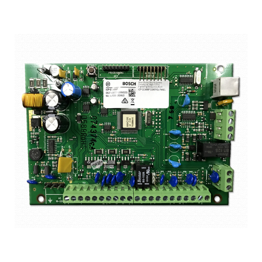
Page 82: Figure 12: Icp-Cc404 Component Overlay
IN – telecom line (street) 9 – Default switch 3 – Receiver interface connection 10 – Programming key 4 – Zone termination strip 11 – Auxiliary Module: direct link cable 5 – Output termination strip Bosch Security Systems, Inc. | 12/08 | F01U089401-02... -
Page 83: Figure 13: Telecom Connection Diagram For Australia
ICP-CC404 | Installation Guide | 20.0 Terminals and Descriptions Figure 13: Telecom Connection Diagram for Australia 1 – Control panel 8 – Telecom line 2 – Red wire 9 – Black wire 3 – Yellow wire 10 – 611 socket 1 (green): internal phone line 4 –... -
Page 84: Specifications
The Austel permit issued for this product is subject to this condition: The ICP-CC404 Control Panel can only be powered by a TF008 Plug Pack (Approval Number Q92128). 21.3 New Zealand Telepermit Notes •... -
Page 85: Programming Sheets
ICP-CC404 | Installation Guide | 22.0 Programming Sheets 22.0 Programming Sheets Location Default/ Options/Notes Function Programming Entry 0 0 0 0 0 0 0 0 0 0 0 0 0 0 0 0 000 to 015 0 = 10 and telephone termination = 0... - Page 86 Alarm Link Options 4 Exit from upload/download connection on alarm Refer to page 40 8 External modem module (CC811) required 181 to 184 1 2 3 4 Installer Code Refer to page 51 Bosch Security Systems, Inc. | 12/08 | F01U089401-02...
- Page 87 ICP-CC404 | Installation Guide | 22.0 Programming Sheets Location Default/ Options/Notes Function Programming Entry The fifth location in each user code is the authority level: 185 to 264 Arm/disarm User Codes Arm only Refer to page 51 Arm/disarm and open/close reports...
- Page 88 5 Latching arm in STAY Mode 12 Momentary arm and disarm in STAY Mode 6 Latching disarm from STAY Mode 13 Momentary arm in STAY Mode 14 Momentary disarm from STAY Mode Bosch Security Systems, Inc. | 12/08 | F01U089401-02...
- Page 89 ICP-CC404 | Installation Guide | 22.0 Programming Sheets Location Default/ Options/Notes Function Programming Entry 1 to 15 Number of times siren operates until lockout Swinger Shutdown Count for Siren Refer to page 59 1 to 15 Number of times dialer operates until lockout...
- Page 90 14 Normally low, latching open 7 Normally open, latching low The fourth location of the output definition is the time base. The options are: 1 200 ms 1 min 2 1 sec 1 hr Bosch Security Systems, Inc. | 12/08 | F01U089401-02...
- Page 91 ICP-CC404 | Installation Guide | 22.0 Programming Sheets Location Default/ Options/Notes Function Programming Entry The fifth and sixth locations of the output definition provide the time base multiplier. Enter a value between 368 to 397 01 and 99. Outputs (continued) One Shot Mode When you program the output polarity as one shot, the time base is multiplied by the time base multiplier.
- Page 92 Location 907: Month of the year (tens digit) Refer to page 72 Location 908: Month of the year (units digit) Location 909: Current year (tens digit) Location 910: Current year (units digit) Bosch Security Systems, Inc. | 12/08 | F01U089401-02...
-
Page 93: Country Codes
Comoros Mauritania Lithuania Oman Congo Mauritius Luxembourg Pakistan Costa Rica Micronesia Macedonia Qatar Cuba Monaco Malaysia Syria Djibouti Mongolia Malta Ukraine Dominica Rep. Mozambique Mexico East Timor Namibia Netherlands Algeria Ecuador Nauru Bosch Security Systems, Inc. | 12/08 | F01U089401-02... - Page 94 Country Code Country Code Country Code Country Code New Zealand Bahrain El Salvador Nepal Nigeria French Equatorial Gui Nicaragua Polynesia Norway Iceland Eritrea Niger Peru Israel Ethiopia Palau Philippines Lebanon Fiji Panama Bosch Security Systems, Inc. | 12/08 | F01U089401-02...
- Page 95 MAINS Indicator............17, 18 Exit..................38 Off Indicator..............18 FAULT Indicator............16, 18 On Indicator..............18 Features STAY ................16 Solution 404...............7 STAY Indicator .............. 17 Fire Alarm ................21 System Disarmed............17 Forced Arming............18, 19, 20 Bosch Security Systems, Inc. | 12/08 | F01U089401-02...
- Page 96 Option Bits........10, 40, 49, 52, 56, 57 Codepad Duress Alarm ..........66 Via Programming Key ...........10 Codepad Fire Alarm ............65 Via Remote Codepad............9 Codepad Medical Alarm ..........65 Programming Key ............10, 76 Bosch Security Systems, Inc. | 12/08 | F01U089401-02...
- Page 97 Trouble Reports ..............59 User Codes................50 Adding Or Changing ............. 32 Deleting..............32, 33 Walk Test Mode..............36 Warranty Statement............83 Zone EOL Resistor Value ............52 Isolating Allowed............57 Options 1 ................. 53 Bosch Security Systems, Inc. | 12/08 | F01U089401-02...
- Page 98 Bosch Security Systems, Inc. 130 Perinton Parkway Fairport, NY 14450-9199 USA www.boschsecurity.com © 2008 Bosch Security Systems, Inc. F01U089401-02...