Table of Contents
Advertisement
TELEDYNE
ANALYTICAL INSTRUMENTS
OPERATING INSTRUCTIONS
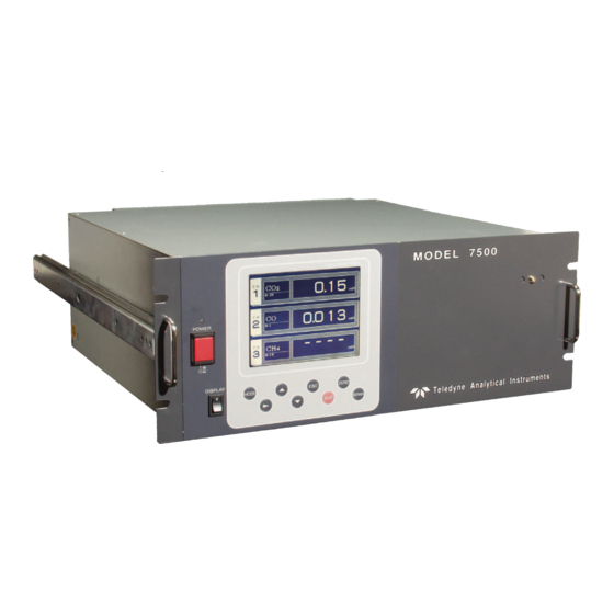
Series Model 7500
Infrared Gas Analyzer
HIGHLY TOXIC AND OR FLAMMABLE LIQUIDS OR GASES MAY BE PRESENT IN THIS
MONITORING SYSTEM.
PERSONAL PROTECTIVE EQUIPMENT MAY BE REQUIRED WHEN SERVICING THIS SYSTEM.
HAZARDOUS VOLTAGES EXIST ON CERTAIN COMPONENTS INTERNALLY WHICH MAY PERSIST
FOR A TIME EVEN AFTER THE POWER IS TURNED OFF AND DISCONNECTED.
ONLY AUTHORIZED PERSONNEL SHOULD CONDUCT MAINTENANCE AND/OR SERVICING.
BEFORE CONDUCTING ANY MAINTENANCE OR SERVICING CONSULT WITH AUTHORIZED
SUPERVISOR/MANAGER.
P/N
M7500
07/07/11
DANGER
Advertisement
Table of Contents

Related Manuals for Teledyne 7500 Series


Summary of Contents for Teledyne 7500 Series
-
Page 1: Teledyne Analytical Instruments
TELEDYNE ANALYTICAL INSTRUMENTS OPERATING INSTRUCTIONS Series Model 7500 Infrared Gas Analyzer DANGER HIGHLY TOXIC AND OR FLAMMABLE LIQUIDS OR GASES MAY BE PRESENT IN THIS MONITORING SYSTEM. PERSONAL PROTECTIVE EQUIPMENT MAY BE REQUIRED WHEN SERVICING THIS SYSTEM. HAZARDOUS VOLTAGES EXIST ON CERTAIN COMPONENTS INTERNALLY WHICH MAY PERSIST FOR A TIME EVEN AFTER THE POWER IS TURNED OFF AND DISCONNECTED. -
Page 2: Preface
• Modification of this analyzer is strictly prohibited unless a written approval is obtained from the manufacturer. Teledyne will not bear any responsibility for a trouble caused by such a modification. • This instruction manual shall be stored by the person who actually uses the analyzer. -
Page 3: Caution On Safety
Teledyne Analytical Instruments SAFETY PRECAUTIONS Please read this section carefully to ensure using the analyzer in the correct way. The cautionary descriptions listed here contain important information about safety, so they should always be observed. Those safety precautions are ranked in 3 levels, “DANGER”, “CAUTION” and “PROHIBITED”. - Page 4 Teledyne Analytical Instruments Caution on piping DANGER In piping, the following precautions should be observed. Wrong piping may cause gas leakage. If the leaking gas contains a toxic component, there is a risk of serious accident being induced. Also, if combustible gas is contained, there is a danger of explosion, fire or the like occurring.
- Page 5 Teledyne Analytical Instruments Caution on use PROHIBITED • Do not allow metal, finger or others to touch the input/output terminals in the instrument. Otherwise, shock hazard or injury may occur. • Do not smoke nor use a flame near the gas analyzer.
-
Page 6: Table Of Contents
Teledyne Analytical Instruments CONTENTS PREFACE ..........................2 CAUTION ON SAFETY ......................3 1. OVERVIEW.........................8 2. NAME AND DESCRIPTION OF EACH PART ..............9 2.1 Description of each unit ..................9 3. INSTALLATION ........................10 3.1 Installation conditions ..................10 3.2 Installation of analyzer ..................11 3.3 Piping .........................11 3.4 Sampling ......................12... - Page 7 Teledyne Analytical Instruments 6.8 Maintenance mode …………………………………………………………………… 57 6.9 Calibration …………………………………………………………………………….. 59 6.9.1 Zero calibration …………………………………………………………… 59 6.9.2 Span calibration ………………………………………………………….. 60 7. MAINTENANCE ....................61 7.1 Daily check .................... 61 7.2 Daily check and maintenance procedures ..........61 7.3 Cleaning of measuring cell ..............62 7.3.1 Disassembly and assembly of measuring cell .......
-
Page 8: Overview
Teledyne Analytical Instruments 1. OVERVIEW The Model 7500 infrared gas analyzer measures the concentrations of CO2, CO, CH4, SO2 and O2 contained in sample gas. CO2, CO, CH4 and SO2 are measured by non-dispersion infrared method, while O2 is measured by paramagnetic method. A maximum of 4 components including O2 (a maximum of 3 components for other than O2 measurement) are simultaneously measurable. -
Page 9: Name And Description Of Each Part
Teledyne Analytical Instruments 2. NAME AND DESCRIPTION OF EACH PART 2.1 Description of each unit Name Description 1. Handle Draws the analyzer unit from the case. 2. Power switch Turns ON/OFF this analyzer. 3. Switch for back light Turn ON/OFF the back light of display. -
Page 10: Installation
Teledyne Analytical Instruments 3. INSTALLATION DANGER This unit is not explosion-proof type. Do not use it in a place with explosive gases to avoid explosion, fire or other serious accidents. CAUTION • For installation, observe the rule on it given in the instruction manual and select a place where the weight of gas analyzer can be endured. -
Page 11: Installation Of Analyzer
Teledyne Analytical Instruments 3.2 Installation of analyzer There are two methods of installing the analyzer. For detailed dimensions, see Chapter 9.3. Note: The mounting method should be selected to meet the installation requirements since the top cover must be detached from the gas analyzer for maintenance and check. -
Page 12: Sampling
Teledyne Analytical Instruments Observe the following when connecting the gas pipes. • The pipes should be connected to the gas inlet and outlet at the rear panel of the analyzer, respectively. • Connect the sampling system to the instrument by using corrosion-resistant tube such as Teflon, stainless steel, or polyethylene. - Page 13 Teledyne Analytical Instruments (2) Sampling gas flow rate A flow rate of sampling gas must be 1 L/min ±0.5 L/min. A flow meter should be provided as shown in Fig. 3-2 to measure flow rate values. (3) Preparation for standard gas Prepare the standard gas for zero/span calibration.
- Page 14 The system configuration may vary depending upon the nature of measured gas, coexistent gases or application. A typical configuration diagram is shown in Fig. 3-2. Since a system configuration depends upon measured gas, consult with Teledyne. Fig. 3-2 A typical example of sampling system...
-
Page 15: Wiring Method
Teledyne Analytical Instruments 3.5 Wiring method Caution on wiring CAUTION • Wiring work must be performed with the main power set to OFF to prevent electric shocks. • Enforce construction of class-D grounding wire by all means. If the specified grounding construction is neglected, a shock hazard or fault may be caused. - Page 16 (3) O2 sensor input: terminal block 2 (1 – 2) Input signal: External zirconia O2 analyzer: Zirconia O2 sensor signal (Teledyne output) External O2 analyzer: 0 to 1 VDC (DC input resistor of 1MΩ or more) • It is used when the external zirconia O2 analyzer or external O2 analyzer is specified as order.
- Page 17 Teledyne Analytical Instruments (4) Contact input (DI): terminal block 2 (13 to 20), terminal block 3 (5 to 10) • It is for a contact input at no voltage. An input is provided when switching to short circuit (on) or open (off).
- Page 18 Teledyne Analytical Instruments (7) List of terminal blocks 1 to 5 *1) Unused terminals are used for internal connection and should not be used as repeating terminals either. *2) O2 sensor input is used when an external O2 analyzer is selected.
- Page 19 Teledyne Analytical Instruments 8) Description on terminal block Terminal block 1 <TN1> Terminal block for analog output (non-isolated output) Output : 4 to 20 mA or 0 to 100V DC Between 1 – 2: CH5 output Between 3 – 4: CH4 output Between 5 –...
- Page 20 Teledyne Analytical Instruments Terminal block 3 <TN3> Between 1 – 4: For internal connection. Must not be wired. (Must not be used as junction terminal.) Between 5 – 6: Remote hold input. No hold when open. Output hold when short-circuited.
- Page 21 Teledyne Analytical Instruments Terminal block 4 <TN4> Between 1 – 2: CH4 span calibration contact output Between 3 – 4: CH3 span calibration contact output Between 5 – 6: CH2 span calibration contact output Between 7 – 8: CH1 span calibration contact Between 9 –...
- Page 22 Teledyne Analytical Instruments Terminal block 5 <TN5> 1 and 11 – 14: For internal connection. Must not be wired. (Must not be used as junction terminal.) Between 2 - 3 and 3 - 4: CH3 alarm output. Conductive at 2 – 3 and open at 3 – 4 when set value is exceeded.
- Page 23 Teledyne Analytical Instruments (9) Timing of calibration contact output 1. Manual calibration (See “6.9 Calibration”) 2. In case of automatic calibration (example shown in 6.4.1, Automatic calibration settings) Model 7500 Instruction Manual...
-
Page 24: Operation
Teledyne Analytical Instruments 4. OPERATION 4.1 Preparation for operation (1) Check of gas sampling tube, exhaust tube and wiring Check that the pipes are correctly connected to the gas sampling port and drain port. Check that the analyzer is correctly wired as specified. -
Page 25: Description Of Display And Operation Panel
Teledyne Analytical Instruments 5. DISPLAY AND OPERATION PANEL This section describes the display and operation panel of the gas analyzer. It also explains the name and description of function on the operation panel. See Fig. 5-1. 5.1 Name and description of operation panel •... -
Page 26: Overview Of Display And Operation Panel
Teledyne Analytical Instruments 5.2 Overview of display and operation panel Figure 5.2 Model 7500 Instruction Manual... -
Page 27: Overview Of Display Screen
Teledyne Analytical Instruments 5.3 Overview of display screen (1) Measurement mode screen On turning on the power switch, the Measurement Mode screen will appear. The measurement screen depends on the number of components. The following screen configuration shown as an example is for CO2, CO, O2 (Output at channel 6). - Page 28 Teledyne Analytical Instruments • O2 correction concentration average value: CH (component) where “AV / CV” is displayed as “AV / CV CO” in the component display and O2 average value, a value obtained by averaging O2 conversion concentration value or O2 concentration value in a fixed time is output every 30 seconds.
- Page 29 Teledyne Analytical Instruments (3) Contents of measured channel (CH) The contents in each measured CH corresponding to the type are given below: Type code Contents 6th digit 7th digit digit A, B, C A, B, C Y, B A, B, C...
-
Page 30: General Operation
Teledyne Analytical Instruments 5.4 General operation • Measurement mode The measurement mode can be displayed for up to 5 channels in a single screen. When viewing a channel beyond the 5 channels, press the ( or ) key and the screen can be scrolled one by one channel at a time. -
Page 31: Setting And Calibration
Teledyne Analytical Instruments 6. SETTING AND CALIBRATION 6.1 Changeover of range This mode is used to select the ranges of measured components. 1. During measurement, press the MODE key to display the User mode. 2. Point the cursor to “Changeover of Range”. Press the ENT key. -
Page 32: Calibration Setting
Teledyne Analytical Instruments 6.2 Calibration setting This mode is used to set calibration concentration and actions. The calibration setting involves calibration concentration, zero calibration, calibration range and auto-calibration component. 6.2.1 Setting of calibration concentration It allows you to set concentrations of the standard gas (zero and span) of each channel used for calibration. - Page 33 Teledyne Analytical Instruments 5. In the “Calibration Concentration Selection” screen that appears, select any concentration item you want to set by pressing the UP, DOWN, and RIGHT key. Note: Analyzers other than the zirconia O2 instrument cannot perform zero setting.
-
Page 34: Setting Of Manual Zero Calibration
Teledyne Analytical Instruments 6.2.2 Setting of manual zero calibration If zero calibration is to be made manually, select whether to calibrate all components at once or each of them separately upon selection. 1. During measurement, press the MODE key to display the User mode. - Page 35 Teledyne Analytical Instruments 5. In the “Manual Calibration Selection” screen that appears, select “At once” or “Each” by pressing the UP or DOWN key. When selecting “Both”, the CH (components) to be set can be zero-calibrated at the same time. When selecting “Each”, either of the CH (components) to be selected is zero-calibrated. After setting, press the ENT key, and the calibration you specified is carried out.
-
Page 36: Setting Of Calibration Range
Teledyne Analytical Instruments 6.2.3 Setting of calibration range This mode is used to set if the range of each CH (component) at the calibration manual calibration or auto calibration) should be calibrated with a single range or 2 ranges. 1. During measurement, press the MODE key to display the User mode. - Page 37 Teledyne Analytical Instruments 5. In the “Calibration Selection” screen that appears, select “Both” or “Current” by pressing the UP or DOWN key. • When selecting “both”, Range 1 and Range 2 of the set CH are calibrated together. • When selecting “Current”, the range alone displayed at the set CH is calibrated.
-
Page 38: Setting Of Auto-Calibration Component
Teledyne Analytical Instruments 6.2.4 Setting of auto-calibration component It sets the CH (component) to be calibrated in the auto- calibration. 1. During measurement, press the MODE key to display the User mode. 2. Point the cursor to “Setting about Calibration” by pressing the UP or DOWN key. - Page 39 Teledyne Analytical Instruments 5. In the “Auto Calibration Selection” screen that appears, select “enable” or “disable” by pressing the UP or DOWN key. After setting, press the ENT key. To close Auto Calibration Component setting To close “Setting of Auto Calibration Component” or to cancel this mode midway, press the ESC key.
-
Page 40: Alarm Setting
Teledyne Analytical Instruments 6.3 Alarm setting 6.3.1 Setting of alarm values This mode is used to set the upper and lower limit value to provide an alarm output during measurement. Before changing the alarm setting, set the ON/OFF to OFF. - Page 41 Teledyne Analytical Instruments After setting, the alarm setting is now completed by pressing the ENT key. To close the “Alarm Setting” To close the “ Alarm Setting” or to cancel this mode midway, press the ESC key. A previous screen will return.
-
Page 42: Hysteresis Setting
Teledyne Analytical Instruments 6.3.2 Hysteresis setting To prevent chattering of an alarm output near the alarm setting values, set hysteresis. 1. In the “Alarm Setting CH Selection” screen that appears, point the cursor to “Hysteresis” by pressing the UP or DOWN key. Press the ENT key. -
Page 43: Setting Of Auto Calibration
Teledyne Analytical Instruments 6.4 Setting of auto calibration 6.4.1 Auto calibration Auto calibration is automatically carried out when zero calibration and span calibration are set. Before changing the setting of auto calibration, set the ON/OFF to OFF. 1. During measurement, press the MODE key to display the User mode. - Page 44 Teledyne Analytical Instruments Auto calibration status contact output is closed during auto calibration, and is open in other cases. Setting range Cycle: 1 to 99 hours or 1 to 40 days (initial value 7 days) Flow time: 60 to 599 sec (initial value 300sec) CAUTION When an auto calibration starts, the measurement screen automatically appears.
-
Page 45: Forced Stop Of Auto Calibration
Teledyne Analytical Instruments 6.4.2 Forced stop of auto calibration This mode is used to cancel the auto calibration forcedly. 1. In the Menu mode that is displayed, point the cursor to “Setting of Auto Calibration” by pressing the UP or DOWN key. - Page 46 Teledyne Analytical Instruments “Auto Calibration” screen Example In case where setting the auto calibration components (see Item 6.2.4) to “CH1: enable” and “CH2: enable”. • Zero calibration A message, “Zero calibration” blinks at CH1 and CH2. • CH1 span calibration A message, “Span calibration”...
-
Page 47: Setting Of Auto Zero Calibration
Teledyne Analytical Instruments 6.5 Setting of auto zero calibration 6.5.1 Auto zero calibration Auto zero calibration is automatically carried out when zero calibration are set. Components for which a calibration is to be made are determined by setting of auto calibration component in 6.2.4. - Page 48 Teledyne Analytical Instruments Auto calibration status contact output is closed during auto zero calibration, and is open in other cases. Setting range Cycle: 1 to 99 hours or 1 to 40 days (initial value 7 days) Flow time: 60 to 599 sec (initial value 300 sec) Caution •...
-
Page 49: Forced Stop Of Auto Zero Calibration
Teledyne Analytical Instruments 6.5.2 Forced stop of auto zero calibration This mode is used to cancel the auto zero calibration forcedly. 1. In the Menu mode that is displayed, point the cursor to “Setting of Auto Zero Calibration” by pressing the UP or DOWN key. - Page 50 Teledyne Analytical Instruments “Auto Zero Calibration” screen Example In case where setting the auto calibration components (see Item 6.2.4) to “CH1: enable” and “CH2: enable”. • Zero calibration A message, “Zero calibration” blinks at CH1 and CH2. CAUTION During auto zero calibration, any key operation is not permitted other than operations such as key lock ON/ OFF and “Stop Auto Zero Calibration”.
-
Page 51: Peak Alarm Setting
Teledyne Analytical Instruments 6.6 Peak alarm setting When the number of peaks of which CO concentration exceeds the upper limit value exceeds the setting time, a peak alarm is outputted. This section describes how to perform various settings of peak alarm. - Page 52 Teledyne Analytical Instruments Setting range • Alarm Value: 0 to 1000 ppm 5 ppm step (initial value: 500 ppm) • Alarm Count: 1 to 99 times (initial value: 5 times) • Hysteresis: 0 to 20% of full scale (initial value: 0% of full scale) * The hysteresis setting is made in terms of full scale.
-
Page 53: Parameter Setting
Teledyne Analytical Instruments 6.7 Parameter setting It allows you to carry out the parameter setting such as time, key lock, etc., as required. Items to be set are as follows: Description of setting items • Current Time: Sets the current day of the week, hour and time. - Page 54 Teledyne Analytical Instruments 4. In the Parameter Setting screen that appears, enter the numeric values and set the items. Entering the numeric values or setting the items should be carried out by using the or key. To move the cursor to the right, press the key.
- Page 55 Teledyne Analytical Instruments (2) Auto calibration (3) External hold (4) Screen display during holding The “Holding” message blinks on the measuring screen. Since the screen displays the process of calibration is displayed during the manual calibration, “Holding” is not displayed even if the screen is held, but the screen is displayed with the hold extending time.
- Page 56 Teledyne Analytical Instruments Average period It allows you to set an average period of the average value of O2 correction. It enables you to set an average time of 1 to 59 minutes (1- minute step) or 1 to 4 hours (1-hour step).
-
Page 57: Maintenance Mode
Teledyne Analytical Instruments 6.8 Maintenance mode This mode is used for check of sensor input values, display of error log files or setting of passwords. First, enter a password and then use it from the next operation. This mode is displayed by selecting the Maintenance Mode from “6.7 Parameter Setting”... - Page 58 Teledyne Analytical Instruments • O2 correction reference value setting screen • Password Setting screen Description of Password Setting screen It enables you to set a password to be used when switching the parameter setting mode to the maintenance mode. Note: The password set herein must be managed for safety. Failure to enter the correct password will not open the Maintenance mode.
-
Page 59: Calibration
Teledyne Analytical Instruments 6.9 Calibration 6.9.1 Zero calibration It is used for zero point adjustment. For zero calibration gas, see 3.3 (3), Preparation for standard gas in Sampling. Use a gas according to application. 1. Press the ZERO key on the Measurement screen to display the Manual Zero Calibration screen. -
Page 60: Span Calibration
Teledyne Analytical Instruments 6.9.2 Span calibration It is used to perform a span point adjustment. Supply calibration gas with concentration set to the span value to perform the span calibration. For the span calibration gas for the SO2, CO2, CO, H4 measurement, use the standard gas with a concentration of 90% or more of the range value. -
Page 61: Maintenance
Teledyne Analytical Instruments 7. MAINTENANCE 7.1 Daily check (1) Zero calibration and span calibration 1. It is used for zero point adjustment. For calibration, refer to 6.9.1, Zero calibration. 2. After zero calibration, perform span calibration. For calibration, refer to 6.9.2, Span calibration. -
Page 62: Cleaning Of Measuring Cell
Teledyne Analytical Instruments 7.3 Cleaning of measuring cell Entry of dust or water drops in the measuring cell contaminates the interior of the cell, thus resulting in a drift. Clean the inside if dirty. Then, check the sampling device, especially the filter, to prevent the cell from being contaminated by dust or mist. - Page 63 Teledyne Analytical Instruments Number Name Screw (for fixing light source unit) Screw (for fixing detector) Screw (for fixing base plate) Base plate Light source unit Screw (for fixing support) Screw (for fixing cell retainer) Chopper motor connector Filter Support Cell retainer...
- Page 64 Teledyne Analytical Instruments (2) How to remove block cell (See Fig. 7-2) 1. For Step 1 to 4, see Item 7.3.1, (1) How to remove pipe cell. 5. Remove the connector to the detector output cord from the printed board. For the 2-component analyzer, remove the output cord connector of the 2-component analyzer detector (No.
- Page 65 Teledyne Analytical Instruments Number Name Screw (for fixing light source unit) Filter Screw (for fixing detector) Base plate Light source unit Screw (for fixing block cell) Block cell Infrared transmission window (window holder) O-Ring Screw (for fixing base plate) Chopper motors connector...
- Page 66 Teledyne Analytical Instruments 3) How to remove measuring unit (See Fig. 7-3) 1. For Step 1 to 4, see Item 7.3.1(1), How to remove pipe cell. 2. Remove the detector output cord connector from the printed board. 3. Remove wiring to the 2-pin terminals of the infrared ray light source assembly and chopper motor pin connector (No.
-
Page 67: How To Clean Cell
Teledyne Analytical Instruments 7.3.2 How to clean cell 1. To clean the cell inside or infrared ray transmission window, first clear large dirt of it with a soft brush and then wipe with soft cloth lightly. Donʼt use hard cloth. -
Page 68: Troubleshooting
Teledyne Analytical Instruments 8. TROUBLESHOOTING 8.1 Error message If errors occur, the following contents are displayed. Error display Error contents Probable causes Error No. 1 Sector motor rotation detector signal is faulty. • Infrared ray light source is faulty. • Sector motor rotation is faulty or stopped. - Page 69 Teledyne Analytical Instruments In case of Error No. 5 and No. 7 (2) Error log file If error occurs, the history is saved in an error log file. The error log file exists in the maintenance mode. * Up to 14 errors can be saved in the error history; the oldest error will be deleted one by one every time a new occurs.
-
Page 70: Specifications
For signal input from externally installed O2 sensor. 1 L / min (when required) Signal requirement; (1) Signal from Teledyneʼs Zirconia O2 sensor (TYPE: ZFK7) (2) 0 to 1V DC from an O2 sensor Input section is not isolated. This feature is effective when an O2 sensor is not built in. - Page 71 Teledyne Analytical Instruments (2) Standard functions Auto zero calibration: Auto zero calibration is carried out periodically at the preset cycle. This cycle is independent on “Auto Output signal holding: calibration” cycle. Output signals are held during manual and auto When zero calibration gas and solenoid valve for...
- Page 72 Teledyne Analytical Instruments CS: measured concentration of sample gas Interference from other gases: Os : Measured O2 concentration On: Standard O2 concentration (value changeable by Interference setting) component ana- analyzer ana- ana- ana- *The upper limit value of the fractional part in this...
-
Page 73: Code Symbols
Teledyne Analytical Instruments 9.2 Code symbols Model 7500 Instruction Manual... - Page 74 Teledyne Analytical Instruments Model 7500 Instruction Manual...
- Page 75 Teledyne Analytical Instruments <Code specification for ordering> (1) Code symbols should be specified. (2) Range combination should be the one allowed in separate tables. (note 1) “Y” should be specified when only O2 measurement is necessary. (note 2) External O2 sensor signal should be 0-1VDC linear of full scale, when “ B ” is specified at the 6th digit.
- Page 76 Teledyne Analytical Instruments Measurable component and range - availability check table - Model 7500 Instruction Manual...
- Page 77 Teledyne Analytical Instruments Table 5: Triple component analyzer (CO2, CO, CH4) Covered in combination of Table 2, Table 3 and Table 4. Model 7500 Instruction Manual...
-
Page 78: Outline Diagram
Teledyne Analytical Instruments 9.3 Outline diagram (1) Main unit Model 7500 Instruction Manual... - Page 79 Teledyne Analytical Instruments (2) Accessory slide rail (unit: mm) * The slide rails are attached to this equipment when designated. Model : 305A-20/Accuride International Inc. 19-inch rack mounting method: The mass of the instrument should be supported at the bottom of the unit (or the side of the unit when mounted with the slide rails).
-
Page 80: Appendix
Teledyne Analytical Instruments Appendix Drawing List Bulkhead option, for rack mount option see D79104 Outline diagram Section 9.3 Model 7500 Instruction Manual...