Table of Contents
Advertisement
Available languages
Available languages
Sno-Throo
Owner/Operator
Manual
Models
932036-524
932037-724
932504-524
932505-724
U.S. Patents Pending
_
_
_ENGLISH
FRANQAIS
ESPAKIOL
Transfer
model &
serial number
label from
product
registration
here.
Coller I'autocollant du
module et du numero de
serie dans cet encadr&
Transferir aquila etiqueta
del modelo y nOmero de
serie del registro del
producto.
03249300C 3/04
Supersedes 03249300,A,B
Printed in USA
Advertisement
Table of Contents
Troubleshooting

Related Manuals for Ariens Sno-Thro 932036-524


Summary of Contents for Ariens Sno-Thro 932036-524
- Page 1 Sno-Throo Owner/Operator Manual Models 932036-524 932037-724 932504-524 932505-724 U.S. Patents Pending _ENGLISH FRANQAIS ESPAKIOL Transfer Coller I'autocollant du model & module et du numero de serial number serie dans cet encadr& label from Transferir aquila etiqueta product del modelo y nOmero de registration here.
- Page 2 ARIENS COMPANY, certify that: - Nous, soussignes ARIENS COMPANY, certifions que :- Der Unterzeichnete, ARIENS COMPANY, bescheinigt, dass: - La sottoscritta societ&, ARIENS COMPANY, certifica che: - Nosotros, los abajo firmantes, ARIENS COMPANY, certificamos que: - Undertegnede, ARIENS COMPANY, bekrefter at: -...
- Page 3 Philip J ,Smucker: 5/21/2003 Manager ofProduct Conformance (Keeper Date - Data - ofTechnical File) - Responsable dela Datum - Signature - Firma- conformite des produits (en possession Fecha - Dato - Unterschrift- Signatu r- dudocument technique) - Leiter der P&iv&ys - Data Namnteckning - Produkt(Jbereinstimmung...
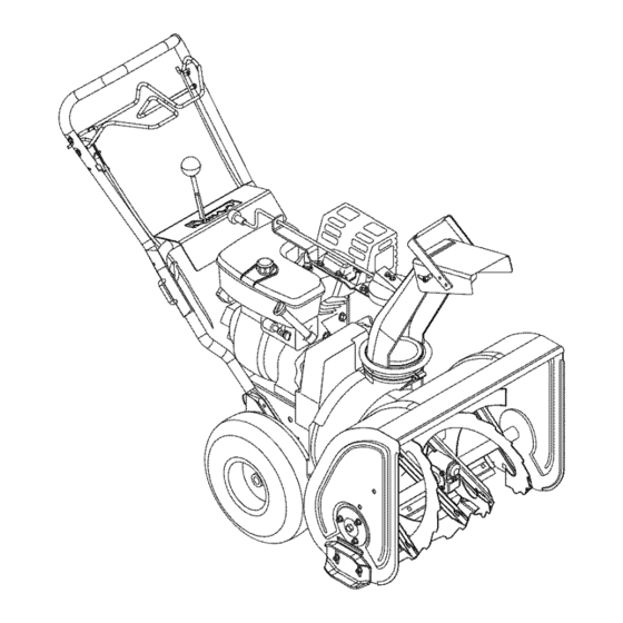
- Page 4 ENGLISH ESPANOL FRAN(_AIS 1.Traction Drive C lutch Bail 1.Levier d'embrayage 1.Palanca del e mbrague I'entrafnement dela delatransmisiSn dela 2.Speed Selector traction tracciSn 3.Chute Crank 2.Selecteur devitesses 2.Selector develocidad 4.Muffler Guard (932504, 3.Manivela delatolva 505) 3.Manivelle delagoulotte 4.Garant dusilencieux 4. Protector del s ilenciador 5.Discharge Chute...
- Page 5 0S2420 0S0503 Figure 1...
- Page 6 PRODUCT REGISTRATION The contents will provide you with safety instructions for the safe use of your unit during The Ariens dealer must register the product at normal operation and maintenance. the time of purchase. Registering the product will help the company process warranty claims...
- Page 7 If you do not 6. Fill out a Product Registration Card and understand or have difficulty following the return the card to the Ariens Company or instructions, contact your nearest Ariens go to www.ariens.com. Dealer for assistance.
- Page 8 REQUIRED OPERATOR TRAINING SAFETY DECALS AND LOCATIONS Original purchaser of this unit was instructed by the seller on safe and proper operation. If ALWAYS replace missing or damaged Safety unit is to be used by someone other than Decals. Refer to figure below for Safety Decal original purchaser;...
- Page 9 2. DANGER! NEVER allow children to operate or play on or near unit. Be alert and shut off unit if children enter area. ROTATING PARTS! Stop engine DO NOT allow adults to operate unit without and remove key before clearing. proper training.
- Page 10 Never direct discharge towards persons Abnormal Vibrations are a warning of trouble. property that may beinjured ordamaged Striking a foreign object can damage unit. thrown objects. Use e xtreme caution ongravel Immediately stop unit and engine. Remove surfaces. Stay a lert forhidden hazards or key and wait for all moving parts to stop.
- Page 11 This product isequipped with aninternal ALWAYS keep p rotective structures, guards, combustion type engine. DO NOT u se unit on and panels ingood r epair, inplace a nd ornear any unimproved, forest-covered securely fastened. NEVER modify orremove brush covered land unless exhaust system i s safety devices.
- Page 12 Install Discharge Chute and Chute WARNING: AVOID INJURY. Read Crank (Figure 5, 6, and 7) and understand the entire Safety section before proceeding. NOTE: See Figure 5 for the items to install on the unit. 1. Grease chute seat (if not already greased).
- Page 13 932037,505 932036, 504 1. Discharge Chute 2. Retainer Clip 3. Mounting 4. Chute Ring 5. Chute Bracket Figure 7 OS4500 Check Tire Pressure Check tire pressure and adjust to the pressure listed on tire sidewall. Check Auger Gearoase Check oil level in auger gearcase (see Service and Adjustments).
- Page 14 Ignition Switch WARNING: AVOID INJURY. Read and understand the entire Safety section before proceeding. 1. "Stop"- pulled out 2. "Run"- pushed in NOTE: DO NOT twist key WARNING: To avoid injury to hands after it is inserted. and feet, always disengage clutches, shut off engine, and wait for all Key Switch has two positions: movement to stop before unclogging...
- Page 15 Choke Control Knob IMPORTANT: DO NOT force frozen chute controls. Start engine and run for 3-5 minutes 1. Choke Closed position: to thaw. If still frozen, take to warm place until chokes off air to engine for controls are free. easier start.
- Page 16 FILLING FUEL TANK 4. Adjust Runners Check and adjust Runners (see Service and Adjustments). Allow 1/8 in. (3 mm) between WARNING: AVOID INJURY. Read and understand the entire Safety scraper blade and hard, smooth surface(s). section before proceeding. Allow 1-1/4 in. (30 mm) between scraper blade and uneven or gravel surfaces.
- Page 17 7.Grasp starter handle and pull r ope o ut 2. Run Impeller a few minutes after use to slowly until itpulls h arder. Let r ope r ewind prevent freeze-up of Impeller. slowly. 3. Release Attachment Clutch Bail and wait 8.Pull rope w ith arapid c ontinuous full a rm for all moving parts to come to a complete...
- Page 18 _oid CHECK FASTENERS Ariens Dealers will provide any service or adjustments which may be required to keep Make sure all hardware is tightened properly. your unit operating at peak efficiency. Should engine service be required, contact an Ariens CHECK CLUTCHES...
- Page 19 2.Add lubricant ifrequired. Allow oil t odrain tolevel ofplug a nd replace plug. IMPORTANT: Use only A riens special gear lubricant L-2 (Part Number 00008000). 0S1830 1.Auger Gearcase 2.Filler Plug Figure 9 GENERAL LUBRICATION IMPORTANT: Wipe each fitting clean before and after lubrication.
- Page 20 3. Reposition scraper blade flush with runners and tighten lock nuts. SHEAR BOLTS OS0115 IMPORTANT: Use only Ariens shear bolts for replacement. Use of any other type of shear 1. Pinion bolt may result in severe damage to unit. 2. Chute Gear...
- Page 21 2.Drive shear bolt t hrough hole ( ifshear bolt 8. Adjust pivot pin as needed so unit travels was broken this will d rive r emaining part forward when speed selector lever is in from shaft). first forward position and backward when 3.Secure shear bolt with nut.
- Page 22 ATTACHMENT DRIVE BELT REPLACEMENT Remove Attachment Drive Belt (Figures 16 and 17) 1. Shut off engine, remove key, disconnect spark plug wire and allow unit to cool completely. 2. Remove two screws securing belt cover to unit and remove belt cover. 3.
- Page 23 1. Attachment Belt Idler 2. Belt Finger 3. Attachment Drive Belt 4. Traction Drive Belt 5. Camshaft Pulley 6. Engine Sheave 7. Traction Belt Idler 8. Attachment Pulley 9. Attachment Idler OS0464 Figure 17 TRACTION DRIVE BELT NOTE: To gain clearance, engage traction clutch and if necessary pull back attachment REPLACEMENT...
- Page 24 ATTACHMENT CLUTCH/BRAKE b.With the clutch bail disengaged, loosen the control cable mounting nuts ADJUSTMENT on the attachment clutch arm (Figure 21). WARNING: IMPROPER c. Pull up on the cable body to remove ADJUSTMENT could result in cable slack. unexpected movement of auger and d.
- Page 25 To adjust traction clutch (Figure 21): 1. Loosen jam nut on traction cable adjustment barrel. 2. Turn adjustment barrel up the cable to decrease the distance between clutch bail and handlebar. Turn the adjustment barrel down the cable to increase the distance between clutch bail and handlebar.
- Page 26 FRICTION DISC REPLACEMENT 9. Remove bearing cap/bushing and washer from right side of unit. 10. Reinstall nuts on screws through side frame to keep screws in place. 11. Carefully tap two (2) roll pins out of center and right end of shaft. 12.
- Page 46 Palanca del embrague del accesorio- Palanca derecha ADVERTENClA: EVITAR LESIONES. Antes de proceder, leer y comprender la secci6n de Seguridad completa. ADVERTENClA: Para evitar lesiones en las manos yen los pies, siempre 0L1692 desactivar los embragues, apagar el Comprimir la palanca del embrague del motor y esperar a que se detenga accesorio contra el manillar (1) para activar el todo el movimiento antes de...
- Page 47 Selector de velocidad Arranque electrico El selector de velocidad controla el El arranque electrico arrancara el motor desplazamiento de la unidad en una direcci6n correctamente estrangulado y encendido hacia adelante o en marcha atras al ser cuando se oprime el bot6n de arranque. colocado en una de las ranuras de la Consultar Arranque y apagado.
- Page 49 3.Si e lpropulsor esta congelado (no se IMPORTANTE: Se debe permitir que la puede tirar d elamanilla), mover la unidad y el motor se ajusten a la temperatura unidad aunarea c aliente ypermitir que ambiente antes de quitar la nieve. Antes de sedescongele para p revenir dafios.
- Page 50 2.Enchufar elcable d eextensi6n EXTRACCION DE LA NIEVE enchufe con toma d etierra d e3clavijas IMPORTANTE: Se debe permitir que la de120 V. unidad y el motor se ajusten a la temperatura 3.Girar latolva d edescarga hacia a delante. ambiente antes de quitar la nieve. 4.Asegurarse deque elembrague NOTA: El embrague del accesorio se debe...
- Page 51 Si e lmotor requiere mantenimiento, ponerse encontacto con un concesionario Ariens ouncentro deservicio Mantenimiento deunfabricante demotores autorizado. Comprobaci6n de los ADVERTENClA: EVITAR LESIONES. Antes de proceder, leer y afianzadores...
- Page 52 2. Afiadir lubricante si es necesario. Dejar que el aceite se drene al nivel del tap6n y reemplazar el tap6n. IMPORTANTE: Usar solamente lubricante para engranajes especial Ariens L-2 (N0mero de pieza 00008000). OS1373 0S1830 Grasa Aceite 1. Caja de engranajes del sinfin Figura 10 2.
- Page 53 GUJA8 Las guias se deben ajustar (Figura 13) segen ADVERTENClA: EVITAR LESIONES. Antes de proceder, leer y Io requieran las condiciones. comprender la secci6n de Seguridad 1. Colocar la unidad en un superficie dura, completa. firme y nivelada. 2. Ajustar las guias colocando un DEFLECTOR DE LA TOLVA espaciador del ancho deseado debajo del DE DESCARGA...
- Page 54 Io largo de la varilla de cambio hasta IMPORTANTE: Usar solamente pernos que quede alineada con el agujero protectores Ariens de repuesto. La utilizaci6n correspondiente en la palanca del de cualquier otro tipo de perno de seguridad selector de velocidad.
- Page 55 REEMPLAZO DE LA CORREA DE TRANSMISION DEL ACCESORIO Extraer la correa de la transmision accesorio (Figuras 16 y 17) 1. Parar el motor, quitar la Ilave, desconectar el cable de la bujia y dejar que la unidad se enfrie completamente. 2.
- Page 56 6.Ajustar elembrague segQn Ajuste del 8. Volver a colocar la manivela de la tolva y freno del propulsor/embrague fijarla con el pasador de resorte. acessorio abajo. 9. Volver a colocar la cubierta de la correa y 7. Volver a instalar la correa de la tolva y la sujetarla con tomillos.
- Page 57 AJUSTE DEL FRENO/EMBRAGUE b.Con la palanca de embrague desactivada, aflojar las tuercas de DEL ACCESORIO montaje del cable de control en el brazo de embrague del accesorio (Figura 21). ADVERTENCIA: UN AJUSTE INCORRECTO puede resultar en un c. Tirar hacia arriba del cuerpo del cable movimiento inesperado del sinfin y el para quitar holgura del cable.
- Page 58 IMPORTANT: Si e lembrague/freno AJUSTE DEL EMBRAGUE DE LA accesorio nopuede ajustarse deacuerdo alas TRACCION DE LA TRANSMISION especificaciones, consultar alconcesionario para las reparaciones. Ajustar el embrague de tracci6n para 8.Comprobar laholgura del d edo d ela compensar el desgaste de la disco de fricci6n correa.
- Page 59 .... OS0523 1. Cable del 6. Brazo del selector de embrague tracci6n velocidad 2. Varilla 7. Pasador de selectora de chaveta y 1. Eje hexagonal 7. Tornillos de velocidad horquilla 2. Disco de fricci6n sombrerete del 3. Cable de 8. Brazo del 3.
- Page 60 12. D eslizar elconjunto del d isco d e fricci6n y 2. Deslizar el eje y las piezas acopladas en eleje hexagonal hacia l aderecha hasta el chasis, a traves del agujero del lado que elextremo izquierdo del e je salga d el derecho primero, y a continuaci6n el lado cojinete izquierdo.
- Page 61 It_] ; [,,,_o]lLll__t][_lln_] = I_To):]mI:I_v_PL*T: "] CORRECCION PROBLEMA POSIBLE CAUSA El motor no 1. Llenar el dep6sito de combustible. 1. El dep6sito de combustible esta vacio. arranca/vi ra. 2. Valvula de corte de 2. Abrir la valvula de cierre de combustible cerrada.
- Page 62 I-JI_A.'T."]=]= I=!=l_lllJ_li(o] P_'_o_;_[o_ Contactar con su concesionario autorizado Pedir las piezas a continuaci6n a traves del concesionario: Ariens acerca de los accesorios disponibles _ara la Sno-Thro. Pieza no. Descripci6n Pieza no. Descripci6n 00036800 Grasa para temperaturas altas Stens Mix (3 cartuchos de 3 oz.)
- Page 63 I_,,,,__o,_p_o]_o_[_,,l Nt_mero de modelo 932036 932504 932037 932505 Descripci6n Motor - Tecumseh HSSK50- HSSK50- OHSK70- OHSK70- 67416U 67417U 72517F 72507F Potencia maxima del motor- 3,73 (5,0) 5, 22 (7) Kw (HP) Velocidad maxima de ralenti 3600 + 150 - min q (RPM) Cilindrada - cc (cu.
- Page 64 (90) dias a partir de la fecha de compra, y Ariens Company reparara o reemplazara cuatquier pieza o accesorio...
- Page 65 Ariens Company 655 West Ryan S treet EO. B ox 157 Brillion, WI54110-0157 920-756-2141 Fax 920-756-2407 www.ariens.com WARNING The engine exhaust from this product contains chemicals known to the State of California to cause cancer, birth defects or other reproductive...