Table of Contents
Advertisement
Sno-Thro
Owner/Operator Manual
Models
932102 - 520
932103 - 624
932310 - 624
Transfer
model &
serial number
label from
Transferir aquí la etiqueta
product
del modelo y número de
registration
serie del registro del
here.
producto.
Coller l'autocollant du
modèle et du numéro de
série dans cet encadré.
®
Supersedes 03243800,A, B, C
ENGLISH
FRANÇAIS
ESPAÑOL
03243800D 5/02
Printed in USA
Advertisement
Table of Contents
Troubleshooting

Related Manuals for Ariens SNO-THRO 932102 - 520


Summary of Contents for Ariens SNO-THRO 932102 - 520
- Page 1 Sno-Thro Owner/Operator Manual Models 932102 - 520 932103 - 624 932310 - 624 Transfer Coller l’autocollant du model & modèle et du numéro de serial number série dans cet encadré. label from Transferir aquí la etiqueta product del modelo y número de registration serie del registro del here.
- Page 2 - El abajo firmante - Undertegnede, - Undertecknaren av detta dokument, - Me, allekirjoittaneet, ARIENS COMPANY, certify that the Snow Thrower - certifie que le chasse-neige - bestätigen daß die Schneefräse, verklaren dat de sneeuwschüiver - certifica che lo spazzavere - certifica que el quita nieves - attesterer at sneslynger - bevitner at snøfreseren - försäkrar att...
- Page 3 Representative Measured Sound Power Level Niveau de puissance acoustique représentatif Repräsentativer gemessener Geräuschpegel Livello di potenza sonora rappresentativo rilevato Nivel de potencia acústica representativo medido Representativt målt lydeffektnivå Representativ uppmätt ljudnivå Edustava, mitattu äänen tehotaso 100 dB Stated Sound Power Levels are established following Annex V “Internal Control of Production” of directive 2000/14/EC and assessment procedure EN-ISO 3744:1995.
-
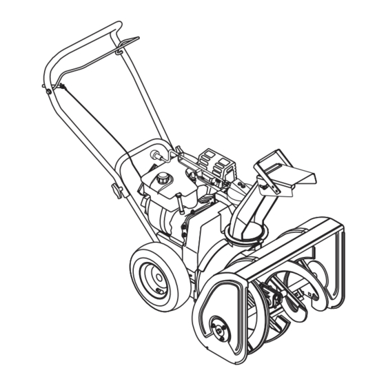
Page 4: Components View
CONTROLS AND FEATURES ENGLISH 1. Attachment Clutch Bail 2. Chute Control Lever (932102) Chute Crank (932103, 310) 3. Muffler Guard 4. Chute Deflector 5. Discharge Chute 6. Housing 7. Throttle 8. Spark Plug and Wire 9. Oil Fill and Dipstick 10. - Page 5 932103 932310 932102 Figure 1 OS1746 OS2071 OS2080 OS1911...
-
Page 6: Table Of Contents
Ariens authorized replacement part may adversely affect the performance, durability, or safety of this unit and may void the warranty. Ariens disclaims liability for any claims or damages, whether warranty, property damage, personal injury or death arising out of the use of unauthorized replacement parts. -
Page 7: Safety
Ariens Dealer for assistance. Make sure all assembly has been properly completed. NOTE: To locate your nearest Ariens Dealer, call 1-800-678-5443 or go to www.ariens.com on the internet. SAFETY ALERTS Look for these symbols to point out important safety precautions. -
Page 8: Safety Decals And Locations
SAFETY DECALS AND LOCATIONS ALWAYS replace missing or damaged Safety Decals. Refer to figure below for Safety Decal locations. 1. DANGER! ROTATING PARTS Stop engine and remove ignition key before clearing. High speed impeller rotates below discharge opening. Wait for all moving parts to stop before removing clogs or servicing. - Page 9 ASSEMBLY SAFETY RULES Read, understand, and follow all safety practices in Owner/Operator Manual before assembling. Failure to follow instructions could result in personal injury and/or damage to unit. ALWAYS remove key and/or wire from spark plug before assembly. Unintentional engine start up can cause death or serious injury.
- Page 10 Rotating impeller can cause serious injury. DO NOT unclog unit while engine is running. When leaving operator’s position for any reason, ALWAYS disengage auger, stop unit and engine, remove key and allow moving parts to stop. Before starting engine, disengage control(s). Use only approved extension cords and receptacles when starting units equipped with Electric starter.
-
Page 11: Assembly
MAINTENANCE AND SERVICE SAFETY RULES Before cleaning, removing clogs or making any inspections, repairs, etc.: disengage clutch(es), stop unit and engine, remove key, allow moving parts to stop. Allow hot parts to cool. Before tipping unit up onto housing, remove enough fuel so no spills will occur. - Page 12 Discharge Chute (932102) 1. Grease discharge chute ring if not already greased (Figure 4b). 2. Remove mounting hardware from top of engine. 3. Slide discharge chute over opening on housing and under the retaining clip. Check Attachment Clutch Cable 1. Ensure spring is connected into hole in clutch arm at rear of frame.
-
Page 13: Operation
3. Ensure Z bend end of clutch cable is connected to hole in tab on right side of clutch bail. Check Auger Gearcase Oil Check oil level in auger gearcase (see Maintenance Section). Fill Engine Crankcase IMPORTANT: Engines are shipped without oil in crankcase. -
Page 14: Filling Fuel Tank
Throttle The Throttle controls the engine speed. To increase or decrease the engine speed, adjust to: 1.Fast (normal or warm starts) 2.Part-Throttle 3.Slow (cold weather starts) 4."Stop" (engine is off) STOP OL2072 Recoil Starter Handle IMPORTANT: DO NOT let handle snap back against starter. -
Page 15: Snow Removal
5. Insert key into ignition switch and push into RUN position. DO NOT twist key after inserting it. 6. Grasp starter handle and pull rope out slowly until it pulls harder. Let rope rewind slowly. 7. Pull rope with a rapid continuous full arm stroke. -
Page 16: Maintenance
Secure unit chassis to transport vehicle. NEVER secure from rods or linkages that could be damaged. DO NOT transport machine while engine is running. WARNING: AVOID INJURY. Read and understand Maintenance and Service/Fuel Safety Rules before proceeding. SERVICE POSITION Place unit on a flat level surface. Before tipping unit up onto housing, remove enough fuel so no spills will occur. - Page 17 filler hole with unit resting on a level surface. 2. Add lubricant if required. Allow oil to drain to level of plug and replace plug. IMPORTANT: Use only Ariens special gear lubricant L-2 (Part Number 00008000). Auger Gearcase Figure 5 GENERAL LUBRICATION IMPORTANT: Wipe each fitting clean before...
-
Page 18: Attachment Drive Belt Replacement
SERVICE AND ADJUSTMENTS WARNING: AVOID INJURY. Read and understand Maintenance and Service/Fuel Safety Rules before proceeding. ATTACHMENT DRIVE BELT REPLACEMENT Remove old attachment drive belt: 1. Shut off engine, remove key, disconnect spark plug wire and allow unit to cool completely. - Page 19 Cap Screws Figure 8 ATTACHMENT CLUTCH / BRAKE ADJUSTMENT WARNING: IMPROPER ADJUSTMENT could result in unexpected movement of auger and impeller causing death or serious injury. Auger/impeller must stop within 3 seconds when attachment clutch bail is released. 1. Remove belt cover. 2.
-
Page 20: Discharge Chute
3. Deflector & Hardware Figure 10 Figure 9 SHEAR BOLTS IMPORTANT: Use only Ariens shear bolts for replacement. Use of any other type of shear bolt may result in severe damage to unit. Occasionally a foreign object may enter the... -
Page 21: Storage
AUGER EDGE REPLACEMENT Over time the rubber edges of the auger will wear. Contact your Ariens Dealer for replacement. IMPORTANT: Replace rubber edges before metal auger begins to wear. NOTE: After replacement of auger rubber edges, adjust scraper blade. See Scraper Blade Adjustment below. -
Page 22: Troubleshooting
1. Shear bolts broken. 2. Attachment clutch/brake not adjusted properly. 3. Attachment drive belt worn or damaged. Be sure to always use genuine Ariens parts to keep your Sno-Thro running like new. Part No. 53200500 03243659 03243259... -
Page 23: Specifications
Model Number Description Engine - Tecumseh Power Max - HP (Kw/min Fast Idle Speed - RPM (min Displacement - in (cc) Electric Start Fuel Tank Capacity - qt (Liters) Snow Clearing Width - in (cm) Snow Throwing Distance - ft. (m) Chute - Rotation Angle Impeller Speed - Max RPM (min Auger... -
Page 24: Warranty
Ariens Company warrants to the original purchaser that consumer products manufactured by Ariens Company will be free from defects in material and workmanship for a period of three (3) years after the date of purchase, and will repair any defect in material or workmanship, and repair or replace any defective part, subject to the conditions, limitations and exclusions set forth herein. - Page 25 (90) days following the date of purchase. Ariens Company may from time to time change the design of its products. Nothing contained in this warranty shall be construed as obligating Ariens Company to incorporate such design changes into previously manufactured products, nor shall such changes be construed as an admission that previous designs were defective.
- Page 26 Ariens Company 655 West Ryan Street P.O. Box 157 Brillion, WI 54110-0157 920-756-2141 Fax 920-756-2407 www.ariens.com...