Epson L-1000 Technical Manual
Hide thumbs
Also See for L-1000:
- User manual (136 pages) ,
- Product information (5 pages) ,
- Product support bulletin (3 pages)
Table of Contents
Advertisement
Quick Links
Advertisement
Chapters
Table of Contents

Related Manuals for Epson L-1000


Summary of Contents for Epson L-1000
- Page 1 LQ-500 L-1000 TECHNICAL MANUAL EPSON...
- Page 2 Epson America, Inc. No patent liability is assumed with respect to use of the informa- tion contained herein. While every precaution has been taken in the preparation of this book, Epson America, Inc., assumes no responsibility for errors or omissions.
- Page 3 REV.-A REVISION SHEET LQ-500/ L-1000...
- Page 4 If the Epson product has a primary AC rating different from the available power source, do not connect it to the power source. 3. Always verify that the Epson product has been disconnected from the power source before removing or replacing printed circuit boards and/or individual chips.
- Page 5 Includes a step-by-step guide for product disassembly, assembly, and adjustment. C h a p t e r 5 - Provides Epson-approved techniques for troubleshooting. C h a p t e r 6 - Describes preventive maintenance techniques and lists lubricants and adhesives required to service the equipment.
- Page 6 REV.-A TABLE OF CONTENTS CHAPTER 1. PRODUCT DESCRIPTION CHAPTER 2. PRINCIPLES OF OPERATION CHAPTER 3. OPTIONAL EQUIPMENT CHAPTER 4. DISASSEMBLY, ASSEMBLY, AND ADJUSTMENT CHAPTER 5. TROUBLESHOOTING CHAPTER 6. MAINTENANCE APPENDIX LQ-500/L-1000...
-
Page 7: Table Of Contents
REV.-A CHAPTER 1 GENERAL DESCRIPTION FEATURES..................SPECIFICATIONS................1.2.1 Hardware Specifications ............1.2.2 Firmware Specifications............INTERFACE OVERVIEW ..............1-11 DIP SWITCHES AND JUMPER SETTING ........... 1-14 1-14 1.4.1 DIP Switch Settings ............1.4.2 Jumper Setting..............1-15 1-15 SELECTYPE FUNCTION .............. - Page 8 REV.-A Character Matrix.............. 1-10 FIGURE 1-5. 1-11 Data Transmission Timing..........FIGURE 1-6. 1-16 Self-Test Printout ............FIGURE 1-7. 1-17 Hexadecimal Dump Function ..........FIGURE 1-8. 1-20 Lever Position..............FIGURE 1-9. LQ-500/ L-1000 Component Layout........1-22 FIGURE 1-10. 1-22 PBMA Main Control Board ..........
-
Page 9: General Description
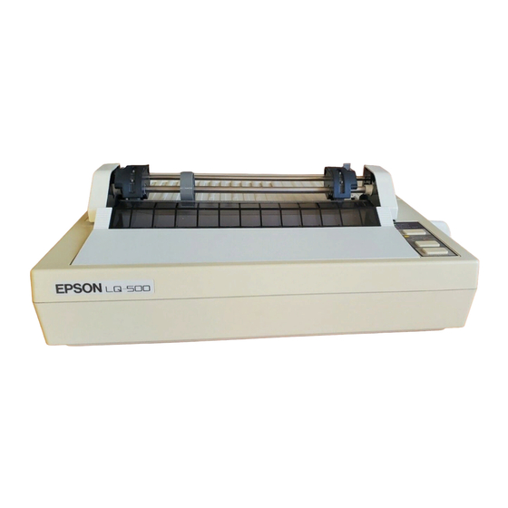
Easy handling of cut sheets with the optional cut-sheet feeder (CSF) The LQ-500/L-1000 is equipped with the standard EPSON 8-bit parallel interface. Various interface options enable users to print data from a wide variety of computers. Table l-l lists the interface options, Table l-2 lists the optional units available for the LQ-500/L-1000, and Figure l-l shows an exterior view of the LQ-500 / L-1000. - Page 10 EV .-A GENERAL DESCRIPTION (Printer Cover A) (Printer Cover B) Exterior View of the LQ-500/L-I000 Figure 1-l. LQ-500 / L-1000...
-
Page 11: Hardware Specifications
GENERAL DESCRIPTION REV.-A 1.2 SPECIFICATIONS This section describes the specifications for the LQ-500/L-1000 printer. 1.2.1 Hardware Specifications Serial, impact, dot matrix Printing Method Pin Configuration 24 wires (12 x 2 staggered, diameter 0.2 mm) Figure 1-2. Pin Configuration Feeding Method Friction feed, tractor feed (pull tractor) Line Spacing 1/6 inch, or programmable in units of 1/l80 inch... -
Page 12: Figure 1-3. Cut-Sheet Printable Area
REV.-A GENERAL DESCRIPTION Table 1-4. Continuous (Sprocket) Paper Specifications Printable Area The figure below illustrates the printable area for cut sheets. *1) 3 mm or more using 182 mm to 229 mm (7.2 in. to 9 in.) width paper. 27 mm or more using 257 mm (10.1 in.) width paper. Figure 1-3. -
Page 13: Figure 1-4. Printable Area For Continuous (Sprocket)-Feed Paper
GENERAL DESCRIPTION REV.-A *1) 13 mm or more using 101 mm to 242 mm (4 in. to 9.5 in.) width paper. 26 mm or more using 254 mm (10 in.) width paper. 2) 13 mm or more using 101 mm to 242 mm (4 in. to 9.5 in.) width paper. 24 mm or more using 254 mm (10 in.) width paper. - Page 14 REV.-A GENERAL DESCRIPTION Ink Ribbon Exclusive ribbon cartridge Type Black Color 2 million characters at 48 dots/character Reliability Dimensions of Ribbon 293 mm (width) x 34 mm (height) x 72 mm (depth) Cartridge Reliability Mean Cycles Between Failures 3 million lines (excluding printhead) (MCBF) Mean Time Between Failures 4000 POH (25% duty)
-
Page 15: Firmware Specifications
Character Set EPSON Roman (Family number: 0) Family EPSON Sans Serif (Family number: 1) EPSON Roman 10, EPSON Roman 12, EPSON Roman 15, Fonts EPSON Roman Proportional; EPSON Sans Serif 10, EPSON Sans Serif 12, EPSON Sans Serif 15, EPSON Sans Serif Proportional;... -
Page 16: Table 1-5. Printing Mode
REV.-A GENERAL DESCRIPTION Table 1-5. Printing Mode NOTES: 1. “Max.” means the value when characters of the maximum width were printed. 2. “Min.” means the value when characters of the minimum width were printed. 3. “-" means that “LQ” character set is automatically selected when proportional pitch is specified. LQ-500/ L-1000... -
Page 17: Table 1-6. Character Matrix And Character Size
GENERAL DESCRIPTION REV.-A Table 1-6. Character Matrix and Character Size NOTES: HDD is horizontal dot density in dots per inch. Face matrix and character size indicate the size of the maximum character, and this value will be changed by differences in paper, ribbon, etc. Unit ESC sp (which also can be sent as the unit followed by the character string CHR$ (&h20)) indicates the minimum length to be added to the right of the character that can be specified with the ESC sp control code. -
Page 18: Figure 1-5. Character Matrix
REV.-A GENERAL DESCRIPTION Figure 1-5. Character Matrix LQ-500/ L-1000 1-10... -
Page 19: Interface Overview
GENERAL DESCRIPTION REV.-A 1.3 INTERFACE OVERVIEW The 8-bit parallel interface, provided standard with this printer, has the following specifications: 8-bit parallel Data Format Synchronization By S pulse TROBE By BUSY and ACKNLG signal Handshaking Signal Level TTL-compatible 57-30360 (Amphenol) or equivalent Adaptable Connector Data Transmission Timing See Figure 1-6... - Page 20 REV.-A GENERAL DESCRIPTION Table 1-7. Connector Pin Assignments and Signal Functions (Cont.) NOTES: “Dir.” refers to the direction of the signal flow as viewed from the printer. “Return” denotes a twisted-pair return line. 3. The cable used must be shielded to prevent noise. All interface conditions are based on TTL levels.
-
Page 21: Table 1-8. Printer Select/Deselect Control
GENERAL DESCRIPTION REV.-A Table 1-8 shows the printer select/deselect (DC1 /DC3) control, including relations among ON-LINE, SELECT-IN input, DC1 /DC3, and interface signals. Table 1-8. Printer Select/Deselect Control NOTES: In Table 1-8, it is assumed that no ERROR status exists other than that attributable to OFF-LINE mode. Once the printer is deselected by the DC3 code, the printer will not revert to the selected state unless the DC1 code is input again. -
Page 22: Dip Switches And Jumper Setting
REV.-A GENERAL DESCRIPTION 1.4 DIP SWITCHES AND JUMPER SETTING This section describes the DIP switch selections and the jumper setting for the LQ-500/L-1000 printer. 1.4.1 DIP Switch Settings slot cover and function as shown switches for the printer are located inside the ROM cartridge in Tables 1-9 through 1-13. -
Page 23: Jumper Setting
GENERAL DESCRIPTION REV.-A Table 1-12. Font Selection Font Roman Sans Serif Slot Draft Table 1-13. Character Pitch Selection Character Pitch 10 CPI 15 CPI Proportional 1.4.2 Jumper Setting Jumper 6, which is user-selectable, is located inside the ROM cartridge slot cover. If the jumper is connected, signal is fixed to LOW, and DC1 /DC3 printer select control is ignored. -
Page 24: Operating Instructions
REV.-A GENERAL DESCRIPTION 1.6 OPERATING INSTRUCTIONS This section describes the self-test and hexadecimal dump functions and also includes the error states, printer initialization, and the buzzer operation. 1.6.1 Self-Test To begin printing the self-test using Draft mode, turn the printer ON while pressing the LINE-FEED button. To begin printing the self-test using the Letter Quality (LQ) mode, turn the printer power ON while pressing FORM-FEED. -
Page 25: Figure 1-8. Hexadecimal Dump Function
GENERAL DESCRIPTION REV.-A 1.6.2 Hexadecimal Dump Function The printer enters HEX-DUMP mode when it is powered on while the LINE-FEED and FORM-FEED buttons are pressed down. In HEX-DUMP mode, the hexadecimal representation of the input data is printed out, along with corresponding ASCII characters. -
Page 26: Bit-Image Printing
REV.-A GENERAL DESCRIPTION 1.6.3 Bit-Image Printing This printer has four standard print densities, listed below in dots per inch (dpi): 120 dpi (including half dots): Triple speed 180 dpi (including half dots): Double speed 240 dpi (including half dots): 1.5 speed 360 dpi (including half dots): Normal speed The firmware, however, implements the print densities as shown in Table 1-14 Table 1-14. -
Page 27: Error Conditions
GENERAL DESCRIPTION REV.-A 1.6.4 Error Conditions If any of the following error conditions is detected, the printer automatically enters OFF-LINE mode. 0 Home position is not detected at printer mechanism initialization. e Home position is detected during printing. 0 ON-LINE is pressed, and the printer enters OFF-LINE. A paper-out signal is detected and forms-override is finished. -
Page 28: Default Values
REV.-A GENERAL DESCRIPTION 1.6.7 Default Values When the printer is initialized, the following default values or functions are set: Current paper position becomes top-of-form position Page Position Left and Right Margins Released Line Spacing 116 inch Cleared Vertical Tabs Horizontal Tabs Every 8 characters (relative) VFH Channel Channel 0... -
Page 29: Printer Protection For Heavy-Duty Printing
GENERAL DESCRIPTION REV.-A. 1.6.9 Printer Protection for Heavy-Duty Printing This printer has “printhead protection” to safeguard the printhead from overheating or from voltage dropping to the head driver. If head temperature exceeds upper limit value, then printing is automatically stopped until head temperature has dropped to a certain value to resume printing. -
Page 30: Main Components
GENERAL DESCRIPTION REV.-A 1.7 MAIN COMPONENTS The main components of the LQ-500/L-1000 printer are designed for easy removal and replacement to main- tain/repair the printer. The main components are: 1) PBMA board: The main control board; the CPU on this board controls all main functions 2) PEBPNL board: The control panel board. -
Page 31: Figure 1-12. Pebpnl Control Panel Board
GENERAL DESCRIPTION REV.-A 1.7.2 PEBPNL Board The PEBPNL board is the LQ-500/L-1000 control panel, which contains the indicator LEDs, switches, and buzzer. Figure 1-12. PEBPNL Control Panel Board 1.7.3 PEBFIL Board The PEBFIL board eliminates noise from the AC line to the printer and from the printer to the outer line. The fuse used on this board prevents overheating. -
Page 32: Printer Mechanism (M-5410)
REV.-A GENERAL DESCRIPTION 1.7.4 Transformer This transformer changes the input AC from the filter circuit into 26 VAC and 12 VAC in order to supply the necessary voltages to the control circuit board. (240 V Version) (220 V Version) (120 V Version) Figure 1-14. -
Page 33: Figure 1-16. Housing
GENERAL DESCRIPTION REV.-A 1.7.6 Housing LQ-500/L-1000 housing consists of the upper and lower cases. The upper case houses the control panel. The lower case contains the printer mechanism and the main control board. The printer cartridge is easily removable and can be replaced simply by lifting the upper case. Figure 1-16. - Page 34 REV.-A CHAPTER 2 PRINCIPLES OF OPERATION OVERVIEW ..................Summary of Connectors............2.1.1 2.1.2 Overview of Printer Mechanism Operation......2-3 2.1.2.1 Sensors............... 2.1.2.2 Motors ..............Printhead ............2.1.2.3 2.1.3 Overview of Circuitry............2.1.4 Firmware Overview ............. PRINCIPLES OF OPERATION............2.2.1 Power Supply Circuit ............
- Page 35 REV.-A Paper-Feed Motor Drive Circuit ......2-51 2.2.6.3 Paper-Feed Motor Software Control....... 2-52 2.2.6.4 2-54 Printhead ................2.2.7 Printhead Printing Operation ......... 2-54 2.2.7.1 Printhead Specifications ........2-55 2.2.7.2 Printhead Drive Circuit Block Diagram....2-55 2.2.7.3 Gate Array E05A02LA Operation in Printhead 2.2.7.4 2-56 Drive Circuit ............
- Page 36 REV.-A Output Transistor Drive Waveform ........2-17 FIGURE 2-20. 2-18 +24 V Regulator Circuit ........... FIGURE 2-21. Constant-Voltage Control (+ 24 VDC) ........ 2-19 FIGURE 2-22. 2-19 Over-Current Protection (OCP) .......... FIGURE 2-23. 2-20 + 12 VDC Circuit ............. FIGURE 2-24. 2-21 Vx Voltage Circuit ............
-
Page 37: List Of Tables
REV.-A 2-65 Input Buffer Structure............FIGURE 2-58. 2-65 Line Buffer Structure ............FIGURE 2-59. 2-66 Image Buffer Structure ............. FIGURE 2-60. 2-66 Queue Buffer Structure............ FIGURE 2-61. Download Buffer Structure..........2-67 FIGURE 2-62. 2-68 Main Routine..............FIGURE 2-63. -
Page 38: Overview
PRINCIPLES OF OPERATION REV.-A 2.1 OVERVIEW This chapter describes the signals at the various connectors that link the primary Components of the LQ-500/L-1000, including the printer mechanism, power supply circuits, and control circuits. The chapter also describes the operation of the printer’s circuitry and printer mechanism. 2.1.1 Summary of Connectors The interconnection of the primary components is shown in Figure 2-1. - Page 39 PRINCIPLES OF OPERATION REV.-A Figure 2-1. Cable Connections LQ-500/L-1000...
-
Page 40: Overview Of Printer Mechanism Operation
PRINCIPLES OF OPERATION REV.-A 2.1.2 Overview of Printer Mechanism Operation The Model 5410 printer mechanism is a serial, impact, dot-matrix printer that prints at 180 dots per inch (DPI) in both the horizontal and vertical directions. Figure 2-2 shows a block diagram of the Model 5410 printer mechanism. -
Page 41: Sensors
REV.-A PRINCIPLES OF OPERATION 2.1.2.1 Sensors The printer mechanism is equipped with the following sensors: Paper-End (PE) Sensor Home-Position (HP) Sensor Thermal Sensor (Printhead Temperature) Paper-End Sensor (PE Sensor) Figure 2-3 shows the paper-end sensor. This sensor switch is ON when paper runs out. Paper-out state - ON + LOW level Paper present - OFF - HIGH level Figure 2-3. - Page 42 PRINCIPLES OF OPERATION REV.-A Thermal Sensor (Printhead Temperature Detection) The thermal sensor in the printhead monitors printhead temperature. If head temperature exceeds the upper limit value, then printing is automatically stopped until head temperature drops to a certain value before resum- ing printing.
-
Page 43: Motors
REV.-A PRINCIPLES OF OPERATION 2.1.2.2 Motors This printer has the following motors: Carriage motor (stepper motor) Paper-feed motor (stepper motor) Carriage Motor The carriage motor is used to move the carriage right and left along the platen. This unit employs a 4-phase, 48-step motor using either 1-2 or 2-2 phase excitation and is controlled by an open-loop system. -
Page 45: Firmware Overview
REV.-A PRINCIPLES OF OPERATION 2.1.4 Firmware Overview This printer has a µPD7810HG CPU with 64K bytes of address space. Figure 2-8 shows a memory map of this address space. NOTE: CG = character generator. GA = gate array. Figure 2-8. Memory Map (64K Bytes) LQ-500/ L-1000... -
Page 46: Principles Of Operation
REV.-A PRINCIPLES OF OPERATION 2.2 PRINCIPLES OF OPERATION This section describes the operation of each component. 2.2.1 Power Supply Circuit The paragraphs below provide details of power supply circuit operations. 2.2.1.1 Power Supply Circuit Block Diagram 120/220/240 VAC are applied to the step-down transformer via the filter circuit to create 26 VAC and 12 VAC, which are then input to the power supply circuit on the main board. - Page 47 REV.-A PRINCIPLES OF OPERATION Table 2-2. Power Supply Applications 2-10 LQ-500 / L- 1000...
-
Page 48: Chopper-Type Switching Regulator Circuit
REV.-A PRINCIPLES OF OPERATION 2.2.1.2 Chopper-Type Switching Regulator Circuit A chopper-type switching regulator is employed in the power supply circuit. Operation of the step-down circuit is as follows: Figure 2-10. Step-Down Circuit Figure 2-10 shows the chopper-type, step-down switching regulator circuit. When the transistor is ON, voltage Vi is applied to coil L and capacitor C, and load current flows. -
Page 49: Filter Circuit
REV.-A PRINCIPLES OF OPERATION 2.2.1.3 Filter Circuit The AC line voltage passes through the power switch, then is input to the filter circuit. A fuse, F1, is used on the PEBFIL board. The filter circuit attenuates external noise and inhibits noise generated in the printer from going out via the AC line. -
Page 50: Rectifier And Smoothing Circuit
PRINCIPLES OF OPERATION REV.-A 2.2.1.5 Rectifier and Smoothing Circuit The 26 VAC from the secondary coil of the transformer are full-wave rectified by diode bridge DB1, and con- verted to approximately 36 VDC by smoothing capacitor C40. The + 24 VDC and + 5 VDC voltages are con- verted from this DC voltage, which is used as the power supply voltage for the switching regulator IC at the next stage. - Page 51 REV.-A PRINCIPLES OF OPERATION 2.2.1.6 + 5 V Regulator Circuit Figure 2-15 shows the +5 VDC regulator circuit. An NJM2355 switching regulator IC is used for constant- frequency pulse-width modulation. The circuit shown above employs an NJM2355 configured as a chopper- style switching regulator circuit.
- Page 52 PRINCIPLES OF OPERATION REV.-A AMP 1 in the IC is an error amplifier used to monitor the output voltage. Figure 2-17 shows the constant-voltage control circuit. Pin 1 of the IC provides a 5 V reference output (Vref), which is applied to the negative terminal of AMP 1.
-
Page 53: Pulse-Width Modulation (Pwm) Circuit
REV.-A PRINCIPLES OF OPERATION 2.2.1.7 Pulse-Width Modulation (PWM) Circuit Figure 2-19 shows the internal circuit of the NJM2355 IC. The PWM comparator operates as follows: In circuit 1 the output from AMP 1 flows into the negative terminal of comparator 1, and the outputs from AMP 2 and AMP 3 in circuit 2 flow into the negative terminal of PWM comparator 2 without wired OR. - Page 54 REV.-A PRINCIPLES OF OPERATION As shown in Figure 2-20, when the potential at the NJM2355 is lower than the preset voltage or current value, it is controlled by the dead-time control voltage. When it exceeds the preset value, it is controlled by the error amplifier to keep it lower than the preset value.
-
Page 55: Vdc Regulator Circuit
REV.-A PRINCIPLES OF OPERATION 2.2.1.8 + 24 VDC Regulator Circuit Figure 2-21 shows the + 24 V regulator circuit. The + 24 VDC regulator circuit has almost the same function and employs the same oscillation circuit as the +5 VDC regulator circuit. Here, the error amplifier AMP 2 is used for over-current control, and AMP 3 for constant-voltage control. - Page 56 PRINCIPLES OF OPERATION REV.-A The negative terminal of AMP 3 receives (5 V). Consequently, the voltage applied to the positive terminal is adjusted to 5 V. Therefore, based on Figure 2-22, the output voltage is set to the following value: Figure 2-22.
-
Page 57: Vdc Supply Circuit
REV.-A PRINCIPLES OF OPERATION 2.2.1.9 + 12 VDC Supply Circuit The 12 VAC from the transformer is half-wave rectified by diode D19 and is converted to + 12 VDC. As shown by Figure 2-24, the half-wave rectified voltages pass through the capacitor smoothing circuit so that the ripple is small, and the average DC voltage rises when no load current flows and drops as load current increases. -
Page 58: Vx Voltage Supply Circuit
REV.-A PRINCIPLES OF OPERATION 2.2.1.10 Vx Voltage Supply Circuit When the +24 V power supply line reaches 18.6 V (18 V + 0.6 V), transistors Q25 and Q26 turn on and Vx ( + 5 V) is output. On the other hand, if the + 24 V power supply line drops to 18.6 V or less, Q25 and Q26 turn off and the Vx voltage is shut off. -
Page 59: Reset Circuit
REV.-A PRINCIPLES OF OPERATION 2.2.2 Reset Circuit Figure 2-26 shows the reset circuit. The RESET signal generated here is sent to the RESET terminal of CPU µPD781 OHG (46) and to connector CN2-13 (optional interface) as a hardware initialization signal. The RESET signal is output from the circuit when any of the following occurs: 0 Power is turned on or off. - Page 60 PRINCIPLES OF OPERATION REV.-A The rising edge of the Vx voltage cancels the RESET signal after a delay of time constant = R69 x C26 produced by the integration circuit of resistor R69 and capacitor C26. The falling edge of the Vx voltage ac- tivates a RESET signal by discharging capacitor C26 via diode D14.
- Page 61 REV.-A PRINCIPLES OF OPERATION Module Installation or Removal Figure 2-28 shows the RESET pulse generation process that occurs when a ROM cartridge is mounted. Numbers in parentheses below correspond to circled numbers in the figure. After the ROM cartridge is mounted, the LOW signal flows into the CAR terminal of the gate array (6C), and a LOW signal is correspondingly output from the DISC terminal and RESET is output from the ROUT terminal.
- Page 62 REV.-A PRINCIPLES OF OPERATION When the ROM cartridge is removed (see Figure 2-29), the CAR terminal of the gate array (6C) receives a HIGH signal. Then the DISC terminal outputs a LOW signal, and the ROUT terminal outputs a RESET signal. The remainder of the sequence is similar to that when a ROM cartridge is mounted, so please refer to the preceding page.
-
Page 63: Firmware Operation At Reset
REV.-A PRINCIPLES OF OPERATION 2.2.3 Firmware Operation at Reset After being reset, the CPU executes the initialization program from address 0000 hex. When this program has completed normally, the CPU enters the standby state and waits for data. Figure 2-30 shows the initialization program flowchart. - Page 64 REV.-A PRINCIPLES OF OPERATION Figure 2-30. Initialization Program Flowchart (Cont.) L Q - 5 0 0 / L - 1 0 0 0 2 - 2 7...
- Page 65 REV.-A PRINCIPLES OF OPERATION Figure 2-30. Initialization Program Flowchart (Cont.) LQ-500I 2 - 2 8 L-1000...
-
Page 66: Address Decorder And Bank Register
PRINCIPLES OF OPERATION REV.-A 2.2.4 Address Decoder and Bank Register This section describes the address decoder and bank register. Address Decoder This unit includes an address decoder in gate array E01A05KA (6C). The address decoder outputs a chip-select signal to the internal PROM (3C), external PROM, 4MCG (5C), 1 MCG (2C), external CG, RAM (2C), HEAD gate array (7A) via address lines AB12 through AB15 and bank lines 7 and 6 (in the gate array). - Page 67 REV.-A PRINCIPLES OF OPERATION Bank Register This unit has a bank register in gate array EOlA05KA (6C). The bank lines are set by writing to address FO02 hex., and they can be checked by reading the same address. Table 2-3 shows the relationship between data bits and bank lines.
-
Page 68: Carriage Operation
PRINCIPLES OF OPERATION REV.-A 2.2.5 Carriage Operation This section describes the carriage. 2.2.5.1 Carriage Mechanism The carriage mechanism includes the printhead, the carriage, the timing belt, the carriage motor, and the platen. Figure 2-32 shows the carriage mechanism. The timing belt is connected into the bottom of the carriage. This belt is driven by the carriage motor and moved via the belt-driven pulley. - Page 69 REV.-A PRINCIPLES OF OPERATION 2.2.5.3 Carriage Drive Circuit Block Diagram Figure 2-33 shows a block diagram of the carriage motor drive circuit. In this circuit, the phase switching for the carriage motor is not directly executed by the CPU, but by the gate array (6C) using pulses from the CPU. STK-6981 B is employed to drive the carriage motor using a stabilized current.
-
Page 70: Gate Array Eola05Ka Operation In Carriage Motor Drive Circuit
PRINCIPLES OF OPERATION REV.-A 2.2.5.4 Gate Array EOlA05KA Operation in Carriage Motor Drive Circuit The phase switching for the carriage motor (stepper motor) is performed by gate array EOlA05KA (6C). This gate array first sets the excitation system (2-2 phase or 1-2 phase) and rotation direction (clockwise Or counterclockwise). - Page 71 REV.-A PRINCIPLES OF OPERATION The carriage motor control port of the gate array is assigned to address FO03 hex. Control commands for the carriage motor (via the gate array) are listed in Table 2-4. Table 2-4. Control Commands When power is turned on (CW = clockwise;...
-
Page 72: Carriage Motor Drive Circuit
PRINCIPLES OF OPERATION REV.-A 2.2.5.5 Carriage Motor Drive Circuit The LQ-500 employs the STK-69816, which is a hybrid IC used to drive stepper motors. STK-6981B (IC8C) drives the stepper motor with a constant current. The value of the current is determined by an external voltage level. - Page 73 REV.-A PRINCIPLES OF OPERATION NOTE: Phase AB is equivalent to the above. Figure 2-36. STK-6981 B Circuit Diagram 2-36 LQ-500/ L-1000...
- Page 74 PRINCIPLES OF OPERATION REV.-A Reference Voltage Generation Circuit Figure 2-37 shows the reference voltage generation circuit and Table 2-5 shows the reference voltage. Figure 2-37. Reference Voltage Generation Circuit Table 2-5. Reference Voltage LQ-500/ L-1000 2-37...
- Page 75 REV.-A PRINCIPLES OF OPERATION Constant Current Drive Circuit The carriage motor-drive current is given by the following equation: I = VrCD/R79 = VrCD/1.2 ohms When the carriage stops, port PB5 of the CPU is set HIGH, the input to the chopping circuit becomes 0 V, and current is applied from the + 5 V line to the motor via resistor R1 and diode D1.
- Page 76 PRINCIPLES OF OPERATION REV.-A Table 2-6. Current Values for Reference Voltages With positive feedback through R9, a hysteresis, whose upper bound is the reference voltage, is generated in the comparator of ICl. The comparator works as a Schmitt trigger, which senses a difference only when the feedback (inverse terminal) is slightly larger or smaller than the hysteresis level.
- Page 77 PRINCIPLES OF OPERATION REV.-A Figure 2-40. Schmitt Trigger Circuit 2-40 LQ-500/L-1000...
-
Page 78: Carriage Motor Software Control
REV.-A PRINCIPLES OF OPERATION 2.2.5.6 Carriage Motor Software Control This section describes the carriage motor software control. Excitation System The excitation system is determined by the firmware and is executed in accordance with the carriage speed, as shown in Table 2-7. The motor drive sequence for each excitation system is shown in Tables 2-8 and 2-9. Table 2-7. - Page 79 REV.-A PRINCIPLES OF OPERATION Table 2-9. Drive Sequence (1-2 Excitation) Since a stepper motor is used for the carriage motor, it is possible to hold at any position and switch printing direction. The carriage motor control system is an open-loop system which switches the phases in accordance with set speeds.
- Page 80 REV.-A PRINCIPLES OF OPERATION Table 2-10. Chopping Current The times for constant speed, acceleration control, and deceleration control are shown below. The a marks in the acceleration and deceleration columns control items in the tables and indicate switching times from Al to A2 or 62 to B1.
- Page 81 REV.-A PRINCIPLES OF OPERATION Table 2-12. Acceleration Time Data (2-2 Excitation) Table 2-13. Deceleration Time Data (2-2 Excitation) 2-44 LQ-500/ L-1000...
- Page 82 PRINCIPLES OF OPERATION REV.-A Table 2-14. Acceleration Time Data (1-2 Excitation) 2-45 LQ-500/L-1000...
- Page 83 REV.-A PRINCIPLES OF OPERATION Table 2-15. Deceleration Time Data (1-2 Excitation) 2-46 L Q - 5 0 0 / L - 1 0 0 0...
- Page 84 PRINCIPLES OF OPERATION REV.-A Home-Position Seek The control that causes the carriage to move to the home position when the power is turned on is called home- position seek. Figure 2-43 shows the home-position seek operation. After power is applied, the printer executes 2-2 phase excitation for 20 or 30 ms and checks the HOME signal, regardless of the phase switching timing.
- Page 85 REV.-A PRINCIPLES OF OPERATION Printing Area The printing area is defined as starting 22 phase switching times after the home position. Figure 2-44. Printing Area and Printing Timing Abnormal Carriage Operation This unit does not employ a print timing signal (PTS) sensor and cannot detect abnormal carriage operation. Therefore, no error occurs even if carriage movement is prevented by external forces.
-
Page 86: Paper Feed
REV.-A PRINCIPLES OF OPERATION 2.2.6 Paper Feed This section describes the paper-feed operation. 2.2.6.1 Paper-Feed Mechanism Operation The paper-feed mechanism operates by friction feed for cut sheets and by the sprocket-feed method for fanfold paper. Friction-Feed Operation The paper is held against the platen by two paper-feed rollers and by the printer cover. At this time, the paper- feed motor is driven to rotate the platen gear, via the paper-feed reduction gear, in the direction shown in Figure 2-45. - Page 87 REV.-A PRINCIPLES OF OPERATION Sprocket-Feed Operation When using the sprocket-feed method, set the holes in the paper over the sprocket pins along the sprocket wheel. The paper-feed motor is driven to rotate the gears, via the pinion on the shaft of the motor, in the direc- tion shown in Figure 2-46.
-
Page 88: Paper-Feed Motor Specifications
REV.-A PRINCIPLES OF OPERATION 2.2.6.2 Paper-Feed Motor Specifications Paper-feed motor specifications are as follows: 4-phase, 48-pole stepper motor Type Drive Voltage VDC + 10% Coil Resistance ohms f at 25 degrees C Phase Excitation 2-2 phase excitation Current Maximum, 1.1 A (Rush Current) Driving: 0.30 A (typical) Holding: 0.06 A f 20 mA Driving Frequency... -
Page 89: Paper-Feed Motor Software Control
REV.-A PRINCIPLES OF OPERATION 2.2.6.4 Paper-Feed Motor Software Control The paper-feed motor is a 48-pole stepper motor and is open-loop controlled. Paper is fed 1/180th inch for each step when the paper-feed motor is driven by the 2-2 phase excitation system. Table 2-16 shows the paper-feed motor excitation system. - Page 90 PRINCIPLES OF OPERATION REV.-A Table 2-17. Setting Time NOTE: If steps are less than 10, the speed is neither accelerating nor decelerating LQ-500/ L-1000 2-53...
-
Page 91: Printhead
REV.-A PRINCIPLES OF OPERATION 2.2.7 Printhead This section describes printhead operation. 2.2.7.1 Printhead Printing Operation The dot-wire operation during printing is as follows: when the head-driving coil for a dot wire is energized, the actuating plate engaged with the dot wire at one end is attracted to the iron core and drives the dot wire toward the platen. -
Page 92: Printhead Specifications
REV.-A PRINCIPLES OF OPERATION 2.2.7.2 Printhead Specifications Printhead specifications are as follows: Solenoids 24 solenoids Wire Diameter 0.02 mm Pin Arrangement 12 x 2, staggered Drive Voltage 24 VDC k 10% Coil Resistance 16 f 10% at 25 degrees C Driving Pulse Width 415 µs to 435 µs Solenoid Drive Frequency... -
Page 93: Gate Array E05A02La Operation In Printhead Drive Circuit
REV.-A PRINCIPLES OF OPERATION 2.2.7.4 Gate Array E05A02LA Operation in Printhead Drive Circuit The E05A02LA gate array includes circuitry to interface the CPU and the printhead. This general-purpose gate array has special commands that lighten the load on the CPU when outputting printhead data. Figure 2-51 is a block diagram of the E05A02LA gate array. - Page 94 PRINCIPLES OF OPERATION REV.-A Table 2-18. E05A02LA Gate Array Functions NOTE: When HPW setting is invalid, the HPW output will be in the open-drain ON state independent of the HPW input. The drive pulse is input to the HPW terminal. 2-57 LQ-500/ L-1000...
-
Page 95: Printhead Drive Circuit
REV.-A PRINCIPLES OF OPERATION 2.2.7.5 Printhead Drive Circuit The drive pulse width is adjusted using CPU port PC6. The Vx voltage is used to pull up the output signals from the gate array in order to prevent printhead malfunctions. Figure 2-52. Printhead Drive Circuit Figure 2-53. -
Page 96: Printhead Software Control
REV.-A PRINCIPLES OF OPERATION 2.2.7.6 Printhead Software Control During operation at 900 PPS, one print cycle is performed at each phase switching step to meet the specifica- tions of the printhead (solenoid drive frequency: 900 Hz). The drive pulse width is adjusted by using an A/D converter to detect the drive voltage, and is kept within the area shown by the oblique lines in Figure 2-55. -
Page 97: A/D Converter Circuit
PRINCIPLES OF OPERATION REV.-A 2.2.8 A/D Converter Circuit Figure 2-56 shows the A/D converter circuit. The functions of this converter are as follows: 0 Monitors the +24 V line to determine the drive pulse width for the printhead. 0 Monitors the temperature (the resistance value) of the printhead. 0 Reads the initial DIP switch settings. - Page 98 PRINCIPLES OF OPERATION REV.-A Table 2-19 shows the relationship between the scan lines and DIP switches. Table 2-19. Scan Lines and DIP Switches LQ-500/L-1000 2-61...
-
Page 99: Host Interface
REV.-A PRINCIPLES OF OPERATION 2.2.9 Host Interface The host interface circuit is shown in Figure 2-57. STROBE pulses from the host computer pass through the low-pass filter, consisting of R32 and C21, and flow into the STRB terminal. These pulses latch the parallel data and set the BUSY signal HIGH, so that subsequent data transfer is inhibited. - Page 100 PRINCIPLES OF OPERATION REV.-A Table 2-20. Control Commands LQ-500/ L-1000 2-63...
- Page 101 REV.-A PRINCIPLES OF OPERATION Table 2-20. Control Commands (Cont.) NOTES: 1. Hardware BUSY is automatically reset by reading address FOOO hex. This bit determines whether hardware BUSY is activated by the rising or falling edge of STRB. Hardware BUSY is activated by the rising or falling edge of the STRB signal. The final output of the BUSY signal is the conjunction of the hardware BUSY and software BUSY.
-
Page 102: Buffer And Data Flow
PRINCIPLES OF OPERATION REV.-A 2.2.10 Buffer and Data Flow This section describes the buffer and data fiow. 2.2.10.1 Buffer There are 5 kinds of buffers: input, line, image, queue, and download. The structure of each buffer is described as follows: Input Buffer Figure 2-58 shows the input buffer structure. - Page 103 REV.-A PRINCIPLES OF OPERATION Image Buffer The image buffer has two lines at 360 DPI (including half dots). One line is used for data output, and the other is used for developing the image data. The image data is output when an interruption is made by the SOFTI. Figure 2-60 shows the image buffer structure.
- Page 104 REV.-A PRINCIPLES OF OPERATION Download Buffer The download buffer has a capacity of 6K bytes. Figure 2-62 shows the download buffer structure. Figure 2-62. Download Buffer Structure LQ-500 / L-1000 2-67...
-
Page 105: Data Flow
REV.-A PRINCIPLES OF OPERATION 2.2.10.2 Data Flow Data flow is shown in the main routine (Figure 2-63) and the printing routine (Figure 2-64). The main routine analyzes commands, develops data into image data, and controls interruption (prohibition, permission, opera- tion). Interruption includes data input from the host computer, paper-feed operation, printing output, and the refresh operation. - Page 106 REV.-A PRINCIPLES OF OPERATION Figure 2-64. Printing Routine LQ-500/L-1000 2-69...
-
Page 107: Ribbon-Feed Mechanism
REV.-A PRINCIPLES OF OPERATION 2.2.11 Ribbon-Feed Mechanism The ribbon-feed mechanism consists of the ribbon cartridge and the ribbon-feed section. The ribbon-driving gear always turns counterclockwise, via the gear trains shown in Table 2-21, irrespective of the direction of the timing belt. Table 2-21. -
Page 108: Table 1-1. Interface Options
REV -A CHAPTER 3 OPTIONAL EQUIPMENT OPTIONS AVAILABLE FOR THE LQ-500/L-1000........ 3-1 INTERFACE OPTIONS..............3.2.1 Model 8143 Serial interface Operation ........FONT MODULE (TOMS BOARD)............LIST OF TABLES TABLE 3-1. Optional Interfaces ............TABLE 3-2. Jumper Settings .............. TABLE 3-3. - Page 109 REV.-A OPTIONAL EQUIPMENT 3.1 OPTIONS AVAILABLE FOR THE LQ-500/L-1000 This chapter describes the options available for the LQ-500/L-1000. 3.2 INTERFACE OPTIONS The LQ-500/L-1000 can use the Model 8100 series optional interface. The main interfaces are listed in Table 3-1. LQ-500 / L-1000...
- Page 110 REV.-A OPTIONAL EQUIPMENT 3.2.1 Model 8143 Serial Interface Operation This printer has the capability to support the Model 8143 serial interface board as an option under RS232C and 20mA neutral current loop. Specifications Asynchronous Synchronization to 19200 BPS* Bit rate Word length 1 bit Start bit...
- Page 111 OPTIONAL EQUIPMENT REV.-A Table 3-3. DIP Switch Settings Table 3-4. Bit Rate Settings NOTE: In current loop operation, normal data transfer cannot be guaranteed at a bit rate greater than 1200 BPS. Handshaking Timing This printer outputs the X-OFF code and/or REV signal (polarity can be selected by jumper setting) to indicate “not ready to receive data”...
- Page 112 REV.-A OPTIONAL EQUIPMENT 3.3 FONT MODULE (TOMS BOARD) The font module provides a wide range of optional fonts. Font modules for LQ-800/1000 printer can be used with this printer also. Table 3-5 shows the list of optional font modules. Table 3-5. Optional Font Module List LQ-500/ L-1000...
-
Page 113: Pbma Board
REV.-A CHAPTER 4 DISASSEMBLY, ASSEMBLY, AND ADJUSTMENT GENERAL REPAIR INFORMATION ......... . . 4-1 DISASSEMBLY AND ASSEMBLY . - Page 114 REV.-A LIST OF FIGURES Printhead Removal ............FIGURE 4-1. Upper Case Removal 1............. FIGURE 4-2. Upper Case Removal 2............. FIGURE 4-3. Control Panel Removal ............. FIGURE 4-4. PBMA Board Removal............FIGURE 4-5. PEBFIL Board Removal ............ FIGURE 4-6.
- Page 115 REV.-A Carriage Guide Shaft Lever Movement ......4-24 FIGURE 4-36. 4-24 Platen Gap Adjustment Positions........FIGURE 4-37. 4-27 Test Pattern Printing (Draft Mode) ........FIGURE 4-38. 4-28 Test Pattern Printing (LQ Mode) ........FIGURE 4-39. LIST OF TABLES Repair Tools ..............TABLE 4-1.
-
Page 116: General Repair Information
DISASSEMBLY, ASSEMBLY, AND ADJUST’MENT REV.-A 4.1 GENERAL REPAIR INFORMATION This chapter describes the disassembly, assembly, and adjustment procedures for replacing any of the main components of the LQ-500/L-1000. The tools and measuring instruments listed in Tables 4-l and 4-2 are recommended for use when disassembl- ing and repairing the printers. - Page 117 REV.-A DISASSEMBLY. ASSEMBLY, AND ADJUSTMENT All small parts are described using the following abbreviations. Table 4-3. List of Abbreviations for Small Parts Table 4-4. Form and Abbreviated Part Name of Screw LQ-500/L-1000...
-
Page 118: Disassembly And Assembly
DISASSEMBLY, ASSEMBLY, AND ADJUSTMENT REV.-A 4.2 DISASSEMBLY AND ASSEMBLY This chapter describes the disassembly of the LQ-500/L-1000. Assembly can be performed simply by revers- ing the order of disassembly. Special notes for assembly are given as “ASSEMBLY POINTS.” For assembly and disassembly procedures which require adjustment, the necessary adjustment is indicated as “ADJUSTMENT REQUIRED.”... - Page 119 DISASSEMBLY, ASSEMBLY, AND ADJUSTMENT REV.-A 4.2.2 Removal of Cases This section describes upper case and control panel (PEBPNL) removal. 4.2.2.1 Upper Case Removal Remove the sheet guide unit, printer cover, ROM cartridge slot cover, and paper guide. Remove the sheet guide unit, printer cover, ROM cartridge slot cover, and paper guide. Insert a standard screwdriver into the two holes at the front of the lower case, unlock the notches Insert a standard screwdriver into the two holes at the front of the lower case, unlock the notches , then...
-
Page 120: Control Panel (Pebpnl Board) Removal
DISASSEMBLY, ASSEMBLY, AND ADJUSTMENT REV.-A 4.2.2.2 Control Panel (PEBPNL Board) Removal Remove the upper case (refer to Section 4.2.2.1). Turn the upper case over, push in the two notches securing the control panel to the upper case, and remove the control panel from the upper case. WARNING When mounting and removing the control panel, be careful not to damage the FPC of the control panel with the FPC guide of the upper case. - Page 121 REV.-A DISASSEMBLY, ASSEMBLY, AND ADJUSTMENT Figure 4-5. PBMA Board Removal Remove the two CTBB screws (M3 x 5) securing the PBMA board to the base plate. Using a screwdriver, loosen the six bent tabs for the lower case, which secure the PBMA board to the lower case and remove the PBMA board.
-
Page 122: Pebfil Board Removal
DISASSEMBLY, ASSEMBLY, AND ADJUSTMENT REV.-A 4.2.3.2 PEBFIL Board Removal Remove the upper case (refer to Section 4.2.2.1). Disconnect connector CNl on the PEBFIL board, which connects the transformer to the PEBFIL board. Remove the CBO (M4 x 8) screw securing the ground terminal of the PEBFIL board. Remove the CTPS(0) (M3 x 6) screw securing the PEBFIL board to the base plate. -
Page 123: Removal Of Printer Mechanism
REV.-A DISASSEMBLY, ASSEMBLY, AND ADJUSTMENT 4.2.4 Removal of Printer Mechanism This section describes the removal of the platen unit, paper guide, and printer mechanism. Before removing the printer mechanism, take off the platen unit and the paper guide so that the printer mechanism can be removed quickly and easily. -
Page 124: Removal Of Printer Mechanism
DISASSEMBLY, ASSEMBLY, AND ADJUSTMENT REV.-A Disconnect the cable from connector CN9 on the PBMA board. Unlock the two notches of the paper guide by pushing them toward the front from the back of the printer mechanism, and remove the paper guide. Figure 4-10. - Page 125 REV.-A DISASSEMBLY, ASSEMBLY, AND ADJUSTMENT Figure 4-11. Printer Mechanism Removal Loosen tabs 1 and 2, and lift the left side of the frame 1 cm from the lower case. Loosen tab 3, and lift the left side of the frame 5 more cm from the lower case. it from tabs 4 Slide the printer mechanism in the direction shown by the arrow in Figure 4-11 to remove and 5.
-
Page 126: Disassembly Of Printer Mechanism
DISASSEMBLY, ASSEMBLY, AND ADJUSTMENT REV.-A 4.2.5 Disassembly of Printer Mechanism This section describes the removal of each component from the printer mechanism. Refer to Figure A-26, Printer Mechanism Exploded Diagram, and Table A-10, Component Name List. 4.2.5.1 Paper-Feed Mechanism Removal Remove the printer mechanism (refer to Section 4.2.4). - Page 127 REV.-A DISASSEMBLY, ASSEMBLY, AND ADJUSTMENT Push the paper-feed roller shaft down, slide it approximately 2 cm to the left, and lift it to remove it. Frame Figure 4-14. Removal of Paper-Feed Roller Shaft Loosen the four tabs securing the paper-guide plate and the paper-guide-plate spacer to the frame, using a screwdriver, and lift them to remove them.
- Page 128 REV.-A DISASSEMBLY, ASSEMBLY, AND ADJUSTMENT Assembly Points When reassembling the paper-guide plate and the paper-guide spacer, refer to Figure 4-16 for the mount- ing direction. (Viewed from front of printer mechanism) Figure 4-16. Paper-Guide-Plate and Spacer Assembly Points When installing the paper-release lever and the paper-guide-plate release lever, carefully observe the mount- ing positions shown in Figure 4-17.
-
Page 129: Removal Of Paper-Feed Motor
REV.-A DISASSEMBLY, ASSEMBLY, AND ADJUSTMENT 0 The paper-release lever and the paper-guide-plate release lever must be joined at point A, and the paper- guide-plate release shaft and a section of the paper-guide-plate release shaft must be joined at point B, as shown in the figure above. -
Page 130: Removal Of Paper-End Sensor
REV.-A DISASSEMBLY, ASSEMBLY, AND ADJUSTMENT 4.2.5.3 Removal of Paper-End Sensor Remove the platen unit and paper guide (refer to Section 4.2.4.1). Loosen the tab securing the paper-end sensor to the paper guide, remove the paper-end sensor by turning it in the direction shown by the arrow below, using point A as a fulcrum. (Cross-section of paper guide) Figure 4-19. -
Page 131: Removal Of Carriage Unit
REV.-A DISASSEMBLY, ASSEMBLY, AND ADJUSTMENT 4.2.5.5 Removal of Carriage Unit Remove the printer mechanism (refer to Section 4.2.4). Remove the printhead and disconnect the head cable. 3. Turn the printer mechanism over, and manually move the carriage unit to the cutout in the carriage motor frame. - Page 132 REV.-A DISASSEMBLY, ASSEMBLY, AND ADJUSTMENT Place the printer mechanism face up. Turn the left carriage guide shaft lever fully counterclockwise and pull it out through cutout A. Then turn the right carriage guide shaft lever fully clockwise, and pull it out the same way as the left lever.
-
Page 133: Removal Of Carriage Motor
REV.-A DISASSEMBLY, ASSEMBLY, AND ADJUSTMENT Assembly Points Before installing the carriage guide shaft and the head adjust lever, position them as shown in Figure 4-25. Figure 4-25. Carriage Guide Shaft and Head Adjust Lever The colors of the left and right carriage guide shaft lever are gray and black, respectively. The hole in each lever must slide onto the corresponding end of the shaft. -
Page 134: Removal Of Home-Position Sensor
DISASSEMBLY, ASSEMBLY, AND ADJUSTMENT REV.-A Remove the belt tension spring from the carriage motor frame. Remove the E-type (3.2) retaining ring on the carriage motor side, then remove the plain washer, belt pulley flange, belt pulley shaft holder, belt pulley, and timing belt. -
Page 135: Disassembly Of Ribbon-Feed Mechanism
REV.-A DISASSEMBLY, ASSEMBLY, AND ADJUSTMENT 4.2.5.8 Disassembly of Ribbon-Feed Mechanism Remove the printer mechanism (refer to Section 4.2.4). 2. Turn the printer mechanism over, and loosen the four bent tabs for the ribbon gear cover using a screwdriver. (At this time, just loosen the tabs slightly but do not remove the ribbon gear cover. If it is removed before the printer mechanism is turned over, the gears will be scattered.) (Bottom view of the printer mechanism) Figure 4-29. -
Page 136: Disassembly Of Tractor Unit
DISASSEMBLY, ASSEMBLY, AND ADJUSTMENT R E V . - A 4.2.5.9 Disassembly of Tractor Unit Loosen the three tabs on the sprocket mounting plate using a screwdriver and remove the side cover. (Both the left and right side covers can be removed at the same time.) Figure 4-30. - Page 137 REV.-A DISASSEMBLY, ASSEMBLY, AND ADJUSTMENT Pull out the sprocket assembly and the paper-guide roller from the sprocket shaft and the sprocket guide shaft. When pulling out the paper-guide roller, move it along the sprocket shaft toward the side with the T-shaped notch.
-
Page 138: Adjustment
DISASSEMBLY, ASSEMBLY, AND ADJUSTMENT REV.-A 4.3 ADJUSTMENT This section describes the adjustment procedures required for assembling the LQ-500/L-1000 printer. When disassembly or replacement is performed during maintenance or repair of the parts described in this section, perform the following adjustments to ensure proper operation. 4.3.1 Platen Gap Adjustment Adjust the gap between the platen and the printhead when the carriage guide shaft or carriage guide shaft levers are rotated or removed, or the printing is abnormal. - Page 139 REV.-A DISASSEMBLY, ASSEMBLY, AND ADJUSTMENT Figure 4-36. Carriage Guide Shaft Lever Movement Turned clockwise - The platen gap widens. Carriage guide shaft (left) Turned counterclockwise - The platen gap narrows. Turned clockwise - The platen gap narrows. Carriage guide shaft (right): Turned counterclockwise - The platen gap widens.
-
Page 140: Bidirectional Printing Alignment Adjustment
REV.-A DISASSEMBLY, ASSEMBLY, AND ADJUSTMENT 4.3.2 Bidirectional Printing Alignment Adjustment This adjustment is required when the lines or characters are misaligned in bidirectional printing, and also when the PBMA board or the printer mechanism is replaced. 4.3.2.1 Specifications of VR1 and VR2 Bidirectional printing alignment is adjusted by using VR1 and VR2 on the PBMA board. - Page 141 REV.-A DISASSEMBLY, ASSEMBLY, AND ADJUSTMENT Table 4-5. VR2 Specifications LQ-500 / L- 1000 4-26...
-
Page 142: Adjustment Procedures
REV.-A DISASSEMBLY, ASSEMBLY, AND ADJUSTMENT 4.3.2.2 Adjustment Procedures VR1 and VR2 have each standard value to make adjustment easy. The standard value is set where VR1 (or VR2) stops when rotating it counterclockwise. When you adjust the bidirectional printing alignment, utilize the standard value initially. - Page 143 REV.-A DISASSEMBLY, ASSEMBLY, AND ADJUSTMENT 4. Depress the ON LINE switch, so that only the new selected pattern is printed again. 5. Confirm the printed pattern. If it is not OK, return to STEP 3. Example: [Present] VR1 = -3 (Pattern 2) &...
- Page 144 REV.-A CHAPTER 5 TROUBLESHOOTING GENERAL TROUBLESHOOTING TECHNIQUES ......5-1 5.1.1 Diagnostic Tools ............5-2 5.1.1.1 Diagnostic System Outline .
-
Page 145: Troubleshooting
REV.-A TROUBLESHOOTING 5.1 GENERAL TROUBLESHOOTING TECHNIQUES Because various types of problems can occur, troubleshooting can be complicated. Here is a simple procedure provided to perform troubleshooting. Figure 5-1. Troubleshooting Procedures Table 5-1 lists the troubleshooting tools contained in the printer. Table 5-1. -
Page 146: Diagnostic Tools
The diagnostic tools enable anyone to troubleshoot the components, regardless of their experience. 5.1.1.1 Diagnostic System Outline Connect this system to an MS-DOS-based computer (Epson PC (Equity), etc.) using an RS-232C cable, E934 cable, and 8143 optional interface board. First, install the diagnostic cartridge in the printer and run the diagnostic program with the computer. The host computer sends the test programs to the printer, which then executes them. -
Page 147: Unit Replacement
TROUBLESHOOTING REV.-A 5.2 UNIT REPLACEMENT The unit replacement is based on system analysis. According to the particular symptom found by the multimeter, the units listed in Table 5-3 need to be replaced. Table 5-3. Unit Replacement Numbers Table 5-4. Symptom and Reference Pages LQ-500/L-1000... - Page 148 REV.-A TROUBLESHOOTING (1) Printer Does Not Operate with Power Switch ON LQ-500 / L-1000...
- Page 149 REV.-A TROUBLESHOOTING (2) Abnormal Operation of Carriage LQ-500/L-1000 5 - 5...
- Page 150 REV.-A TROUBLESHOOTING (3) Incorrect Printing (in Self-Test) with Normal Carriage Operation LQ-500/ L-1000...
- Page 151 REV.-A TROUBLESHOOTING Figure 5-3. Printhead Resistance LQ-500/ L-1000...
- Page 152 REV.-A T R O U B L E S H O O T I N G (4) Abnormal Paper Feed (with normal printing) LQ-500/ L-1000...
- Page 153 TROUBLESHOOTING REV.-A (5) Abnormal Operation of Control Panel LQ-500/ L-1000...
- Page 154 REV.-A TROUBLESHOOTING (6) Incorrect Printing in ON-LINE Mode It is assumed that the host computer operates normally. NOTE: 5-10 LQ-500 / L-1000...
-
Page 155: Unit Repair
TROUBLESHOOTING REV.-A 5.3 UNIT REPAIR Unit repair is comprised of three parts: repair of the power supply circuit; (2) repair of the control circuit; (3) repair of the printer mechanism. This section describes (1) power supply circuit unit repair. If (2) control circuit, or (3) printer mechanism need repair, use the diagnostic tool introduced in Section 5.1.1. - Page 156 R E V . - A T R O U B L E S H O O T I N G Table 5-6. Power Supply Circuit Unit Repair LQ-500/ L-1000 5 - 1 2...
- Page 157 T R O U B L E S H O O T I N G R E V . - A...
-
Page 158: Control Circuit
REV.-A TROUBLESHOOTING 5.3.2 Control Circuit The control circuit can be repaired using the diagnostic tool to identify the problem. Table 5-7 lists the main parts of the control circuit. Table 5-7. Control Circuit Parts List 5.3.3 Model 5410 Printer Mechanism Use the diagnostic tool to detect malfunctions among the carriage motor, paper-feed motor, and sensor. - Page 159 REV.-A CHAPTER 6 MAINTENANCE PREVENTIVE MAINTENANCE ............6-1 LUBRICATION AND ADHESIVE APPLICATION .
-
Page 160: Preventive Maintenance
Epson recommends that the printer be lubricated at the points illustrated in Figure 6-2. These lubrication points are listed in Table 6-2, along with the recommended lubricant for each point, Epson O-2 or G-27, both of which have been tested extensively and found to comply with the needs of this printer. (Refer to Table 6-1 for detailed information about O-2, G-19, G-26, and G-27.) - Page 161 REV.-A MAINTENANCE Table 6-2. Lubrication Points (Refer to Figure 6-2) Table 6-3. Adhesive Application Point (Refer to Figure 6-1) Figure 6-1. Correct Adhesive Application LQ-500/ L-1000...
- Page 162 REV.-A MAINTENANCE Figure 6-2. LQ-500/L-1000 Lubrication Points LQ-500 / L-1000...
- Page 164 REV.-A APPENDIX INTEGRATED CIRCUITS WITHIN THE LQ-500/L-1000......A-1 A.1.1 CPU µPD7810HG (48) ............A.1.2 E01A05KA (6C) ..............A.1.3 E05A02LA (7A) ..............A-10 A.1.4 HM65256BSP (2C) .............. A-12 A.1.5 STK6981B (7C)..............A-13 A.1.6 NJM2355 (8C) ..............A-14 A.1.7 TL431CLPB (58)..............A-15 A.1.8 TTL ...................
- Page 165 REV.-A PBMA Board Component Layout ....... A-20 FIGURE A-23. A-24 LQ-500 Exploded Diagram ........FIGURE A-24. M5410 Printer Mechanism Exploded Diagram..... A-25 FIGURE A-25 A-26 Tractor Unit ............. FIGURE A-26. A-27 PBMA Board Circuit Diagram ........FIGURE A-27. LIST OF TABLES LQ-500/~-1000 ICs..
- Page 166 APPENDIX REV.-A This appendix provides detailed information about the integrated circuits, signal functions, capabilities, etc., of components of the LQ-500/L-1000 printer. A.1 INTEGRATED CIRCUITS WITHIN THE LQ-500/L-1000 Table A-l shows LQ-500/L-1000 ICs. Table A-l. LQ-500/L-1000 ICs LQ-500/ L-1000...
- Page 167 REV.-A APPENDIX A.1.1 CPU µPD7810HG (4B) The µPD7810/7811HG contains two 8-bit timer/counters, an 8-bit A/D converter, 256 bytes of RAM, and a serial interface. A system can be constructed easily using this IC. The main features of this IC are as follows: 0 256 bytes built-in RAM (addresses FF00 hex.-FFFF hex.) 0 4096 bytes mask ROM (addresses 0 -0FFF hex.) for the 7811 CPU 0 Direct addressing of up to 64K bytes...
- Page 169 REV.-A APPENDIX Table A-2. µPD7810 Mode Setting Table A-4. µPD7810 PF Operation LQ-500/ L-1000...
- Page 170 APPENDIX REV.-A Table A-5. µPD7810/7811 Port Functions LQ-500/ L-1000...
- Page 171 REV.-A APPENDIX 0 CPU Timing Refer to Figures A-3 through A-5 for CPU timing diagrams. Three oscillations define one state. The OP code fetch requires four states; during Tl to T3, program memory is read; instructions are interpreted during T4. Address bus lines 15-8 are output from Tl to T4. Address bus lines 7-0 (PD7-0) are used in the multiplex mode;...
- Page 172 APPENDIX REV.-A A.12 E015KA (6C) This gate array was newly developed for this printer. Its functions are as follows: 1. Parallel I/F 2. Address decoder 3. Bank register 4. Data address multiplexer 5. Reset 6. CR motor control Figure A-6 shows the E015KA pin diagram; Figure A-7 shows the E015KA block diagram; Table A-6 shows pin functions for the E015KA.
- Page 173 REV.-A APPENDIX Figure A-7. E01A05KA Block Diagram LQ-500/ L-1000...
- Page 174 APPENDIX REV.-A Table A-6. E01A05KA Pin Functions LQ-500/ L-1000...
- Page 175 REV.-A APPENDIX A.1.3 E05A02LA (7A) This gate array was developed for 24-pin, dot-matrix printers and is used to simplify the interface between the CPU and the printhead. Figure A-8 shows the E05A02LA pin diagram; Figure A-9 shows the E05A02LA block diagram;...
- Page 176 APPENDIX REV.-A Figure A-9. E05A02LA Block Diagram Table A-7. E05A02LA Pin Functions LQ-5001 L-1000 A-11...
- Page 177 REV.-A APPENDIX A.1.4 HM65256BSP (2C) The HM65256BSP is a 32K-word x 8-bit pseudo-static RAM (PSRAM) featuring low power consumption, due to the employment of CMOS peripheral circuits, high speed, and large capacity, as a consequence of its usage of a single transistor memory cell. Figure A-10 shows the HM65256BSP pin diagram. Figure A-l 1 shows the HM65256BSP block diagram.
- Page 178 REV.-A APPENDIX A.1.5 STK6981 B (7C) The STK6981 B is a two-circuit, 4-phase stepper motor driver for unipolar constant-current driving. The chopping operation is performed to improve the start-up characteristics and minimize heat generation with the constant current. The holding terminal included in the STK6981B controls temporary holding Figure A-13.
- Page 179 REV.-A APPENDIX A.1.6 NJM2355 (8C) The NJM2355 functions are identical to the TL494 functions. It is a pulse-width modulation control circuit IC. Figure A-14 shows the NJM2355 internal circuit diagram. Figure A-14. NJM2355 Internal Circuit Diagram LQ-5001 L-1000 A-14...
- Page 180 APPENDIX REV.-A A.l.7 TL431 CLPB (58) The TL431 is a high-accuracy, temperature-compensated shunt regulator. The output voltage can be set anywhere between 2.5 V and 36 V by adding two external resistors. The TL431 is very stable and outputs a large current so that it can replace various Zener diodes.
- Page 181 REV.-A APPENDIX A.1.8 TTL 74LSO6 Hex. OC lnverters The internal circuitry of the 74LSO6 hex. OC inverter is shown below. Figure A-17. 74LSO6 Internal Circuit 7407 Hex. OC Buffers The illustration below shows the internal circuitry of the 7407 hex. OC buffer. Figure A-18.
-
Page 182: Pebpnl Board
REV.-A APPENDIX A.2 EXPLODED DIAGRAMS AND SCHEMATICS Figures A-19 through A-30 are exploded (assembly) and schematic diagrams provided to supplement the text. Figure A-19. PEBFIL Board Component Layout Figure A-20. PEBPNL Board Component Layout LQ-5001 L-1000 A-17... - Page 183 REV.-A APPENDIX (220/240 V Version Only) F1: 2A 125 V (100 V Version) 2A 125 V (120 V Version) 1.25A 250 V (220/240 V Version) PEBFIL BOARD Y566202000 (100 V Version) Y566202100 (120 V Version) Y566202200 (220/240 V Version) Figure A-21. PEBFIL Board Circuit Diagram LQ-500/ L-1000 A-18...
- Page 184 REV.-A APPENDIX PEBPNL BOARD Y566501000 (JAPAN-ONLY) Y566502000 Figure A-22. PEBPNL Board Circuit Diagram LQ-500/L-1000 A-19...
- Page 186 A P P E N D I X R E V . - A Table A-9. CN3 Connector (Cont.) Table A-8. CN2 Connector LQ-500/ L-1000 A-21...
- Page 187 REV.-A APPENDIX Table A-12. CN6 Connector (Cont.) Table A-10. CN4 Connector (Cont.) LQ-500/ L-1000 A-22...
- Page 188 REV.-A APPENDIX Table A-17. Part No. Reference Table LQ-500/ L-1000...
- Page 189 REV.-A APPENDIX Figure A-24. LQ-500 Exploded Diagram A-24 LQ-500/ L-1000...
- Page 190 REV.-A APPENDIX Figure A-25. M5410 Printer Mechanism Exploded Diagram LQ-500/ L-1000 A-25...
- Page 191 REV.-A APPENDIX Figure A-26. Tractor Unit LQ-500 / L-1000 A-26...