
Related Manuals for Directed Electronics READY REMOTE 24927


Summary of Contents for Directed Electronics READY REMOTE 24927
- Page 1 M M o o d d e e l l 2 2 4 4 9 9 2 2 7 7 ➤ O O w w n n e e r r ’ ’ s s / / I I n n s s t t a a l l l l a a t t i i o o n n G G u u i i d d e e...
- Page 2 Directed Electronics, Attn: Warranty, One Viper Way, Vista, CA 92081, along with a cashier's check or money order made payable to Directed Electronics in the amount of $20 for postage and handling, and (iii) a bill of sale or other dated proof of purchase bearing the following information is included: Date of purchase, name and location of merchant who sold the Unit and product description.
- Page 3 Make sure you have all of the following information from your dealer: A clear copy of the sales receipt, showing the following: Date of purchase ➤ Authorized dealer's company name and address ➤ Item number ➤ 920-0005-2007-08 © 2007 Directed Electronics...
-
Page 4: Table Of Contents
Q Q u u i i c c k k R R e e f f e e r r e e n n c c e e G G u u i i d d e e : : ....................9 9 3 3 © 2007 Directed Electronics... - Page 5 © 2007 Directed Electronics...
-
Page 6: What Is Included
Drill Bit (for hood pin switch) Screwdrivers (Phillips and Flathead) Wire Stripper Solder Iron Electrical Tape Pliers Crimping Tool Safety Glasses Note: The installation tools listed above may be optional. The required tools will vary depending on your vehicle. © 2007 Directed Electronics... -
Page 7: Important Information
Soporte Técnico en-línea en el sitio www.readyremote.com Cher consommateur: Si vous désirez une version française ou espagnole du guide d'util- isateur ou d'installation, veuillez s.v.p. le télécharger à l'adresse suivante: www.readyremote.com en appuyant sur l'icône <<On-line Tech Support>>. © 2007 Directed Electronics... -
Page 8: System Maintenance
1. Never operate the system in an enclosed or partially enclosed area without ventilation (such as a garage). © 2007 Directed Electronics... - Page 9 MAY RESULT IN PROPERTY DAMAGE OR PERSONAL INJURY. IMMEDI- ATELY CEASE THE USE OF THE UNIT AND REPAIR OR DISCONNECT THE INSTALLED REMOTE START MODULE. DIRECTED WILL NOT BE HELD RESPONSIBLE OR PAY FOR INSTALLATION OR REINSTALLATION COSTS. © 2007 Directed Electronics...
-
Page 10: Wiring Quick Reference Guide
Wiring Quick Reference Guide © 2007 Directed Electronics... -
Page 11: H1 Harness - 6 Pin Connector
H1/6 Red/White This wire will start the vehicle when it sees two negative pulses. Only used when incorporating into existing alarm or for testing purposes. © 2007 Directed Electronics... -
Page 12: H2 Harness - 8 Pin Connector
If headlights are positive, a relay is required. H2/8 Gray/Black Door trigger input. This wire connects to the door trig- ger wire in your car to set off the alarm when system is armed and door is opened. © 2007 Directed Electronics... -
Page 13: H3 Harness - 3 Pin Connector
Relay Heavy Gauge Wires GREEN (+) Ign2 or Acc2 output PINK (+) 12 volt input BLUE (+) ignition 1 output WHITE (+) accessory output PINK (+) 12 volt input YELLOW (+) starter output BLACK (-) ground © 2007 Directed Electronics... -
Page 14: Installation Overview
Tampering may cause unintended deployment of airbags. ➤ This system is intended for automatic, fuel-injected vehicles only. Installation in any other vehicle is con- trary to its intended use. © 2007 Directed Electronics... -
Page 15: Step 1, Heavy Gauge Wire Connections
Using the appropriate hand tools, remove the lower dash panel taking care not to break any parts. If the panel does not come off easily, check for any additional screws you may have missed. © 2007 Directed Electronics... - Page 16 30 amp fuses are removed from the fuse holders on the two pink 12 VOLT wires. Failure to do so may cause fire or short- ing of sensitive electrical components. © 2007 Directed Electronics...
- Page 17 GREEN heavy gauge wire to it then wrap the connection with electrical tape. If your vehicle has only one ignition wire, secure the GREEN wire and dress it out of the way. © 2007 Directed Electronics...
- Page 18 2 nd IGNITION RELAY (NOT PROVIDED) TO 2 nd IGNITION GROUND TO 2 nd IGNITION +12 VDC CONSTANT (FUSED 20A) 3 rd IGNITION RELAY (NOT PROVIDED) GREEN (+) OUTPUT TO 2 nd IGNITION GROUND TO 3 rd IGNITION © 2007 Directed Electronics...
- Page 19 WHITE heavy gauge wire and wrap it with electrical tape. If your vehicle requires more than one accessory then the GREEN igniton 2 wire can be programmed to function as an accessory output. © 2007 Directed Electronics...
- Page 20 The multimeter should read 0 volts in all key positions except the crank position. In the crank position your multimeter should read 12 volts, and will go to 0 volts when the starter disengages. © 2007 Directed Electronics...
- Page 21 Reconnect both ends of the starter wire while soldering the thick YELLOW (6) wire of the heavy guage wires to it and wrap the connection with electrical tape. © 2007 Directed Electronics...
-
Page 22: Step 2, H1, Main Harness Connections
Note! Some vehicles use a (+) trigger factory alarm system. Use the website to determine if your vehicle has a (+) trigger. If your vehicle has such a system, call 1-800-477-1382 for live technical assistance, as special wiring and an additional relay is required. © 2007 Directed Electronics... - Page 23 (-) parking light circuit. Important! Remember this description is for a (+) parking light circuit. A (-) circuit will test differently. Also, if the web information requires using resistors for parking lights, contact Technical Support. © 2007 Directed Electronics...
- Page 24 Choose a location that will allow the pin switch to be completely depressed when the hood is closed. The pin switch has a spade connector on the bottom for the wire connection. WARNING! Wear eye protection when drilling. © 2007 Directed Electronics...
- Page 25 6-pin harness and wrap the connection with electrical tape. WARNING! This wire MUST be connected. Do not use the vehicle until you confirm the operation of the hood pin shutdown. Improper operation could result in serious injury or death. © 2007 Directed Electronics...
-
Page 26: Step 3, H3 Door Lock Connections
This is a very rare system found mainly in early 90's imports Type G: Positive (+) multiplex. One wire controls lock and unlock using resistor(s). Type H: Negative (-) multiplex. Same as type G system, but uses (-) pulse instead. © 2007 Directed Electronics... - Page 27 All other door lock systems will require additional relays and/or resistors. A Directed Electronics 451M Doorlock module can be used for these other applications. The 451M also includes dia- grams resistors required most applications. © 2007 Directed Electronics...
- Page 28 Almost all newer Fords are Type B. Ford builds no Type A systems. Chrysler now uses multiplex door lock systems (Type G or H) that require relays and resistors to properly interface the circuit. © 2007 Directed Electronics...
- Page 29 Important: Remember that these wires’ functions reverse between Type A and Type B. © 2007 Directed Electronics...
- Page 30 UNLOCK OUTPUT UNLOCK OUTPUT FACTORY RELAYS FACTORY RELAYS Note: If your locks operate in the reverse, (lock when pressing unlock, and unlock when pressing lock) then switch the lock/unlock wires and the locks will operate correctly. © 2007 Directed Electronics...
- Page 31 Reconnect it and continue to test for another wire. Once both wires have been located and the master switch has been identified, cut both wires and interface as shown in the following diagram. © 2007 Directed Electronics...
- Page 32 Caution: If these wires are not connected properly, you will send (+) 12 volts directly to (-) ground, possibly damaging the alarm or the factory switch. © 2007 Directed Electronics...
- Page 33 7.5A per motor installed in the vehicle. Important! Do not connect the outputs of the alarm directly to the actuator. Note: Directed Electronics offers actuators available at larger retail chain stores. You will find them in the installation bay (P/N:524T). © 2007 Directed Electronics...
- Page 34 (optional). The control wire can be found in either kick panel and will show (+)12 volt when doors are unlocked and (-) ground when doors are locked. To interface, see diagram below. The system must be programmed for 3.5 second door lock pulses. © 2007 Directed Electronics...
- Page 35 Hyundai, Nissan Sentras, some Nissan 240SX, and Nissan 300ZX 1992-up. They are also found in some Mazda MPV's and some Mitsubishi's. One relay (not included) is used to interface to this type of system as follows: © 2007 Directed Electronics...
- Page 36 (+)12 volt in one direction and less than (+)12 volt when operated in the opposite direction. Two-Resistor Type If two resistors are used in the factory door lock switch/key cylin- der, the switch/key cylinder will read less than (+)12 volt in both directions. © 2007 Directed Electronics...
- Page 37 Operate the door lock switch/key cylinder in both directions to determine the resistor values. If the multimeter displays zero resistance in one direction, no resistor is needed for that direction. Once the resistor value(s) is determined, refer to the wiring diagram for proper wiring. © 2007 Directed Electronics...
- Page 38 Two-Resistor Type If two resistors are used in the factory door lock switch/key cylinder, the door lock switch/key cylinder will read resistance to ground in both directions. © 2007 Directed Electronics...
- Page 39 Operate the door lock switch/key cylinder in both directions to determine the resistor values. If the multimeter displays zero resistance in one direction, no resistor is needed for that direction. Once the resistor value(s) is determined, refer to the wiring diagram for proper wiring. © 2007 Directed Electronics...
-
Page 40: Step 4, H2 Harness
Second attempt: 20 seconds Third attempt: 50 seconds After the third start attempt, if the voltage increase is still not adequate to keep the engine running, the Tachometer input option should be used to monitor the engine. © 2007 Directed Electronics... - Page 41 Once the wire is run into the engine compartment, strip a small portion © 2007 Directed Electronics...
- Page 42 Continue to hold the switch for 2 - 3 seconds and release. Tach not learned: The LED will not turn on and will flash 3 times when the momentary switch is released. Check the connections and try again. © 2007 Directed Electronics...
- Page 43 Trunk Release wire The Green/White wire can be used to activate a vehicle trunk release solenoid or to operate optional modules that require a negative input. Whenever the button is pressed for a few © 2007 Directed Electronics...
- Page 44 Important! This is a low current output which requires an external relay when connected to cir- cuits that draw more than 400mA in current. © 2007 Directed Electronics...
- Page 45 It is a negative input circuit only. If your vehicle uses a positive door switch circuit, call for assistance in making the connection. © 2007 Directed Electronics...
-
Page 46: Step 5, Mounting The Receiver/Antenna
Important! To achieve the best possible range, DO NOT leave the antenna cable bundled under the dash. Always extend the cable full length dur- ing installation, regardless of the antenna mount- ing location. © 2007 Directed Electronics... - Page 47 © 2007 Directed Electronics...
-
Page 48: Step 6, Immobilizer Bypass Modules
To determine which bypass module your vehicle requires, use the website Interface Module Look-Up tool at www.readyremote.com. © 2007 Directed Electronics... -
Page 49: Step 7, Programming
Note: For transmitter learn Step #1, you must press the “*” but- ton on the transmitter. This will automatically program the trans- mitter buttons to the default function configuration. See the transmitter button auto learn chart for the assignment functions. © 2007 Directed Electronics... - Page 50 Momentary switch presses: if you press/release the Momentary switch more times than there are Transmitter Learning steps in the menu. The Horn output will pulse 5 times rapidly and the LED will turn off to indicate that you are exiting feature programming. © 2007 Directed Electronics...
- Page 51 Vacation Start function Delete ALL TXs Removes ALL transmitters from memory Transmitter Button Auto-Learn Remote Start/Stop CarFinder & Disarm/Trunk Pop Headlight control, Panic & Silent mode Arm & Lock Disarm & Unlock & Vacation Mode & Daily Start © 2007 Directed Electronics...
- Page 52 After 2 seconds the LED will flash (the number of flashes will match with the feature location) to confirm the feature location. It will flash/pause and repeat until the feature is changed or programming is exited. © 2007 Directed Electronics...
- Page 53 Example! To advance from feature location 2 to feature location 8 press/release (do not hold) the Momentary switch 6 times, after 2 seconds the LED will flash 8 times to indicate the newly accessed feature location. © 2007 Directed Electronics...
-
Page 54: Feature Menus
0 degrees F -10 degrees F -20 degrees F Alarm Disarm 1 second 450 ms Horn Output Horn/Pulsing Siren/Constant Headlights Daytime Light your Start Chirp Reset All Options Press ANY TRANSMITTER button to reset all features © 2007 Directed Electronics... - Page 55 4. Ignition 2 Output: This controls the output type of the high current "Green" Ignition 2 output wire. Ignition 2: Output will match the Blue Ignition 1 input/output wire operation during remote start. Accessory 2: Output will match the White Accessory 1 operation during remote start. © 2007 Directed Electronics...
- Page 56 9. Horn Output: Selects the type of output on the "Blue" Horn output wire when the alarm is fully triggered but does not affect the arm/disarm/remote start/programming chirp outputs. 1. Horn: The output will be pulsed during full trigger events © 2007 Directed Electronics...
- Page 57 Off: The Horn output WILL NOT pulse at the beginning of Remote Start 12. Not applicable. 13. Reset All Options: Pressing a transmitter button when this Feature Location is accessed will "Reset All Options" in both menus to their default setting. © 2007 Directed Electronics...
- Page 58 Feature Menu 2 Descriptions 1. Arming Type: Selects if the alarm will arm by one or both avail- able methods. Active: The alarm will arm via transmitter only Passive: The alarm will arm via transmitter and Passive Arming criteria. © 2007 Directed Electronics...
- Page 59 5. Lock Pulses: Selects the number of pulses when locking the doors. 1 Pulse: The Door Lock output will be one pulse for the programmed duration. 2 Pulses: The Door Lock output will be 2 pulses for the programmed duration. © 2007 Directed Electronics...
- Page 60 Off: The unit WILL NOT automatically Arm/Lock the doors after transmitter Disarm/Unlock. On: The unit will automatically Arm/Lock the doors 120 seconds after transmitter Disarm/Unlock if Alarm Inputs 1 or 6 remain idle. © 2007 Directed Electronics...
- Page 61 Unlock output is completed, and cease if the Ignition is turned on. Starter Kill: This output will activate when the Alarm system is Armed for disabling the vehicle starter circuit and when remote started for Anti-grind. © 2007 Directed Electronics...
-
Page 62: System Diagnostics
The LED will flash pause, and then repeat 5 times to indicate the input that caused the trigger (See alarm input chart). Note! If the alarm was triggered more than once, the diagnostics will only report the last input that fully triggered the alarm. © 2007 Directed Electronics... - Page 63 Alarm Input Chart LED Flashes Input Description The 'Gray/Blk' Input wire The 'Orange' Brake Input wire Sensor Input Sensor Input The 'Violet' Hood Input The 'Blue' Ignition Input wire © 2007 Directed Electronics...
-
Page 64: Remote Start Diagnostics
The unit is in the Valet Mode, Battery Voltage is below 11v, or the Brake or Hood inputs are active QuickStop The unit is in the Valet Mode, Battery Voltage is below 11v, or the Brake or Hood inputs are active © 2007 Directed Electronics... - Page 65 The Activation Input wire was used to activate the Remote starter Low temperature activated the Remote Starter in Vacation Mode Low battery voltage activated the Remote Starter in Vacation Mode No Diagnostics Daily Start activated the Remote Starter © 2007 Directed Electronics...
- Page 66 The 'Violet' Hood Input wire was activated Battery voltage level fell below required level The alarm was fully triggered The Tachometer Input level was x3 times learned value for >5sec The "Red/Wht" activation Input was used shut down remote start © 2007 Directed Electronics...
-
Page 67: Testing The System
(See Programming System settings section for one-press remote start operation) This completes the testing. If all functions do not work correctly, check your wiring against the manual and verify all connections. If you still experience problems, contact Directed Technical Support at 1-800-477-1382. © 2007 Directed Electronics... - Page 68 Ensure that the remote start system is function- ing normally. This includes connecting to the brake as a shut-down. Make sure there is adequate clearance to the front and rear of the vehicle because it may move slightly. © 2007 Directed Electronics...
- Page 69 Warning! If the vehicle fails this test, the remote start must be disabled until the proper Safety Interface has been installed that will keep the vehicle from starting while in gear. Failure to do so may result in property damage, injury or death. © 2007 Directed Electronics...
-
Page 70: Troubleshooting
➜ The climate control system does not work. Either the wrong accessory wire is being energized or more than one ignition or accessory wire must be energized in order to operate the climate control system. © 2007 Directed Electronics... - Page 71 "T-taps", or "scotch locks" are not recommended for any high current heavy gauge wiring. Also, if the vehicle has more than one 12-volt input wire, then connect one PINK wire to each. © 2007 Directed Electronics...
- Page 72 The vehicle will start and run only for about 10 seconds. Is the remote start module programmed for voltage sense? If so, try programming the unit to tach mode, hooking up the tach wire, and learning the tach signal. © 2007 Directed Electronics...
- Page 73 © 2007 Directed Electronics...
- Page 74 ➤ CarFinder feature helps you find your vehicle in dark parking lots ➤ Valet Mode will temporarily defeat the remote start and alarm features, but leave the convenience feature avail- able © 2007 Directed Electronics...
-
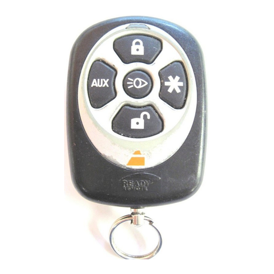
Page 75: Transmitter Button Configuration
CarFinder and Trunk Pop functions controls the Headlight activation, Panic & Silent mode functions controls the Alarm Arm and Locking functions controls the Alarm Disarm and Unlocking functions & activates the Vacation Mode feature & activates the Daily Start feature © 2007 Directed Electronics... -
Page 76: Remote Start Features
➤ The engine will start a few seconds after the parking lights flash. ➤ Once started, the lights will flash and it will run for the programmed period of time © 2007 Directed Electronics... - Page 77 The remote start can be shut down in several ways for convenience by the user or for safety by the shut down inputs. To shut down remote start: ➤ Press the transmitter button twice. ➤ Pulse the activation input wire twice ➤ Step on the brake. © 2007 Directed Electronics...
- Page 78 Press and release on the transmitter button twice. ■ Press and release the Momentary Switch 4 times quickly ■ Pulse the activation input wire twice ➤ The Horn/Siren will chirp once and the lights will begin © 2007 Directed Electronics...
- Page 79 Your vehicles’ engine will Remote Start in 24 hours. Note! The alarm and remote start functions will be fully operational while Daily Start is active. Important! When Daily Start is active ONLY park you car in a well ventilated areas. © 2007 Directed Electronics...
- Page 80 ➤ Temperature: the system will check the interior temper- ature and start if required every three hours ➤ Battery level: the system will start the engine immedi- ately when the battery level drops below 11.5 volts. © 2007 Directed Electronics...
- Page 81 3 seconds ➤ Activate Daily Start ➤ Activate the Ignition, Hood or Brake inputs at any time ➤ The parking lights will flash 5 times to confirm Vacation mode has been de-activated. (The Horn/siren will not chirp) © 2007 Directed Electronics...
-
Page 82: Alarm And Security Features
Note! If the door, brake or hood inputs are acti- vated during the 30 second countdown the timer will stop and reset, it will re-start once the input becomes inactive. Active sensor inputs will not stop the countdown. © 2007 Directed Electronics... - Page 83 Full Trigger output: this output consists of flashing the Parking lights and the Horn/Siren output for 30 seconds followed by a 5 second pause to monitor the alarm inputs. If an alarm input is still active the output will repeat. © 2007 Directed Electronics...
- Page 84 This system includes a Panic Mode operation that will alert other around you if you are threatened while in or near your vehicle. Due to state laws the Panic Mode is defeated when the ignition is on. © 2007 Directed Electronics...
- Page 85 1 hour. If a trigger occurs on that input while the bypass timer is active, the bypass timer will reset to 1 hour. You can Disarm and then Rearm the alarm to defeat the sensor bypass at any time. © 2007 Directed Electronics...
- Page 86 Press and hold the Momentary Switch. ➤ Turn the ignition On and Off in less than 5 seconds. ➤ Continue to hold the Momentary Switch. ➤ After 2 seconds the LED will turn off, Valet Mode is exited. © 2007 Directed Electronics...
-
Page 87: Convenience Features
Then using Silent Mode will temporarily turn on the Horn/Siren output. Headlight Control This feature allows you to toggle the headlight output on and off anytime the ignition is off. © 2007 Directed Electronics... - Page 88 Press and hold the button on the transmitter for 3 seconds. ➤ The alarm will disarm, unlock the doors and the auxiliary output will pulse. Note! The auxiliary output will stay active until the transmitter button is released. © 2007 Directed Electronics...
-
Page 89: Glossary Of Terms
RAP: Retained Accessory Power. After the vehicle is started and then shut down, the power to the radio remains on (retained) until a vehicle door is opened. Transmitter: A hand-held, remote control which operates the var- ious functions of your system. © 2007 Directed Electronics... -
Page 90: N N O O T T E E S
N N o o t t e e s s _____________________________________________________ _____________________________________________________ _____________________________________________________ _____________________________________________________ _____________________________________________________ _____________________________________________________ _____________________________________________________ _____________________________________________________ _____________________________________________________ _____________________________________________________ _____________________________________________________ _____________________________________________________ _____________________________________________________ _____________________________________________________ _____________________________________________________ _____________________________________________________ _____________________________________________________ _____________________________________________________ © 2007 Directed Electronics... - Page 91 © 2007 Directed Electronics...
- Page 92 The lights will flash 5 times and the Horn/Siren will chirp once to confirm. ■ To de-activate: Perform the same step to exit, the parking lights will flash 5 times, the Horn/siren will not pulse. © 2007 Directed Electronics...
- Page 93 © 2007 Directed Electronics...
- Page 94 © 2007 Directed Electronics...
- Page 95 The company behind this system is Directed Electronics Since its inception, Directed Electronics has had one purpose, to provide consumers with the finest vehicle security and car stereo products and accessories available. The recipient of nearly 100 patents and Innovations Awards in the field of advanced electronic technology, DIRECTED is ISO 9001 registered.