
Related Manuals for Directed Electronics READY REMOTE 24926


Summary of Contents for Directed Electronics READY REMOTE 24926
- Page 1 M M o o d d e e l l 2 2 4 4 9 9 2 2 6 6 ➤ O O w w n n e e r r ’ ’ s s / / I I n n s s t t a a l l l l a a t t i i o o n n G G u u i i d d e e...
-
Page 2: L L I I M M I I T T E E D D L L I I F F E E T T I I M M E E C C O O N N S S U U M M E E R R W W A A R R R R A A N N T T Y Y
Directed Electronics (hereinafter "Directed") promises to the original purchaser to repair or replace with a comparable reconditioned Directed DIY remote start unit if this Directed DIY remote start unit (hereinafter "Unit"), excluding without limitation, any... - Page 3 Make sure you have all of the following information from your dealer: A clear copy of the sales receipt, showing the following: Date of purchase ➤ Authorized dealer's company name and address ➤ ➤ Item number © 2006 Directed Electronics...
-
Page 4: Table Of Contents
: : ....................6 6 3 3 © 2006 Directed Electronics... - Page 5 © 2006 Directed Electronics...
-
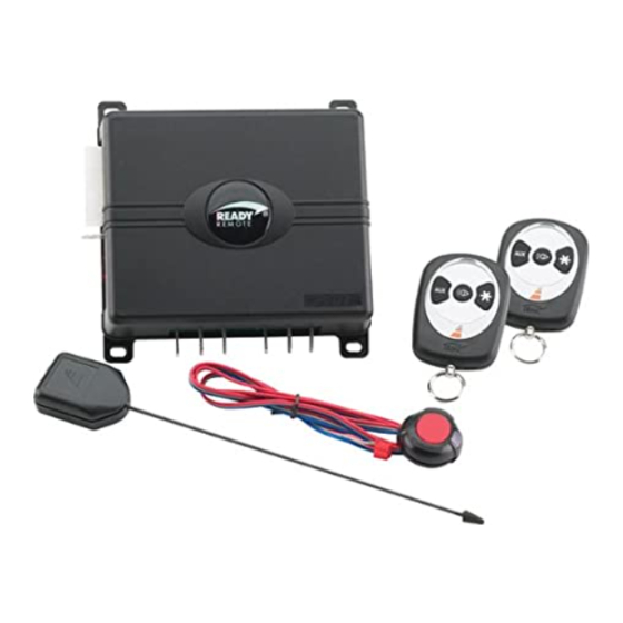
Page 6: What Is Included
Drill Bit (for hood pin switch) Screwdrivers (Phillips and Flathead) Wire Stripper Solder Iron Electrical Tape Pliers Crimping Tool note: The installation tools listed above may be optional and those required will vary depending on your vehicle. © 2006 Directed Electronics... -
Page 7: Important Information
The system requires no specific maintenance. Your transmitter is powered by a miniature 12-volt battery (type 23A) that will last approximately one year under normal use. When the battery begins to weaken, the operating range will be reduced. © 2006 Directed Electronics... -
Page 8: Fcc/Id Notice
4. THE USER MUST INSTALL A CARBON MONOXIDE DETECTOR IN OR ABOUT THE LIVING AREA ADJACENT © 2006 Directed Electronics... - Page 9 THESE CONDITIONS MAY RESULT IN PROPERTY DAMAGE OR PERSONAL INJURY. IMMEDIATELY CEASE THE USE OF THE UNIT AND REPAIR OR DISCONNECT THE INSTALLED REMOTE START MODULE. DIRECTED WILL NOT BE HELD RESPON- SIBLE OR PAY FOR INSTALLATION OR REINSTALLATION COSTS. © 2006 Directed Electronics...
-
Page 10: Wiring Quick Reference Guide
Wiring Quick Reference Guide © 2006 Directed Electronics... -
Page 11: H1 Harness - 6 Pin Connector
H1/6 Red/White This wire will start the vehicle when it sees two negative pulses. Only used when incorporating into existing alarm or for testing purposes. © 2006 Directed Electronics... -
Page 12: H2 Harness - 6 Pin Connector
Connect this wire to factory arm wire if equiped or to door trigger wire if your vehicle’s accessories stay on after remote start finishes cycle. H2/6 Yellow/Brown Headlight output. Connect this wire to headlight wire in car. If headlights are positive, a relay is required. © 2006 Directed Electronics... -
Page 13: Relay Heavy Gauge Wires
GREEN (+) Ign2 or Acc2 output PINK (+) 12 volt input BLUE (+) ignition 1 output WHITE (+) accessory output PINK (+) 12 volt input YELLOW (+) starter output BLACK (-) ground © 2006 Directed Electronics... -
Page 14: Installation Overview
Tampering may cause unintended deployment of airbags. ➤ This system is intended for automatic, fuel-injected vehicles only. Installation in any other vehicle is con- trary to its intended use. © 2006 Directed Electronics... -
Page 15: Step 1, Heavy Gauge Wire Connections
Using the appropriate hand tools, remove the lower dash panel taking care not to break any parts. If the panel does not come off easily, check for any additional screws you may have missed. © 2006 Directed Electronics... - Page 16 30 amp fuses are removed from the fuse holders on the two pink 12 VOLT wires. Failure to do so may cause fire or short- ing of sensitive electrical components. © 2006 Directed Electronics...
- Page 17 GREEN heavy gauge wire to it then wrap the connection with electrical tape. If your vehicle has only one ignition wire, secure the GREEN wire and dress it out of the way. © 2006 Directed Electronics...
- Page 18 2 nd IGNITION RELAY (NOT PROVIDED) TO 2 nd IGNITION GROUND TO 2 nd IGNITION +12 VDC CONSTANT (FUSED 20A) 3 rd IGNITION RELAY (NOT PROVIDED) GREEN (+) OUTPUT TO 2 nd IGNITION GROUND TO 3 rd IGNITION © 2006 Directed Electronics...
- Page 19 (NOT PROVIDED) WHITE (+) 30A OUTPUT TO ACCESSORY CIRCUIT GROUND TO 2 nd ACCESSORY If your vehicle requires more than one accessory then the GREEN ign2 wire can be programmed to function as an accessory output. © 2006 Directed Electronics...
- Page 20 TO 2 nd STARTER note! Always check the Web site information on your vehicle for warnings regarding the starter wire and check engine lights. Some vehicles will trip a check engine light if the starter wire is cut. © 2006 Directed Electronics...
- Page 21 Reconnect both ends of the starter wire while soldering the thick YELLOW (6) wire of the heavy guage wires to it and wrap the connection with electrical tape. © 2006 Directed Electronics...
-
Page 22: Step 2, H1, Main Harness Connections
Use the website to determine if your vehicle has a + trigger. If your vehicle has such a system call 1-800-477-1382 for live technical assistance as spe- cial wiring and an additional relay is required. © 2006 Directed Electronics... - Page 23 6-pin harness to it and wrap the connection with elec- trical tape. important! Remember this description is for a (+) parking light circuit. A (-) circuit will test differently. Also, if the web information requires using resistors for parking lights, contact Technical Support. © 2006 Directed Electronics...
- Page 24 (at the same time you might want to run Tachometer Input wire and Horn output wire from Optional Harness through the fire wall as you may need to connect them using the following steps). © 2006 Directed Electronics...
- Page 25 6-pin harness and wrap the connection with electrical tape. WARNING! This wire MUST be connected. Do not use the vehicle until you confirm the operation of the hood pin shutdown. Improper operation could result injury or death. © 2006 Directed Electronics...
-
Page 26: Step 3, H2 Harness
Second attempt: 20 seconds Third attempt: 50 seconds After the third start attempt, if the voltage increase is still not adequate to keep the engine running, the Tachometer input option should be used to monitor the engine. © 2006 Directed Electronics... - Page 27 Once the wire is run into the engine compartment, strip a small portion © 2006 Directed Electronics...
- Page 28 Continue to hold the switch for 2 - 3 seconds and release. Tach not learned: The LED will not turn on and will flash 3 times when the momentary switch is released. Check the connections and try again. © 2006 Directed Electronics...
- Page 29 The Brown wire is designed to turn off accessories that remain on after the ignition is turned off. It will pulse 10 seconds after the remote start status output ceases and will make the vehicle body control module think the door has opened, thus turning the acces- © 2006 Directed Electronics...
- Page 30 It is programmable in Feature Menu 1/10 for the type of ignition controlled activation. important! this is a low current output and that requires an external relay when connected to cir- cuits that draw more than 400mA in current. © 2006 Directed Electronics...
-
Page 31: Step 4, Mounting The Receiver/Antenna
To achieve the best possible range, DO NOT leave the antenna cable bundled under the dash. Always extend the cable full length dur- ing installation, regardless of the antenna mount- ing location. © 2006 Directed Electronics... - Page 32 © 2006 Directed Electronics...
-
Page 33: Step 5, Immobilizer Bypass Modules
To determine which bypass module your vehicle requires, use the website Interface Module Look-Up tool at www.readyremote.com. © 2006 Directed Electronics... -
Page 34: Step 6, Programming
For transmitter learn Step #1, you must press the “*” button on the transmitter, this will auto- matically program the transmitter buttons to the default function configuration. See the transmit- ter button auto learn chart for the assignment functions. © 2006 Directed Electronics... - Page 35 Momentary SW presses: if you press/release the momen- tary SW more times than transmitter Learning steps in the menu. The Horn output will pulse 5 times rapidly and the Led will turn off to indicate exiting feature programming. © 2006 Directed Electronics...
- Page 36 Daily Start Daily Start function Vacation Mode Vacation Start function Delete ALL TXs Removes ALL transmitters from memory Transmitter Button Auto-Learn Remote Start/Stop CarFinder Head Light control, Panic & Silent mode & Vacation Mode & Daily Start © 2006 Directed Electronics...
- Page 37 Press a button on the transmitter to change the feature option a. Option 1: Press the transmitter button assigned to the Remote Start function (usually the button) to set factory default Option 1. © 2006 Directed Electronics...
- Page 38 2 to feature location 8 press/release (do not hold) the Momentary switch 6 times, after 2 seconds the LED will flash 8 times to indicate the newly accessed feature location. © 2006 Directed Electronics...
-
Page 39: Feature Menu
0 degrees F -10 degrees F -20 degrees F Alarm Disarm 1 second 450 ms Horn Output Horn/Pulsing Siren/Constant Headlights Daytime Light your Start Chirp Reset All Options Press ANY TRANSMITTER button to reset all features © 2006 Directed Electronics... - Page 40 4. Ignition 2 Output: This controls the output type of the high current "Green" ignition 2 output wire. Ignition 2: Output will match the Blue Ignition 1 input/output wire operation during remote start. Accessory 2: Output will match the White Accessory 1 output wires operation. © 2006 Directed Electronics...
- Page 41 2. 450mS: The output will be 450mS in duration 9. Horn Output: Selects the type of output on the "Blue" Horn output wire when Panic Mode is activated but does not affect the remote start/programming chirp outputs © 2006 Directed Electronics...
- Page 42 Off: The Horn output WILL NOT pulse at the beginning of Remote Start 12. NA: A feature is Not Available for this Location 13. Reset All Options: Pressing a transmitter button when this Feature Location is accessed will "Reset All Options" to their default setting. © 2006 Directed Electronics...
-
Page 43: Remote Start Diagnostics
The unit is in the Valet Mode, Battery Voltage is below 11v, or the Brake or Hood inputs are active Quickstop The unit is in the Valet Mode, Battery Voltage is below 11v, or the Brake or Hood inputs are active © 2006 Directed Electronics... - Page 44 The Activation Input wire was used to activate the Remote starter Low temperature activated the Remote Starter in Vacation Mode Low battery voltage activated the Remote Starter in Vacation Mode No Diagnostics Daily Start activated the Remote Starter © 2006 Directed Electronics...
- Page 45 The Transmitter was used shut down remote start The 'Violet' Hood Input wire was activated Battery voltage level fell below required level The Tachometer Input level was x3 times learned value for >5sec The "Red/Wht" activation Input was used shut down remote start © 2006 Directed Electronics...
-
Page 46: Testing The System
1 press remote start operation) This completes the testing, if all functions do not work correctly check your wiring against the manual and verify all connections. If you still experience problems contact Directed Technical Support at 1-800-477-1382. © 2006 Directed Electronics... - Page 47 Make sure there is adequate clearance to the front and rear of the vehicle because it may move slightly. Make sure the hood is closed and there are no remote start shut-downs active. © 2006 Directed Electronics...
- Page 48 If the vehicle fails this test the remote start must be disabled until the proper Safety Interface has been installed that will keep the vehicle from starting while in gear. Failure to do so may result in property damage, injury or death. © 2006 Directed Electronics...
-
Page 49: Troubleshooting
The climate control system does not work. Either the wrong accessory wire is being energized or more than one ignition or accessory wire must be energized in order to operate the climate control system. ➜ The remote start will not activate. © 2006 Directed Electronics... - Page 50 ➜ The vehicle will start and run only for about 10 seconds. Is the remote start module programmed for voltage sense? If so, try programming the unit to tach mode. © 2006 Directed Electronics...
- Page 51 © 2006 Directed Electronics...
-
Page 52: O O W W N N E E R R ' ' S S G G U U I I D D E
M M o o d d e e l l 2 2 4 4 9 9 2 2 6 6 ➤ O O w w n n e e r r ’ ’ s s G G u u i i d d e e © 2006 Directed Electronics... - Page 53 ➤ Headlight output can operate as daytime running lights for safety or light your way securely into your home or office ➤ Silent Mode will defeat the chirps for remote start tem- porarily when needed © 2006 Directed Electronics...
-
Page 54: Transmitter Button Configuration
Remote Start/Stop functions controls the CarFinder feature controls the Headlight activation, Panic & Silent mode functions & activates the Vacation Mode feature & activates the Daily Start feature © 2006 Directed Electronics... -
Page 55: Remote Start Features
➤ The engine will start a few seconds after the parking lights flash. ➤ Once started, the lights will flash and it will run for the programmed period of time © 2006 Directed Electronics... - Page 56 The remote start can be shut down in several ways for convenience by the user or for safety by the shut down inputs. User remote start shut downs: ➤ The transmitter button is pressed twice. ➤ Pulse the activation input wire twice © 2006 Directed Electronics...
- Page 57 With the ignition On and the engine running, do one of the following: ■ Press and release on the transmitter button twice. ■ Press and release the Momentary Switch 4 times quickly ■ Pulse the activation input wire twice © 2006 Directed Electronics...
- Page 58 The parking lights will flash 4 times and the Horn/siren will chirp once to confirm Daily Start is activated. ➤ Your vehicles engine will Remote Start in 24 hours. important! When Daily Start is active ONLY park you car in a well ventilated areas. © 2006 Directed Electronics...
- Page 59 ➤ Temperature: the system will check the interior temper- ature and start if required every three hours ➤ Battery level: the system will start the engine immedi- ately when the battery level drops below 11.5 volts. © 2006 Directed Electronics...
- Page 60 Press and hold the button on the transmitter for 6 seconds ➤ The Horn/Siren output and light flash will activate for 45 seconds To de-active Panic Mode: ➤ Press and release the button on the transmitter © 2006 Directed Electronics...
- Page 61 Press and hold the Momentary Switch ➤ Turn the ignition On and Off in less than 5 seconds ➤ Continue to hold the Momentary Switch ➤ After 2 seconds the LED will turn off, Valet Mode is exited © 2006 Directed Electronics...
-
Page 62: Convenience Features
Then using Silent Mode will temporarily turn on the Horn/Siren output. Headlight Control This feature allows you to toggle the headlight output on and off anytime the ignition is off. To activate the Headlights: © 2006 Directed Electronics... - Page 63 ➤ The headlight output toggle on/off according to its present state note! The headlight output timer is 25 seconds and is controlled by the ignition input according to the programmed setting. © 2006 Directed Electronics...
-
Page 64: Glossary Of Terms
RAP: Retained Accessory Power. After the vehicle is started and then shut down, the power to the radio remains on (retained) until a vehicle door is opened. Transmitter: A hand-held, remote control which operates the var- ious functions of your system. © 2006 Directed Electronics... -
Page 65: N N O O T T E E S
N N o o t t e e s s _________________________________________________ _________________________________________________ _________________________________________________ _________________________________________________ _________________________________________________ _________________________________________________ _________________________________________________ _________________________________________________ _________________________________________________ _________________________________________________ _________________________________________________ _________________________________________________ _________________________________________________ _________________________________________________ _________________________________________________ _________________________________________________ _________________________________________________ _________________________________________________ _________________________________________________ _________________________________________________ _________________________________________________ © 2006 Directed Electronics... -
Page 66: Quick Reference Guide
The lights will flash 5 times and the Horn/Siren will chirp once to confirm. ■ To de-activate: Perform the same step to exit, the parking lights will flash 5 times, the Horn/siren will not pulse © 2006 Directed Electronics... - Page 67 The company behind this system is Directed Electronics Since its inception, Directed Electronics has had one purpose, to provide consumers with the finest vehicle security and car stereo products and accessories available. The recipient of nearly 100 patents and Innovations Awards in the field of advanced electronic technology, DIRECTED is ISO 9001 registered.