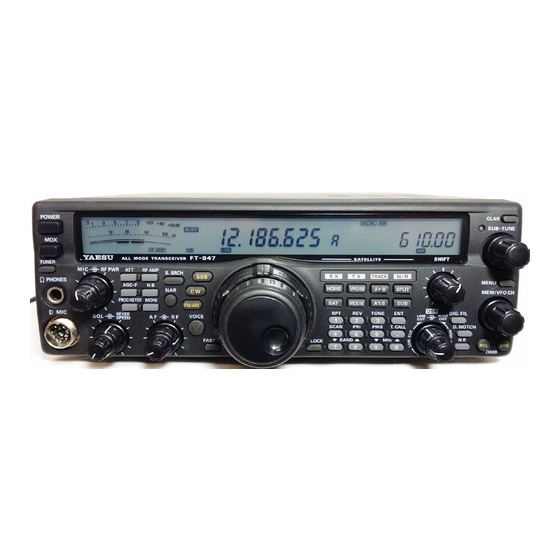
Yaesu FT-847 Operating Manual
Hf + v-uhf all mode transceiver
Hide thumbs
Also See for FT-847:
- Technical supplement (55 pages) ,
- Modification manual (21 pages) ,
- Technical supplement (54 pages)
Table of Contents
Advertisement
Quick Links
Download this manual
See also:
Technical Supplement
FT-847
OPERATING
MANUAL
YAESU MUSEN CO., LTD.
4-8-8 Nakameguro, Meguro-Ku, Tokyo 153-8644, Japan
YAESU U.S.A.
17210 Edwards Rd., Cerritos, CA 90703, U.S.A.
YAESU EUROPE B.V.
P.O. Box 75525 1118 ZN, Schiphol, The Netherlands
YAESU UK LTD.
Unit 12, Sun Valley Business Park, Winnall Close
Winchester, Hampshire, SO23 0LB, U.K.
YAESU GERMANY GmbH
Am Kronberger Hang 2, D-65824 Schwalbach, Germany
YAESU HK LTD.
11th Floor Tsim Sha Tsui Centre, 66 Mody Rd.,
Tsim Sha Tsui East, Kowloon, Hong Kong
Advertisement
Table of Contents

Related Manuals for Yaesu FT-847


Summary of Contents for Yaesu FT-847
- Page 1 FT-847 OPERATING MANUAL YAESU MUSEN CO., LTD. 4-8-8 Nakameguro, Meguro-Ku, Tokyo 153-8644, Japan YAESU U.S.A. 17210 Edwards Rd., Cerritos, CA 90703, U.S.A. YAESU EUROPE B.V. P.O. Box 75525 1118 ZN, Schiphol, The Netherlands YAESU UK LTD. Unit 12, Sun Valley Business Park, Winnall Close Winchester, Hampshire, SO23 0LB, U.K.
-
Page 2: Table Of Contents
Table of Contents Transmitting............43 General description ..........1 SSB Transmission ..........44 Specifications ............2 Basic Operation ..........44 Accessories & Options ..........4 RF Speech Processor Operation ......45 Plug Pinout ............... 5 Voice Monitor ........... 45 Installation ..............6 SSB TX Frequency Response ...... -
Page 3: General Description
HF Amateur bands, plus VHF/UHF coverage of the 50, 144, and 430 MHz bands. The FT-847 Earth Station provides 100 Watts of power output on 160 through 6 meters, and 50 Watts output on 144 MHz and 430 MHz. General-coverage HF receive capability is provided, along with VHF/UHF reception at 37~76 MHz, 108~174 MHz, and 420~512 MHz. -
Page 4: Specifications
Opp. Sideband Suppression: At least 40 dB 3rd-Order IMD: At least 31 dB down (14 MHz, 100W PEP output) SSB Frequency Response: 400 Hz - 2600 Hz ( 6 dB) Microphone Impedance: 200 - 10k (Supplied microphone: 600 ) FT-847 O PERATING ANUAL... - Page 5 Audio Output: At least 1.5W into 8 @ 10% THD Audio output impedance: 4 - 16 Specifications are subject to change, in the interest of improvement, without notice or obligation. Specifications are guaranteed only within Amateur bands. FT-847 O PERATING ANUAL...
-
Page 6: Accessories & Options
FP-1023 AC Power Supply, Switching Regulator Type (23A) (U.S.A. only) CT-39 Packet Cable CT-61 STBY Cable RCA Connector (P/N P0090544) 5-pin Mini DIN Plug (P/N P0090976) 3-pin Phone Plug (P/N P0090008) 2-pin Miniature Plug (P/N P0090034) FT-847 O PERATING ANUAL... -
Page 7: Plug Pinout
Plug Pinout FT-847 O PERATING ANUAL... -
Page 8: Installation
Installation OWER ONNECTIONS The DC power connector for the FT-847 must only be Note that other manufacturers may use the same type connected to a DC source providing 13.8 Volts DC of DC power connections as does your FT-847 trans- (±10%), and capable of at least 22 Amperes of cur-... - Page 9 (heat shrink tubing plus black electri- cal tape work well). r Be sure that the POWER switch on the FT-847 is OFF when connecting the DC cable’s connector to the rear panel 13.8VDC jack.
-
Page 10: Grounding
See the drawings below for examples of proper and improper ground connections. Inspect the ground system inside the station as well as outside on a regular basis so as to ensure maxi- mum performance and safety. FT-847 O PERATING ANUAL... -
Page 11: Mobile Station Grounding
RF grounding can nullify such filtering. Bonding the rear panel Ground lug of the FT-847 transceiver to the vehicle or vessel’s ground system should clear up any such difficulties. -
Page 12: Antenna Considerations
50 re- When installing a “balanced” antenna such as a Yagi sistive impedance at the desired operating frequency. or dipole, remember that the FT-847 is designed for While minor excursions from the 50 specification use with an (unbalanced) coaxial feedline. -
Page 13: Mobile Antenna Installations
Do not allow discon- losses increase so rapidly in the presence of nected cables to touch the case of your FT-847 trans- SWR that we recommend that all antenna ceiver or accessories, as lightning can easily jump from... -
Page 14: Rf Field Exposure
Although there is negligible radio frequency (RF) leak- ment, and decoupling ferrite toroidal chokes may be age from the FT-847 transceiver itself, its antenna sys- required on interconnecting patch/data cables. As a tem should be located as far away from humans and... -
Page 15: Heat And Ventilation
FT-847. ceiver. Do not install the transceiver on top of another heat-... -
Page 16: Accessory Interfacing
Installation CCESSORY NTERFACING The FT-847 may be connected to a wide variety of Important Note! accessories in your amateur station. Wherever possible Do not exceed the maximum voltage or current (e.g. PTT, ALC, KEY, SPKR, PKT, DATA, ratings for the STBY jack. This jack is not com-... -
Page 17: Vhf/Uhf Preamplifiers
FT-847 is used, and no DC power is deliv- tennas are isolated from the FT-847 by the ered to the rear panel antenna jack(s). -
Page 18: Afsk Tnc Connections
Some digital modes, such as RTTY (Radio (for HF RTTY and Packet, etc.) TeleType), require continuous key-down trans- The FT-847 is easy to connect to most all Terminal mission. While the internal fan is designed to Node Controllers (TNCs) or other digital modem units... -
Page 19: Fm Packet Tnc Interfacing
TNC “Radio 1” port to the 1200 bps lines on the are slightly lower than the level of your speech. If you FT-847, and the “Radio 2” port to the 9600 bps lines. have the optional MH-36 DTMF Microphone, set your TNC’s tone output to be about the same level as... -
Page 20: Cw Accessory Interfacing
20 mV with an impedance of 10 k . “negative” or “grid block” keying. The “key-up” volt- age of the FT-847 is +5V, and the “key-down” current is only about 2 mA. For CW automated keying using a personal computer,... - Page 21 Installation FT-847 O PERATING ANUAL...
-
Page 22: Front Panel Controls & Switches
This ¼” 3-pin (“stereo”) jack is used for connection to your headphones. When a plug is inserted into this jack, the internal (or external) speaker will be cut off. This jack’s impedance is optimized for use with 16 to 32 headphone types. FT-847 O PERATING ANUAL... - Page 23 In the CW mode, pressing this switch activates the built-in Electronic Keyer circuit. When ac- tivated, the “K E Y E R ” icon will appear on the display panel. FT-847 O PERATING ANUAL...
- Page 24 FM operation on 29 MHz. Press this switch to select which provides announcement of the operating fre- the Narrow mode; the “NAR” icon will appear on the quency (with resolution to the displayed 100 Hz digit) display panel. for operators with vision impairments. FT-847 O PERATING ANUAL...
- Page 25 In this mode, the MAIN VFO Tuning Dial is used to control the downlink (receive) frequency during satellite operation. [TX] (VFO/M) In this mode, the MAIN VFO Tuning Dial is used to control the uplink (transmit) frequency during satellite operation. FT-847 O PERATING ANUAL...
- Page 26 VFOs are used for crossband satellite operation. The “ ” icon will appear on the display panel during Pressing this switch momentarily allows direct key- satellite operation. board frequency entry and/or mode change to be per- formed on the Sub VFO register. FT-847 O PERATING ANUAL...
- Page 27 This switch is used for one-touch recall of the Quick the available offset range is ±9.99 kHz. Memory Bank memory. (43) QMB STO Switch This switch is used for storing a Main VFO frequency into the QMB memory register. FT-847 O PERATING ANUAL...
-
Page 28: Display Indicators And Icons
: RF Speech Processor is engaged. : CW Electronic Keyer is engaged. is engaged. ONITOR : Receiver Input A is engaged. TTENUATOR : Receive Preamplifier is in line. : Fast AGC is engaged. : IF Noise Blanker is engaged. FT-847 O PERATING ANUAL... - Page 29 : Main Band is used for Transmit, Sub Band is used for Receive. : CW : Inverted “Reverse” Frequency Tracking is engaged. : AM : Linear “Normal” Frequency Tracking is engaged. : FM : Narrow Filter is engaged. FT-847 O PERATING ANUAL...
-
Page 30: Rear Panel Connectors
Use a “null modem” (not “straight”) RS-232C serial data cable; no “level converter” or other hardware interface should be required. FT-847 O PERATING ANUAL... - Page 31 Note: This jack is designed to be used for external PTT input only. Do not attempt to use the PTT jack for switching of amplifiers or other exter- nal devices (use the STBY jack for controlling such devices). FT-847 O PERATING ANUAL...
-
Page 32: Operation
SQL & KEYER SPEED: Fully counter-clockwise (minimum) LOW CUT: Fully counter-clockwise HIGH CUT: Fully clockwise SHIFT: 12 o’clock Connect your microphone and/or CW key or paddle, connect the DC cable to the rear panel 13.8VDC jack. FT-847 O PERATING ANUAL... -
Page 33: Operation Quick Start
‡ To set a frequency directly from the keyboard, press [ENT], followed by the frequency (enter the deci- mal point after the “MHz” portion of the frequency), then push [ENT] to finish your entry. FT-847 O PERATING ANUAL... -
Page 34: Receiver Operation
The VFO (Variable Frequency Oscillator) system in on which you are currently receiving will be the only the FT-847 is the primary method of frequency navi- band on which the change in frequency steps is ex- gation. Separate VFOs are provided for the Main (left) ecuted. -
Page 35: Shuttle Jog Tm Ring
FrE: This selection locks out the knobs and switches in the shaded areas of the il- lustration below. „ Press the [MENU] key again when you are satisfied with your selection. This causes you to exit from the Menu mode. FT-847 O PERATING ANUAL... -
Page 36: Mem/Vfo Ch Knob
(the “straight” cable does not include scan- grammed steps (the “FAST” icon will disapper ning lines, as it is intended only to pass micro- from the LCD). phone and PTT signals from the microphone shaft). FT-847 O PERATING ANUAL... -
Page 37: Qbandp And Qmhzp Keys
The procedure for entering a frequency is simple: l Press the [ENT] key to begin the entry process. new band, the FT-847 will move you to the last fre- l Enter the “MHz” portion of the frequency on quency and mode on which you were operating on that band. -
Page 38: Receiver Features
(press the [AGC-F] key once more to turn off the band. The available choices are: “AGC-F” icon). l INT: The preamplifier internal to the FT-847 will be selected. l EXT: The internal preamplifier will be bypassed, and +12V DC will instead be sent up the co- axial line for powering an external preamp. -
Page 39: Rf Gain Control
“splatter” on a nearby signal (if that station is very strong). Try switching off the N if you observe these OISE LANKER conditions. FT-847 O PERATING ANUAL... -
Page 40: Dsp Noise Reduction
OICE YNTHESIZER The level of noise reduction applied by the DSP The FT-847 includes the capability for the use may be adjusted via Menu #11. The default set- ting, on an arbitrary scale of 0 (minimum noise of the (optional) FVS-1A V... -
Page 41: Meterring
ECEIVER EATURES Dealing with Interference ETERING The FT-847 includes dual meter functions, useful in The FT-847 includes a wealth of features designed to many operating situations. facilitate single-signal reception during conditions of heavy interference. These features are described be- ATELLITE low. -
Page 42: If Shift
The SHIFT control’s function is dedicated to the receive mode, and does not affect your trans- mitted signal characteristics; such adjustment of the transmitted signal is, however, provided via Menu items #92 and 93, as described on page 90. FT-847 O PERATING ANUAL... -
Page 43: Notch Filter (Dsp)
OTCH [D. NOTCH] switch; the “NOTCH ” icon The FT-847 can be quickly configured, so as to avoid will appear on the display. To turn this fil- these problems, to utilize either “USB” or “LSB” car- ter off, press the [D. NOTCH] switch again. - Page 44 OPERATION FT-847 O PERATING ANUAL...
-
Page 45: Transmitting
OWER UTPUT EVEL ONITORING tion, we shall explore the FT-847’s capabilities in the During transmission, you have the option of monitor- transmit mode. ing RF power output (“PO” on the Meter) or relative ALC voltage (“ALC” on the Meter). The default set-... -
Page 46: Ssb Transmission
For hands-free operation when using a desk micro- mode. You may wish to reset the TX Multimeter phone, such as Yaesu’s model MD-100 back to “PO” via Menu #24 at this time (see previ- footswitch (which shorts two contacts together) ous discussion). -
Page 47: Rf Speech Processor Operation
DJUSTMENT s i g n i f i c a n t i n c r e a s e i n y o u r Although your FT-847 is carefully aligned at the fac- transmitter’s average power output. tory for the best average frequency response for most... -
Page 48: Cw Transmittion
OPERATION CW T RANSMISSION The FT-847’s versatile design is engineered to provide the operating flexibility required for contest, DX, or weak- signal VHF/UHF operation. TRAIGHT XTERNAL EYING EVICE PERATION This section describes the operating procedure using a manual “straight key.” This section also pertains to opera- tion using the output from an external electronic keyer, or from a CW keying interface utilized with a personal computer (using contest software, etc.). - Page 49 10 ~ 300 ms. l Press the [MENU] key to exit the Menu mode. Although the FT-847 was not designed for “full QSK” operation, the minimum setting of Menu #9 (10 ms) will be very close to full break-in perfor- mance.
-
Page 50: Electronic Keyer Operation
OPERATION CW T RANSMISSION LECTRONIC EYER PERATION The FT-847’s built-in electronic keyer is flexible, yet easy to use. • Insert your key’s ¼” three-conductor (“stereo”) plug CW S EATURE into the KEY jack on the rear panel of the trans- During CW operation, it is useful to be able to zero in ceiver. - Page 51 OPERATION CW T RANSMISSION FT-847 O PERATING ANUAL...
-
Page 52: Fm Transmission
HANNELIZED REQUENCY AVIGATION and the FT-847 provides a wealth of features for AM You may find that the MAIN VFO Tuning Dial is some- simplex and repeater operation. Several of these fea- what inconvenient for FM operation, since most all tures may be customized for each band via the Menu stations operating in the FM mode use a “channelized”... -
Page 53: Simplex (Non-Repeater) Operation
Press the [MENU] key to exit the Menu mode. l Close the microphone’s PTT switch, and speak into the microphone to check the mic gain level. If further adjustment is required, repeat the above procedure. FT-847 O PERATING ANUAL... -
Page 54: Repeater Operation
The default repeater shift may be changed indepen- dently on each of the four FT-847 bands on which re- Note: With the ARS turned On, the repeater shift icon peater operation is authorized. The setting of the re-... -
Page 55: Ctcss Operation
Tone Frequency. A total of 39 your conversation. internationally-recognized CTCSS tones are provided on the FT-847. The CTCSS Tone Frequency is set using Menu #12. For example, to set a CTCSS Tone Frequency of 103.5 Hz, use the following procedure: l Press the [MENU] button to activate the Menu mode of operation. -
Page 56: Dcs (Digital Coded Squelch) Operation
152 155 156 162 165 172 174 205 212 223 225 226 243 244 245 246 251 252 255 261 263 265 266 271 274 306 Because your FT-847’s receiver will be silent 311 315 325 331 332 343 346 351 356 364 365 371 411... -
Page 57: Cross-Band Repeater Operation
ROSS BAND EPEATER PERATION The FT-847 can be set up to operate as a one-way Here is the procedure for setting up cross-band repeater “range extender,” using the Menu system. This fea- operation: ture is useful for emergency portable work in a remote •... -
Page 58: Fm Packet Operation
OPERATION FM P ACKET PERATION The FT-847 may easily be configured for 1200 or 9600 bps packet operation. • „ Refer to page 17, and connect your TNC (Termi- Set the transceiver to the desired operating fre- nal Node Controller) to the rear panel’s PKT jack, quency. -
Page 59: Afsk Rtty/Data Operation
Using the keyboard of the computer connected to your TNC, you may now issue the “Connect” com- mand, and begin operation. When you transmit via the DATA IN/OUT jack, the “DATA” icon will ap- pear on the display. FT-847 O PERATING ANUAL... -
Page 60: Am Transmission
OPERATION AM T RANSMISSION The FT-847 includes provision for AM transmission using an early-stage modulator. • Connect your microphone to the front panel MIC jack. Preset the MIC (G ) control fully counter- clockwise. ‚ Press the FM/AM mode key, as necessary, to select the “AM”... -
Page 61: Operation On Alaska Emergency Frequency
The full used when the immediate safety of human life and/ specifications of the FT-847 are not necessarily or property are threatened, and is never to be used guaranteed on this frequency, but power output and for routine communications. -
Page 62: Antenna Tuner (Fc-20) Operation
The optional FC-20 (external) Automatic Antenna Tuner may be helpful, in some installations, in maintaining a satisfactory impedance match between your coaxial feedline and the FT-847’s final amplifier stage. The FC-20 operates on the 160 through 6 meter bands, and is capable of achieving an impedance match in the presence of up to 3:1 SWR (impedance range: 16.5 ~ 150 ) on HF, and 2:1 SWR on 50 MHz (25 ~ 100 ). - Page 63 NTENNA UNER EMORY YSTEM The FC-20, working in concert with the FT-847, can frequency a few kHz, then press the [TUNER] key store impedance matching data in its micro-computer again for ½ second, as slight changes in the reac- memory, so as to provide instant adjustment as you tance may allow a match to be obtained.
-
Page 64: Active-Tuning Antenna System (Atas-100) Operation
(to lower the antenna). tenna) or the [MH the reading on the meter. While you hold in one of these keys, the FT-847 will ƒ When tuning is successfully completed, the FT-847 generate a carrier, and you may watch the top scale of will return to the receive mode. - Page 65 If, however, you stop manual tuning at a non-opti- rier, although the mode indication will not change mum setting (SWR >2:1), the FT-847 will not per- to “CW” (if you are operating on another mode) mit further automatic tuning. To refresh the setting...
-
Page 66: Split Trequency Operation (Non-Satellite)
PERATION ATELLITE The FT-847 provides convenient split-frequency operation, using the Main and Sub VFOs, for DX working and other operating situations requiring unique split frequency pairs. For repeater operation using the default shifts provided, see page 52. Split operation per this section is not a “full-duplex” configuration as needed for satellite operation;... - Page 67 OPERATION FT-847 O PERATING ANUAL...
-
Page 68: Satellite Operation
OPERATION ATELLITE PERATION The FT-847 is an outstanding performer on amateur satellites, providing “turn-key” operation on Voice/CW “ana- log” satellites, and easy interface for digital mode operation. The chief features of the FT-847 for satellite operation include: l Full duplex crossband capability, pioneered on the Yaesu FT-726R;... - Page 69 Sub VFO). If “TCK-REV ” does not appear, press Note: Operation on satellite Mode “K” is not possible the [N/R] key once to change the Tracking mode. with the FT-847, as both the uplink (21 MHz) ‡ Press and hold in the [MCK/W] key momentarily;...
-
Page 70: Satellite "Memory" Registers
During transmission, the lower meter scale may be set, isters which function as independent VFO pairs; these via Menu #34, to indicate one of three possible condi- allow the FT-847 to be configured for a number of tions: different satellites, each with its own frequency and A. -
Page 71: Satellite Memory Labeling
(“SAT TAG”). The wide variety of amateur satellites provides many l Press the[MCK/W] key. opportunities to utilize the flexibility of the FT-847. l Rotate the MEM/VFO CH knob to select the For example, some digital satellites may require an Satellite Memory to which an alpha-numeric uplink signal to be sent on FM, while downlinking on Tag is to be appended. -
Page 72: Memory Operation
MEMORY OPERATION The FT-847’s Memory System provides a wide variety of facilities which enhance operating efficiency and conve- nience. The Memory System stores frequency, operating mode, bandwidth, repeater offset and tone data, and information, to minimize the need to reset controls each time a memory channel is recalled. The features LARIFIER of the Memory System are described on the pages to follow. -
Page 73: Main Memory System
MEMORY OPERATION EMORY YSTEM The Main Memory System of the FT-847 consists of memory channels 1 through 78, which provide the user with a huge bank of memories for every operating need. ( “S ” ) M ORMAL IMPLEX EMORY TORAGE Use this procedure for storage of most frequencies, when not operating either in the “Split”... -
Page 74: Split-Frequency Memory Storage
PTT switch, again same channel as a previously-stored Receive press the [MCK/W] key for ½ second. The double frequency. “beep” will confirm that independent Transmit fre- quency data is now stored. You may now release the [PTT] switch. FT-847 O PERATING ANUAL... -
Page 75: Memory Cannel Recall
Sub VFO Display field is not the “Trans- memory channel for storing the new frequency mit” frequency during “Split” memory data. operation. When operating on a “Split” frequency memory (see previous page), the “+, –” indication will appear on the display. FT-847 O PERATING ANUAL... -
Page 76: Home" Channel Memory
Memory mode). The “H ” indication will appear in the memory channel number field to the right of the main frequency display area. Press the [HOME] key once more to return to the previous frequency (either a VFO frequency or a memory channel). FT-847 O PERATING ANUAL... -
Page 77: Erasing Individual Memories
That is, if you are presently using a 144 MHz memory channel, pressing the [HOME] key to switch to VFO operation on, for example, 14 MHz, pressing the [HOME] key will cause the “HF Band” H channel to be recalled. FT-847 O PERATING ANUAL... -
Page 78: Smart Search
… The S ™ process will now cause the tarily. MART EARCH FT-847 to scan upward in frequency on the current Note: S ™ memories for frequencies MART EARCH band, loading channels on which it encounters a above the original operating frequency are num- signal strong enough to open the squelch. -
Page 79: Priority Channel Operation
‚ Press the keypad’s [5(PRI)] key momentarily to initiate the Priority mode. The FT-847 will con- tinue to operate normally on the current frequency, but every five seconds will switch briefly to Memory Channel #1, looking for activity. If no ac- tivity is found, operation will resume on the cur- rent frequency. -
Page 80: Scanning Operation
Scanning Operation The FT-847’s Scanning capability allows you to monitor a large number of Memory Channels, or to sweep a band (or band segment), looking for activity. For scanning just a band segment, see page 80 for operating instructions for the “P ”... -
Page 81: Memory Channel "Skip" Feature
The “S K IP ” icon will appear above the channel number on the display. „ ‚ ƒ Repeat steps if you want to skip other channels. … Press the [MCK/W] key once more to exit to nor- mal operation. FT-847 O PERATING ANUAL... -
Page 82: Programmable Memory Scan
“hold” time set via Menu #26 For the purposes of PMS scanning, the oper- (FM/AM modes, see page 86). ating mode and synthesizer steps programmed into the frequency associated with the “L ” memory slot will be utilized. FT-847 O PERATING ANUAL... -
Page 83: Weatherfax Monitoring
WeatherFax Monitoring Monitoring of HF WeatherFax broadcasts is easily accomplished using the FT-847. • Before proceeding, be certain that the WeatherFax demodulator is properly connected to the rear panel DATA IN/OUT jack (only the “RX” ring and ground contacts are required; the tip connector is not used). -
Page 84: Menu System
Menu System The FT-847’s Menu system allows customization of many aspects of transceiver performance by the owner. The parameters adjusted via the Menu system are performance characteristics which do not require adjustment in “real time” by the operators, but rather are “set-and-forget” parameters which optimize the transceiver’s setup configu- ration for the way you like to operate. -
Page 85: Menu System Selection Chart
0 Hz Rx Carrier Injection Point (LSB) 100 ~ +150 Hz 0 Hz Cloning Data Transfer Baud Rate 9600/57600 bps 9600 bps Clone Mode "SEND" Clone Mode "RECEIVE" Note: Default setting may vary in different countries. FT-847 O PERATING ANUAL... -
Page 86: Menu Selection Details
VHF/UHF: Depends on trans- A longer delay may be preferable if you pause fre- ceiver version (U.S.A., European, etc.) quently while sending. This setting may be performed individually on HF, 50 MHz, 144 MHz, and 430 MHz. FT-847 O PERATING ANUAL... - Page 87 412 413 423 431 432 445 446 452 454 455 462 464 465 466 503 506 516 523 526 532 546 565 606 612 624 627 631 632 654 662 664 703 712 723 731 732 734 743 754 FT-847 O PERATING ANUAL...
- Page 88 ” message when you transmit, as RROR ALC plus any external ALC voltage which may be the resulting transmit frequency would be outside the fed to the FT-847 from an external linear amplifier. amateur band. 25 [FM P-SET] 20 [MONI-VOL]...
- Page 89 Default Setting: I If you desire to use both the internal preamplifier and a tower-mounted preamplifier, select the “I ” setting, then provide power to your tower-mounted preampli- fier via a separate power cable. FT-847 O PERATING ANUAL...
-
Page 90: Satellite Memory Alpha-Numeric Tag Programming
Default Setting: 4800 bps 38 [MEM CLR] Function: Clear all memories. While in this Menu selection, pressing the [MCK/W] key causes all Memories to be cleared, but any cus- tom Menu settings you have programmed will not be affected. FT-847 O PERATING ANUAL... - Page 91 Tag contents. In the above example, the Tag shows “OSCAR10B” for “Oscar 10, Mode B.” † Press the [MCK-W] key momentarily when entry of the Alpha Tag is completed. ‡ Press the [MENU] key to exit the Menu mode. FT-847 O PERATING ANUAL...
- Page 92 (i.e. 100 ~ 150 Hz) When this Menu selection is active, pressing the Default Setting: 0 Hz [MCK/W] key places the FT-847 in the “Clone Data Analogous to “IF Shift” on receive, the TX Carrier Receive” mode, ready to accept the transfer of clon- Point adjustment allows you to shift the IF passband ing data from another FT-847.
-
Page 93: Cat System Programming
Important Notice! of pins for connection to your system. Note that this cable is different from the type utilized on earlier Yaesu It is not possible to engage the System System transceivers. - Page 94 •¦ •¦ P1=13: Read SAT RX VFO Frequency & Mode Status P1=23: Read SAT TX VFO Frequency & Mode Status (Note 3) Note 1: Receiver Status Note 3: Frequency & Mode Status Note 2: Transmit Status FT-847 O PERATING ANUAL...
- Page 95 OMMAND cations: OMMAND TRUCTURE There are 25 instruction opcodes for the FT-847, listed in the chart on previous page. Many of these opcodes are On/Off toggle commands for the same action (e.g. “PTT On” and “PTT Off”).Most of these commands Send these five bytes to the transceiver, in the require some parameter or parameters to be set.
-
Page 96: Transceiver-To-Transceiver Cloning
On the transceiver which will receive the Cloning data, activate Menu #97 (“RCV CLN ”) by pressing and memory information from one FT-847 to another. The data format is only compatible with other FT-847 the [MCK/W] key momentarily after selecting transceivers. -
Page 97: Installation Of Optional Accessories
Compared to the stock Ceramic Filter, the Collins® Mechanical Filter provides deeper suppression of an- noying interference to the side of your current frequency, although the bandwidths of the two filters (at -6 dB) are approximately the same. FT-847 O PERATING ANUAL... -
Page 98: Optional Voice Synthsizer Unit (Fvs-1A)
FVS-1A IC. … Fold the front panel back into place, and replace the covers and carrying handle. Figure 3 Figure 4 Figure 5 FT-847 O PERATING ANUAL... -
Page 99: Cpu Resetting & Memory Backup
ESET ROCEDURES DC power is turned off, via a lithium backup battery If you wish to reset the FT-847’s microprocessor to its with an estimated lifetime of approximately five years. original factory default settings (all memories and cus- No data essential to the fundamental operation of the tomized Menu settings will be lost), use the follow- radio is stored in “volatile”... -
Page 100: In Case Of Trouble
UDIO ¦ Check to see if the DSP LOW CUT or HIGH CUT Keyer” device, ensure that both “TX Audio” and “PTT” cables are connected (because the FT-847 controls are improperly positioned. Switch DSP Off does not have “VOX” circuitry). - Page 101 MEM/VFO ¦ Ensure that any contest or logging software used CH knob). supports the FT-847, and that the “Radio Control” ¦ If no repeater shift takes place, check settings of protocol is enabled on the software.
-
Page 102: Appendix
150 watts of power. solid state amplifiers in the 100W ~ 300W range. More ‚ Set the FT-847 to the CW mode, and activate the power and (especially) more antennas will improve DSP Bandpass Filter (and NR filter, if you like). - Page 103 Try to match your sending speed to that of commonly-available hardware may be used in conjunc- tion with your FT-847 to let you experience “The Ul- the other station, and be sure your station’s clock timate DX.”...
-
Page 104: High-Speed Cw Meteor Scatter Operation
Remember that the AFSK output level from the DATA of the FT-847 is such that you can easily set up the IN/OUT jack is fixed, so you may monitor the receiv-... - Page 105 HSCW is much higher than with slower-speed CW or westernmost station to transmit during the “even” min- SSB, and reducing the power output from the FT-847 utes of the hour, (e.g. 1900~1901, 1902~1903, etc.), to about 50% of its rated maximum is therefore rec- while the easterly station transmits on the “odd”...
- Page 106 BBB: Both callsigns are needed MMM: My callsign is needed (your call was received OK) YYY: Your callsign is needed (my call was received OK) SSS: Your “Report” is needed UUU: Your keying is not readable (technical problem) FT-847 O PERATING ANUAL...
- Page 107 This device complies with Part 15 of the FCC rules. Operation is subject to the condition that this device does not cause harmful interference.
- Page 108 ..leading the way. Copyright 1998 Yaesu Musen Co., Ltd. All rights reserved. No portion of this manual may be reproduced without the permission of Yaesu Musen Co., Ltd. 9911I-GK...