ZyXEL Communications NWA-1100 Manual
802.11b/g/n poe access point
Hide thumbs
Also See for NWA-1100:
- User manual (225 pages) ,
- Quick start manual (144 pages) ,
- Brochure (2 pages)
Table of Contents
Troubleshooting

Related Manuals for ZyXEL Communications NWA-1100


Summary of Contents for ZyXEL Communications NWA-1100
- Page 1 NWA1100-N 802.11b/g/n PoE Access Point Default Login Details IP Address http://192.168.1.2 Password 1234 Firmware Version 1.00 Edition 1, 3/2011 www.zyxel.com www.zyxel.com Copyright © 2011 ZyXEL Communications Corporation...
-
Page 3: About This User's Guide
This manual is intended for people who want to configure the NWA using the web configurator. Tips for Reading User’s Guides On-Screen When reading a ZyXEL User’s Guide On-Screen, keep the following in mind: • If you don’t already have the latest version of Adobe Reader, you can download it from http:// www.adobe.com. - Page 4 Customer Support Should problems arise that cannot be solved by the methods listed above, you should contact your vendor. If you cannot contact your vendor, then contact a ZyXEL office for the region in which you bought the device. See http://www.zyxel.com/web/contact_us.php for contact information. Please have the following information ready when you contact an office.
-
Page 5: Document Conventions
Syntax Conventions • The NWA1100-N may be referred to as the “NWA”, the “device”, or the “ZyXEL Device” in this User’s Guide. • Product labels, screen names, field labels and field choices are all in bold font. - Page 6 Document Conventions Table 1 Common Icons Computer Notebook Server Printer Firewall Switch Router Internet Cloud NWA1100-N User’s Guide...
-
Page 7: Safety Warnings
Safety Warnings Safety Warnings • Do NOT use this product near water, for example, in a wet basement or near a swimming pool. • Do NOT expose your device to dampness, dust or corrosive liquids. • Do NOT store things on the device. •... - Page 8 Safety Warnings NWA1100-N User’s Guide...
-
Page 9: Table Of Contents
Contents Overview Contents Overview User’s Guide ........................... 17 Introducing the NWA ........................19 Introducing the Web Configurator ....................29 Status Screens .......................... 33 Tutorial ............................37 Technical Reference ......................53 System Screens ........................55 Wireless Settings Screen ......................60 SSID Screen ..........................79 Wireless Security Screen ...................... - Page 10 Contents Overview NWA1100-N User’s Guide...
-
Page 11: Table Of Contents
Table of Contents Table of Contents About This User's Guide ......................3 Document Conventions......................5 Safety Warnings........................7 Contents Overview ........................9 Table of Contents........................11 Part I: User’s Guide................17 Chapter 1 Introducing the NWA ......................19 1.1 Introducing the NWA ......................19 1.2 Applications for the NWA ..................... - Page 12 Table of Contents 3.1 The Status Screen ....................... 33 3.1.1 System Statistics Screen .................... 35 Chapter 4 Tutorial ............................. 37 4.1 How to Configure the Wireless LAN ..................37 4.1.1 Choosing the Wireless Mode ..................37 4.1.2 Wireless LAN Configuration Overview ............... 37 4.1.3 Further Reading ......................
- Page 13 Table of Contents 6.4 Wireless Settings Screen ....................62 6.4.1 Access Point Mode ....................63 6.4.2 Bridge / Repeater Mode ..................... 65 6.4.3 AP + Bridge Mode ...................... 69 6.4.4 Wireless Client Mode ....................70 6.4.5 MBSSID Mode ......................73 6.5 Technical Reference ......................
- Page 14 Table of Contents 8.4.5.1 Access Point ................... 95 8.4.5.2 Wireless Client ................96 8.4.6 Security: WPA-PSK, WPA2-PSK, WPA2-PSK-MIX ............ 97 8.5 Technical Reference ......................98 Chapter 9 RADIUS Screen ........................99 9.1 Overview ..........................99 9.2 What You Can Do in this Chapter ..................99 9.3 What You Need to Know ......................
- Page 15 Table of Contents 12.8.1 MIB ..........................116 12.8.2 Supported MIBs ......................116 12.8.3 SNMP Traps ......................117 Chapter 13 Certificate Screen ......................... 119 13.1 Overview ...........................119 13.2 What You Can Do in this Chapter ..................119 13.3 What You Need To Know ....................119 13.4 Certificate Screen ......................120 13.5 Technical Reference ......................
- Page 16 Table of Contents Appendix A Product Specifications ..................141 Table 51 Power over Ethernet (PoE) Specifications142 Appendix B Setting Up Your Computer’s IP Address ............143 Appendix C Pop-up Windows, JavaScript and Java Permissions ........171 Appendix D IP Addresses and Subnetting................183 Appendix E Wireless LANs ....................
-
Page 17: User's Guide
User’s Guide... -
Page 19: Introducing The Nwa
H A P T E R Introducing the NWA This chapter introduces the main applications and features of the NWA. It also discusses the ways you can manage your NWA. 1.1 Introducing the NWA Your NWA extends the range of your existing wired network without additional wiring, providing easy network access to mobile users. -
Page 20: Access Point
Chapter 1 Introducing the NWA 1.2.1 Access Point The NWA is an ideal access solution for wireless Internet connection. A typical Internet access application for your NWA is shown as follows. Stations A, B and C can access the wired network through the NWAs. -
Page 21: Bridge / Repeater Mode Example
Chapter 1 Introducing the NWA At the time of writing, WDS security is compatible with other ZyXEL NWA-series access points only. Refer to your other access point’s documentation for details. Figure 2 Bridge Application Figure 3 Repeater Application 1.2.2.1 Bridge / Repeater Mode Example In the example below, when both NWAs are in Bridge mode, they form a WDS (Wireless Distribution System) allowing the computers in LAN 1 to connect to the computers in LAN 2. -
Page 22: Ap + Bridge
Chapter 1 Introducing the NWA disruption of communications. The following examples show two network topologies that can lead to this problem: • If two or more NWAs (in bridge mode) are connected to the same hub. Figure 5 Bridge Loop: Two Bridges Connected to Hub •... -
Page 23: Wireless Client
Chapter 1 Introducing the NWA When the NWA is in AP+Bridge mode, security between APs (the Wireless Distribution System or WDS) is independent of the security between the wireless stations and the AP. If you do not enable WDS security, traffic between APs is not encrypted. When WDS security is enabled, both APs must use the same pre-shared key. -
Page 24: Mbssid
Chapter 1 Introducing the NWA 1.2.5 MBSSID A Basic Service Set (BSS) is the set of devices forming a single wireless network (usually an access point and one or more wireless clients). The Service Set IDentifier (SSID) is the name of a BSS. In Multiple BSS (MBSSID) mode, the NWA provides multiple virtual APs, each forming its own BSS and using its own individual SSID profile. -
Page 25: Ways To Manage The Nwa
Chapter 1 Introducing the NWA 1.3 Ways to Manage the NWA Use any of the following methods to manage the NWA. • Web Configurator. This is recommended for everyday management of the NWA using a (supported) web browser. • Command Line Interface. Line commands are mostly used for troubleshooting by service engineers. -
Page 26: Good Habits For Managing The Nwa
Chapter 1 Introducing the NWA • Hide your wireless network name (SSID). The SSID can be regularly broadcast and unauthorized users may use this information to access your network. See Section 6.4 on page 62 for directions on using the web configurator to hide the SSID. •... -
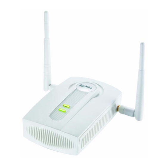
Page 27: Leds
Chapter 1 Introducing the NWA 1.7 LEDs Figure 10 LEDs Table 2 LEDs LABEL COLOR STATUS DESCRIPTION Green The NWA is receiving power and ready for use. Flashing There is system error and the NWA cannot boot up. The NWA is not receiving power. WLAN Green The wireless adaptor WLAN is active. - Page 28 Chapter 1 Introducing the NWA NWA1100-N User’s Guide...
-
Page 29: Introducing The Web Configurator
H A P T E R Introducing the Web Configurator This chapter describes how to access the NWA’s web configurator and provides an overview of its screens. 2.1 Accessing the Web Configurator Make sure your hardware is properly connected and prepare your computer or computer network to connect to the NWA (refer to the Quick Start Guide). -
Page 30: Resetting The Nwa
Chapter 2 Introducing the Web Configurator You should now see the Status screen. See Chapter 2 on page 29 for details about the Status screen. Note: The management session automatically times out when the time period set in the Administrator Inactivity Timer field expires (default five minutes). Simply log back into the NWA if this happens. - Page 31 Chapter 2 Introducing the Web Configurator Check the status bar at the bottom of the screen when you click Apply or OK to verify that the configuration has been updated. Figure 14 Status Screen of the Web Configurator • Click the links on the left of the screen to configure advanced features such as SYSTEM (General, Password and Time), WIRELESS (Wireless Settings, SSID, Security, RADIUS, MAC Filter), IP, REMOTE MGNT (Telnet, FTP, WWW and SNMP), CERTIFICATES, and LOGS (View Log and Log Settings).
- Page 32 Chapter 2 Introducing the Web Configurator NWA1100-N User’s Guide...
-
Page 33: Status Screens
H A P T E R Status Screens The Status screens display when you log into the NWA, or click Status in the navigation menu. Use the Status screens to look at the current status of the device, system resources, and interfaces. - Page 34 Chapter 3 Status Screens Table 3 The Status Screen (continued) LABEL DESCRIPTION Device Name This field displays the NWA system name. It is used for identification. You can change this in the System > General screen’s Device Name field. WLAN Operation This field displays the current operating mode of the first wireless module Mode (Access Point, Bridge/Repeater, AP+Bridge, Wireless Client, or...
-
Page 35: System Statistics Screen
Chapter 3 Status Screens Table 3 The Status Screen (continued) LABEL DESCRIPTION This field displays the number of wireless clients currently associated to the first wireless module. Each wireless module supports up to 32 concurrent associations. WLAN This field displays the number of wireless clients currently associated to the second wireless module. - Page 36 Chapter 3 Status Screens NWA1100-N User’s Guide...
-
Page 37: Tutorial
H A P T E R Tutorial This chapter first provides an overview of how to configure the wireless LAN on your NWA, and then gives step-by-step guidelines showing how to configure your NWA for some example scenarios. 4.1 How to Configure the Wireless LAN This section illustrates how to choose which wireless operating mode to use on the NWA and how to set up the wireless LAN in each wireless mode. -
Page 38: Further Reading
Chapter 4 Tutorial (see your Quick Start Guide for information on setting up your NWA and accessing the Web Configurator). Select the WLAN Adaptor you want to configure. Select Operation Mode. Access Point Bridge / Repeater MBSSID Wireless Client AP + Bridge Select Wireless Mode, Select Wireless Mode, Select Wireless Mode,... -
Page 39: How To Configure Multiple Wireless Networks
Chapter 4 Tutorial 4.2 How to Configure Multiple Wireless Networks In this example, you have been using your NWA as an access point for your office network (See your Quick Start Guide for information on how to set up your NWA in Access Point mode). Now your network is expanding and you want to make use of the MBSSID feature (see Section 8.2.4 on page 139) to provide multiple wireless networks. -
Page 40: Configure The Ssid Profiles
Chapter 4 Tutorial The standard network (SSID01) has access to all resources. The VoIP network (VoIP_SSID) has access to all resources and a high QoS priority. The guest network (Guest_SSID) has access to the Internet and the network printer only, and a low QoS priority. To configure these settings, you need to know the Media Access Control (MAC) addresses of the devices you want to allow users of the guest network to access. -
Page 41: Mbssid
Chapter 4 Tutorial 4.2.1.1 MBSSID Go to Wireless > Wireless Settings. Select MBSSID from the Operating Mode drop-down list box. SSID01 is the standard network, so select SSID01 as the first profile. It is always active. Select VoIP_SSID as the second profile, and Guest_SSID as the third profile. Select the corresponding Active check-boxes. -
Page 42: Configure The Standard Network
Chapter 4 Tutorial 4.2.2 Configure the Standard Network Click Wireless > SSID. Select SSID01 and click Edit. Select SecProfile1 as SSID01’s security profile. Select the Hidden SSID checkbox as you want only authorized company employees to use this network, so there is no need to broadcast the SSID to wireless clients scanning the area. -
Page 43: Configure The Voip Network
Chapter 4 Tutorial Next, click Wireless > Security. Select SecProfile1 and click Edit. Since SSID01 is the standard network that has access to all resources, assign a more secure security mode. Select WPA2-PSK-MIX as the Security Mode, and enter the Pre-Shared Key. In this example, use ThisisSSID01PreSharedKey. - Page 44 Chapter 4 Tutorial Select SecProfile2 as the Security Profile for the VoIP network. Select the Hidden SSID check- box. Select WMM-Voice in the QoS field to give VoIP the highest priority in the wireless network. Click Save. Next, click Wireless > Security. Select SecProfile2 and click Edit. Select WPA2-PSK as the Security Mode, and enter the Pre-Shared Key.
-
Page 45: Configure The Guest Network
Chapter 4 Tutorial 4.2.4 Configure the Guest Network When you are setting up the wireless network for guests to your office, your primary concern is to keep your network secure while allowing access to certain resources (such as a network printer, or the Internet). -
Page 46: Testing The Wireless Networks
Chapter 4 Tutorial Next, click Wireless > Security. Select SecProfile3 and click Edit. Select WPA-PSK in the Security Mode field. WPA-PSK provides strong security that is supported by most wireless clients. Even though your Guest_SSID clients do not have access to sensitive information on the network, you should not leave the network without security. -
Page 47: Nwa Setup In Ap And Wireless Client Modes
Chapter 4 Tutorial 4.3 NWA Setup in AP and Wireless Client Modes This example shows you how to restrict wireless access to your NWA. 4.3.1 Scenario In the figure below, there are two NWAs (A and B) in the network. A is in Access Point (AP) mode while station B is in Wireless Client mode. - Page 48 Chapter 4 Tutorial Log into the Web Configurator on NWA (A) and go to the Wireless > Wireless Settings screen. Set the Operation Mode to Access Point. Select the Wireless Mode. In this example, select 802.11b/g. Select Profile1 as the SSID Profile. Choose the Channel you want NWA (A) to use.
- Page 49 Chapter 4 Tutorial Go to Wireless > SSID. Select Profile1 and click Edit. Change the SSID to AP-A. Select SecProfile1 in the Security field. Select the check-box for Enable Intra-BSS Traffic blocking so the client cannot access other clients on the same wireless network. 10 Click Save.
-
Page 50: Configuring The Nwa In Wireless Client Mode
Chapter 4 Tutorial 12 Configure WPA-PSK as the Security Mode and enter ThisisMyPreSharedKey in the Pre- Shared Key field. 13 Click Apply to finish configuration for NWA (A). 4.3.3 Configuring the NWA in Wireless Client Mode The NWA (B) should have a wired connection before it can be set to wireless client operating mode. Connect your NWA to the FTP server. -
Page 51: Mac Filter Setup
Chapter 4 Tutorial Find and select NWA1100-N-A’s SSID: NWA-1100-A. Click Selected. Go to Wireless > Security to configure the NWA to use the same security mode and Pre-Shared Key as NWA1100-N-A: WPA-PSK/ThisisMyPreSharedKey. Click Apply. Figure 18 4.3.4 MAC Filter Setup... -
Page 52: Testing The Connection And Troubleshooting
Chapter 4 Tutorial Select Allow Listed in the Access Control Mode field. Enter the MAC addresses of the wireless clients (W, Y and Z) you want to associate with the NWA. Click Apply. Now, only the authorized wireless clients (W, Y and Z) can access the FTP server. 4.3.5 Testing the Connection and Troubleshooting This section discusses how you can check if you have correctly configured your network setup as described in this tutorial. -
Page 53: Technical Reference
Technical Reference The appendices provide general information. Some details may not apply to your NWA. -
Page 55: System Screens
H A P T E R System Screens 5.1 Overview This chapter provides information and instructions on how to identify and manage your NWA over the network. Figure 19 NWA Setup In the figure above, the NWA connects to a Domain Name Server (DNS) server to avail of a domain name. - Page 56 Chapter 5 System Screens to the hosts without problems. However, the Internet Assigned Numbers Authority (IANA) has reserved the following three blocks of IP addresses specifically for private networks. Table 6 Private IP Address Ranges 10.0.0.0 10.255.255.255 172.16.0.0 172.31.255.255 192.168.0.0 192.168.255.255 You can obtain your IP address from the IANA, from an ISP or have it assigned by a private network.
-
Page 57: General Screen
Chapter 5 System Screens 5.4 General Screen Use the General screen to identify your NWA over the network. Click System > General. The following screen displays. Figure 20 System > General The following table describes the labels in this screen. Table 7 System >... -
Page 58: Time Screen
Chapter 5 System Screens The following table describes the labels in this screen. Table 8 System > Password LABEL DESCRIPTIONS Current Password Type in your existing system password. New Password Type your new system password (max 19 characters). Note that as you type a password, the screen displays an asterisk (*) for each character you type. -
Page 59: Technical Reference
Chapter 5 System Screens Table 9 System > Time (continued) LABEL DESCRIPTION Manual IP Enter the IP address or URL of your time server. Check with your ISP/ network administrator if you are unsure of this information. Time Zone Setup Time Zone Choose the time zone of your location. -
Page 60: Wireless Settings Screen
H A P T E R Wireless Settings Screen 6.1 Overview This chapter discusses the steps to configure the Wireless Settings screen on the NWA. It also introduces the wireless LAN (WLAN) and some basic scenarios. Figure 23 Wireless Mode In the figure above, the NWA allows access to another bridge device (A) and a notebook computer (B) upon verifying their settings and credentials. -
Page 61: What You Need To Know
Chapter 6 Wireless Settings Screen 6.3 What You Need To Know A Basic Service Set (BSS) exists when all communications between wireless clients or between a wireless client and a wired network client go through one access point (AP). Intra-BSS traffic is traffic between wireless clients in the BSS. -
Page 62: Wireless Settings Screen
Chapter 6 Wireless Settings Screen Wireless Mode The IEEE 802.1x standard was designed to extend the features of IEEE 802.11 to support extended authentication as well as providing additional accounting and control features. Your NWA can support 802.11b/g and 802.11b/g/n. MBSSID Traditionally, you needed to use different APs to configure different Basic Service Sets (BSSs). -
Page 63: Access Point Mode
Chapter 6 Wireless Settings Screen 6.4.1 Access Point Mode Use this screen to use your NWA as an access point. Select Access Point as the Operation Mode. The following screen displays. Figure 24 Wireless > Wireless Settings: Access Point The following table describes the general wireless LAN labels in this screen. Table 11 Wireless >... - Page 64 Chapter 6 Wireless Settings Screen Table 11 Wireless > Wireless Settings: Access Point (continued) LABEL DESCRIPTION SSID Profile The SSID (Service Set IDentifier) identifies the Service Set with which a wireless station is associated. Wireless stations associating to the access point (AP) must have the same SSID.
-
Page 65: Bridge / Repeater Mode
Chapter 6 Wireless Settings Screen Table 11 Wireless > Wireless Settings: Access Point (continued) LABEL DESCRIPTION Rates This section controls the data rates permitted for clients. Configuration For each Rate, select an option from the Configuration list. The options are: •... - Page 66 Chapter 6 Wireless Settings Screen Use this screen to use the NWA as a wireless bridge. Select Bridge/Repeater as the Operation Mode. Figure 25 Wireless > Wireless Settings: Bridge/Repeater The following table describes the bridge labels in this screen. Table 12 Wireless > Wireless Settings: Bridge/Repeater LABEL DESCRIPTIONS Basic Settings...
- Page 67 Chapter 6 Wireless Settings Screen Table 12 Wireless > Wireless Settings: Bridge/Repeater (continued) LABEL DESCRIPTIONS SSID Profile The SSID (Service Set IDentifier) identifies the Service Set with which a wireless station is associated. Wireless stations associating to the access point (AP) must have the same SSID. Select an SSID Profile from the drop- down list box.
- Page 68 Chapter 6 Wireless Settings Screen Table 12 Wireless > Wireless Settings: Bridge/Repeater (continued) LABEL DESCRIPTIONS Rates Configuration This section controls the data rates permitted for clients. For each Rate, select an option from the Configuration list. The options are: • Basic (1~11 Mbps only): Clients can always connect to the access point at this speed.
-
Page 69: Ap + Bridge Mode
Chapter 6 Wireless Settings Screen 6.4.3 AP + Bridge Mode Use this screen to have the NWA function as a bridge and access point simultaneously. Select AP+Bridge as the Operation Mode. The following screen displays. Figure 26 Wireless > Wireless Settings: AP+Bridge See the tables describing the fields in the Access Point and Bridge / Repeater operating modes for descriptions of the fields in this screen. -
Page 70: Wireless Client Mode
Chapter 6 Wireless Settings Screen 6.4.4 Wireless Client Mode Use this screen to turn your NWA into a wireless client. Select Wireless Client as the Operation Mode. The following screen displays. Figure 27 Wireless > Wireless Settings: Wireless Client The following table describes the general wireless LAN labels in this screen. Table 13 Wireless >... - Page 71 Chapter 6 Wireless Settings Screen Table 13 Wireless > Wireless Settings: Wireless Client (continued) LABEL DESCRIPTION SSID Profile The SSID (Service Set IDentifier) identifies the Service Set with which a wireless station is associated. Wireless stations associating to the access point (AP) must have the same SSID.
- Page 72 Chapter 6 Wireless Settings Screen Table 13 Wireless > Wireless Settings: Wireless Client (continued) LABEL DESCRIPTION A-MPDU This field is available only when 802.11 b/g/n is selected as the Wireless aggregation Mode. Select Enable to allow the grouping of several A-MSDUs (Aggregate MAC Service Data Units) into one large A-MPDU (Aggregate MAC Protocol Data Unit).
-
Page 73: Mbssid Mode
Chapter 6 Wireless Settings Screen 6.4.5 MBSSID Mode Use this screen to have the NWA function in MBSSID mode. Select MBSSID as the Operating Mode. The following screen diplays. Figure 28 Wireless > Wireless Settings: MBSSID The following table describes the labels in this screen. Table 14 Wireless >... - Page 74 Chapter 6 Wireless Settings Screen Table 14 Wireless > Wireless Settings: MBSSID (continued) LABEL DESCRIPTION Channel Width This field displays only when you select 802.11 b/g/n in the 802.11 Wireless Mode field. A standard 20MHz channel offers transfer speeds of up to 150Mbps whereas a 40MHz channel uses two standard channels and offers speeds of up to 300Mbps.
-
Page 75: Technical Reference
Chapter 6 Wireless Settings Screen Table 14 Wireless > Wireless Settings: MBSSID (continued) LABEL DESCRIPTION Extension channel You can use CTS to self or RTS-CTS protection mechanism to reduce protection mode conflicts with other wireless networks or hidden wireless clients. The throughput of RTS-CTS is much lower than CTS to self. -
Page 76: Spanning Tree Protocol (Stp)
Chapter 6 Wireless Settings Screen On APs without WMM QoS, all traffic streams are given the same access priority to the wireless network. If the introduction of another traffic stream creates a data transmission demand that exceeds the current network capacity, then the new traffic stream reduces the throughput of the other traffic streams. -
Page 77: How Stp Works
Chapter 6 Wireless Settings Screen 6.5.2.3 How STP Works After a bridge determines the lowest cost-spanning tree with STP, it enables the root port and the ports that are the designated ports for connected LANs, and disables all other ports that participate in STP. - Page 78 Chapter 6 Wireless Settings Screen TERM DESCRIPTION Fragmentation A small fragmentation threshold is recommended for busy networks, while a Threshold larger threshold provides faster performance if the network is not very busy. Roaming If you have two or more NWAs (or other wireless access points) on your wireless network, you can enable this option so that wireless devices can change locations without having to log in again.
-
Page 79: Ssid Screen
H A P T E R SSID Screen 7.1 Overview This chapter describes how you can configure Service Set Identifier (SSID) profiles in your NWA. Figure 29 Sample SSID Profiles In the figure above, the NWA has three SSID profiles configured: a standard profile (SSID01), a profile with high QoS settings for Voice over IP (VoIP) users (VoIP_SSID), and a guest profile that allows visitors access only the Internet and the network printer (Guest_SSID). -
Page 80: The Ssid Screen
Chapter 7 SSID Screen To configure the settings of your SSID profile, you need to know the Media Access Control (MAC) addresses of the devices you want to allow access to it. Each SSID profile references the settings configured in the following screens: •... -
Page 81: Configuring Ssid
Chapter 7 SSID Screen Figure 31 Wireless > SSID (continued) LABEL DESCRIPTION Profile Name This field displays the identification name of each SSID profile on the NWA. SSID This field displays the name of the wireless profile on the network. When a wireless client scans for an AP to associate with, this is the name that is broadcast and seen in the wireless client utility. -
Page 82: Technical Reference
Chapter 7 SSID Screen The following table describes the labels in this screen. Table 18 SSID: Edit LABEL DESCRIPTION Profile Name This is the name that identifying this profile. SSID When a wireless client scans for an AP to associate with, this is the name that is broadcast and seen in the wireless client utility. -
Page 83: Wmm Qos Priorities
Chapter 7 SSID Screen On APs without WMM QoS, all traffic streams are given the same access priority to the wireless network. If the introduction of another traffic stream creates a data transmission demand that exceeds the current network capacity, then the new traffic stream reduces the throughput of the other traffic streams. - Page 84 Chapter 7 SSID Screen Table 20 ToS and IEEE 802.1d to WMM QoS Priority Level Mapping Dscp Value WMM qos Priority Level 96, 0 besteffort 64, 32 background A. The NWA also uses best effort for any DSCP value for which another WMM QoS priority is not specified (255, 158 or 37 for example).
-
Page 85: Wireless Security Screen
H A P T E R Wireless Security Screen 8.1 Overview This chapter describes how to use the Wireless Security screen. This screen allows you to configure the security mode for your NWA. Wireless security is vital to your network. It protects communications between wireless stations, access points and the wired network. -
Page 86: What You Need To Know
Chapter 8 Wireless Security Screen 8.3 What You Need To Know User Authentication Authentication is the process of verifying whether a wireless device is allowed to use the wireless network. You can make every user log in to the wireless network before they can use it. However, every device in the wireless network has to support IEEE 802.1x to do this. -
Page 87: The Security Screen
Chapter 8 Wireless Security Screen • WPA2-PSK. This adds a pre-shared key on top of WPA2 standard. • WPA2-PSK-MIX. This commands the NWA to use either WPA-PSK or WPA2-PSK depending on which security mode the wireless client uses. Note: In Bridge/Repeater and AP+Bridge operating modes, the only available security modes are WEP, WPA-PSK, and WPA2-PSK. - Page 88 Chapter 8 Wireless Security Screen Click Wireless > Security. Select the profile that you want to configure and click Edit. Figure 34 Wireless > Security The Security Settings screen varies depending upon the security mode you select. Figure 35 Security: None Note that some screens display differently depending on the operating mode selected in the Wireless >...
-
Page 89: Security: Wep
Chapter 8 Wireless Security Screen 8.4.1 Security: WEP Use this screen to use WEP as the security mode for your NWA. Select WEP in the Security Mode field to display the following screen. Figure 36 Security: WEP The following table describes the labels in this screen. Table 22 Security: WEP LABEL DESCRIPTION... -
Page 90: Security: 802.1X Only
Chapter 8 Wireless Security Screen Table 22 Security: WEP (continued) LABEL DESCRIPTION Reset Click Reset to begin configuring this screen afresh. Back Click Back to return to the previous screen. 8.4.2 Security: 802.1x Only This screen varies depending on whether you select Access Point or Wireless Client in the Wireless >... -
Page 91: Wireless Client
Chapter 8 Wireless Security Screen Table 23 Security: 802.1x Only for Access Point (continued) LABEL DESCRIPTION Reset Click Reset to begin configuring this screen afresh. Back Click Back to return to the previous screen. 8.4.2.2 Wireless Client Use this screen to use 802.1x-Only security mode for your NWA that is in Wireless Client operating mode. -
Page 92: Security: 802.1X Static 64-Bit, 802.1X Static 128-Bit, 802.1X Static 152-Bit
Chapter 8 Wireless Security Screen 8.4.3 Security: 802.1x Static 64-bit, 802.1x Static 128-bit, 802.1x Static 152- Use this screen to use 802.1x Static 64, 802.1x Static 128, or 802.1x Static 152 security mode for your NWA. Select 802.1x Static 64, 802.1x Static 128, or 802.1x Static 152 in the Security Mode field to display the following screen. -
Page 93: Security: Wpa
Chapter 8 Wireless Security Screen Table 25 Security: 802.1x Static 64-bit, 802.1x Static 128-bit, 802.1x Static 152-bit (continued) LABEL DESCRIPTION Key 1 to Key 4 If you chose 802.1x Static 64, then enter any 5 characters (ASCII string) or 10 hexadecimal characters ("0-9", "A-F") preceded by 0x for each key. -
Page 94: Wireless Client
Chapter 8 Wireless Security Screen The following table describes the labels in this screen. Table 26 Security: WPA for Access Point LABEL DESCRIPTION Security Settings Profile Name This is the name that identifying this profile. Security Mode Choose WPA in this field. Rekey Options ReAuthentication Specify how often wireless stations have to resend user names and passwords in... -
Page 95: Security: Wpa2 Or Wpa2-Mix
Chapter 8 Wireless Security Screen The following table describes the labels in this screen. Table 27 Security: WPA for Wireless Client LABEL DESCRIPTION Security Settings Profile Name This is the name that identifying this profile. Security Mode Choose the same security mode used by the AP. Data Encryption Select between None and TKIP. -
Page 96: Wireless Client
Chapter 8 Wireless Security Screen The following table describes the labels not previously discussed Table 28 Security: WPA2 or WPA2-MIX for Access Point LABEL DESCRIPTIONS Security Settings Profile Name This is the name that identifying this profile. Security Mode Choose WPA2 or WPA2-MIX in this field. Rekey Options ReAuthentication Specify how often wireless stations have to resend usernames and passwords in... -
Page 97: Security: Wpa-Psk, Wpa2-Psk, Wpa2-Psk-Mix
Chapter 8 Wireless Security Screen The following table describes the labels in this screen. Table 29 Security: WPA2 or WPA2-MIX for Wireless Client LABEL DESCRIPTION Security Settings Profile Name This is the name that identifying this profile. Security Mode Choose the same security mode used by the AP. IEEE802.1x Authentication EAP Type The options on the left refer to EAP methods. -
Page 98: Technical Reference
Chapter 8 Wireless Security Screen Table 30 Security: WPA-PSK, WPA2-PSK or WPA2-PSK-MIX (continued) LABEL DESCRIPTION Reset Click Reset to begin configuring this screen afresh. Back Click Back to return to the previous screen. 8.5 Technical Reference This section provides technical background information on the topics discussed in this chapter. The following is a general guideline in choosing the security mode for your NWA. -
Page 99: Radius Screen
H A P T E R RADIUS Screen 9.1 Overview This chapter describes how you can use the Wireless > RADIUS screen. Remote Authentication Dial In User Service (RADIUS) is a protocol that can be used to manage user access to large networks. It is based on a client-server model that supports authentication, authorization and accounting. -
Page 100: The Radius Screen
Chapter 9 RADIUS Screen • Accounting which keeps track of the client’s network activity. RADIUS is a simple package exchange in which your AP acts as a message relay between the wireless client and the network RADIUS server. You should know the IP addresses, ports and share secrets of the external RADIUS server and/or the external RADIUS accounting server you want to use with your NWA. - Page 101 Chapter 9 RADIUS Screen Table 31 Wireless > RADIUS (continued) LABEL DESCRIPTION Active Select the check box to enable user authentication through an external authentication server. This check box is not available when you select Internal. RADIUS Server IP Enter the IP address of the external authentication server in dotted decimal Address notation.
-
Page 102: Mac Filter Screen
H A P T E R MAC Filter Screen 10.1 Overview This chapter discusses how you can use the Wireless > MAC Filter screen. The MAC filter function allows you to configure the NWA to grant access to the NWA from other wireless devices (Allow Association) or exclude devices from accessing the NWA (Deny Association). -
Page 103: Mac Filter Screen
Chapter 10 MAC Filter Screen 10.4 MAC Filter Screen Use this screen to enable MAC address filtering in your NWA. You can specify MAC addresses to either allow or deny association with your NWA. Click Wireless > MAC Filter. The screen displays as shown. - Page 104 Chapter 10 MAC Filter Screen The following table describes the labels in this screen. Table 32 Wireless > MAC Filter LABEL DESCRIPTION ProfileName This is the name that identifying this RADIUS. Access Control Mode Select Disable if you do not want to use this feature. Select Allow Listed to permit access to the NWA.
-
Page 105: Ip Screen
H A P T E R IP Screen 11.1 Overview This chapter describes how you can configure the IP address of your NWA. The Internet Protocol (IP) address identifies a device on a network. Every networking device (including computers, servers, routers, printers, etc.) needs an IP address to communicate across the network. -
Page 106: Ip Screen
Chapter 11 IP Screen 11.4 IP Screen Use this screen to configure the IP address for your NWA. Click IP to display the following screen. Figure 51 IP Setup The following table describes the labels in this screen. Table 33 IP Setup LABEL DESCRIPTION Obtain IP Address... -
Page 107: Technical Reference
Chapter 11 IP Screen 11.5 Technical Reference This section provides the technical background information about the topics covered in this chapter. 11.5.1 WAN IP Address Assignment Every computer on the Internet must have a unique IP address. If your networks are isolated from the Internet (only between your two branch offices, for instance) you can assign any IP addresses to the hosts without problems. -
Page 108: How Stp Works
Chapter 11 IP Screen Path cost is the cost of transmitting a frame onto a LAN through that port. It is assigned according to the speed of the link to which a port is attached. The slower the media, the higher the cost - see the following table. -
Page 109: Remote Management
H A P T E R Remote Management 12.1 Overview This chapter shows you how to enable remote management of your NWA. It provides information on determining which services or protocols can access which of the NWA’s interfaces. Remote Management allows a user to administrate the device over the network. You can manage your NWA from a remote location via the following interfaces: •... -
Page 110: What You Need To Know
Chapter 12 Remote Management • Use the WWW screen to configure through which interface(s) and from which IP address(es) you can use the Web Browser to manage the NWA (see Section 12.6 on page 113). • Use the SNMP screen to configure through which interface(s) and from which IP address(es) a network systems manager can access the NWA (see Section 12.7 on page 115). - Page 111 Chapter 12 Remote Management Note: SNMP is only available if TCP/IP is configured. Figure 53 SNMP Management Mode An SNMP managed network consists of two main types of component: agents and a manager. An agent is a management software module that resides in a managed device (the NWA). An agent translates the local management information from the managed device into a form compatible with SNMP.
-
Page 112: The Telnet Screen
Chapter 12 Remote Management timeout period. The management session does not time out when a statistics screen is polling. You can change the timeout period in the SYSTEM screen. 12.4 The Telnet Screen Use this screen to configure your NWA for remote Telnet access. You can use Telnet to access the NWA’s Command Line Interface (CLI). -
Page 113: The Www Screen
Chapter 12 Remote Management To change your NWA’s FTP settings, click REMOTE MGMT > FTP. The following screen displays. Figure 55 Remote Management: FTP The following table describes the labels in this screen. Table 38 Remote Management: FTP LABEL DESCRIPTION Server Port You may change the server port number for a service if needed, however you must use the same port number in order to use that service for remote... - Page 114 Chapter 12 Remote Management To change your NWA’s WWW settings, click REMOTE MGNT > WWW. The following screen shows. Figure 56 Remote Management: WWW The following table describes the labels in this screen. Table 39 Remote Management: WWW LABEL DESCRIPTION Server Port You may change the server port number for a service if needed, however you must use the same port number in order to use that service for remote...
-
Page 115: The Snmp Screen
Chapter 12 Remote Management 12.7 The SNMP Screen Use this screen to have a manager station administrate your NWA over the network. To change your NWA’s SNMP settings, click REMOTE MGMT > SNMP. The following screen displays. Figure 57 Remote Management: SNMP The following table describes the labels in this screen. -
Page 116: Technical Reference
12.8.2 Supported MIBs The NWA supports MIB II that is defined in RFC-1213 and RFC-1215 as well as the proprietary ZyXEL private MIB. The purpose of the MIBs is to let administrators collect statistical data and monitor status and performance. -
Page 117: Snmp Traps
RFC 1907) must be enabled on in order for the device to send authenticationFailure traps. Use a MIB browser to enable or disable snmpEnableAuthenTraps. Traps defined in the ZyXEL Private MIB. whyReboot 1.3.6.1.4.1.890.1.5.13.0. This trap is sent with the reason for restarting before the system reboots (warm start). - Page 118 Chapter 12 Remote Management NWA1100-N User’s Guide...
-
Page 119: Certificate Screen
H A P T E R Certificate Screen 13.1 Overview This chapter describes how your NWA can use certificates as a means of authenticating wireless clients. It gives background information about public-key certificates and explains how to use them. A certificate contains the certificate owner’s identity and public key. Certificates provide a way to exchange public keys for use in authentication. -
Page 120: Certificate Screen
Chapter 13 Certificate Screen 13.4 Certificate Screen Use this screen to view, delete and import certificates. Click CERTIFICATE to open the NWA’s summary list of certificates and to import a new certificate. See the following figure. Figure 59 Certificate The following table describes the labels in this screen. Table 43 Certificate LABEL DESCRIPTION... -
Page 121: Certification Authorities
Chapter 13 Certificate Screen These keys work like a handwritten signature (in fact, certificates are often referred to as “digital signatures”). Only you can write your signature exactly as it should look. When people know what your signature looks like, they can verify whether something was signed by you, or by someone else. - Page 122 Chapter 13 Certificate Screen Double-click the certificate’s icon to open the Certificate window. Click the Details tab and scroll down to the Thumbprint Algorithm and Thumbprint fields. Figure 61 Certificate Details Use a secure method to verify that the certificate owner has the same information in the Thumbprint Algorithm and Thumbprint fields.
-
Page 123: Log Screens
H A P T E R Log Screens 14.1 Overview This chapter provides information on viewing and generating logs on your NWA. Logs are files that contain recorded network activity over a set period. They are used by administrators to monitor the health of the system(s) they are managing. Logs enable administrators to effectively monitor events, errors, progress, etc. -
Page 124: What You Need To Know
Chapter 14 Log Screens 14.3 What You Need To Know Alerts and Logs An alert is a type of log that warrants more serious attention. Some categories such as System Errors consist of both logs and alerts. You can differentiate them by their color in the View Log screen. -
Page 125: Log Settings Screen
Chapter 14 Log Screens The following table describes the labels in this screen. Table 44 View Log LABEL DESCRIPTION Time This field displays the time the log was recorded. Source This field lists the source IP address and the port number of the incoming packet. - Page 126 Chapter 14 Log Screens The following table describes the labels in this screen. Table 45 Log Settings LABEL DESCRIPTION Address Info Mail Server Enter the server name or the IP address of the mail server for the e-mail addresses specified below. If this field is left blank, logs and alert messages will not be sent via e-mail.
- Page 127 Chapter 14 Log Screens Table 45 Log Settings (continued) LABEL DESCRIPTION Apply Click Apply to save your customized settings and exit this screen. Reset Click Reset to reconfigure all the fields in this screen. NWA1100-N User’s Guide...
- Page 128 Chapter 14 Log Screens NWA1100-N User’s Guide...
-
Page 129: Maintenance
135). 15.3 What You Need To Know You can find the firmware for your device at www.zyxel.com. It is a file that (usually) uses the system model name with a "*.bin" extension, for example "[Model #].bin". The upload process uses HTTP (Hypertext Transfer Protocol) and may take up to two minutes. -
Page 130: Channel Usage Screen
Chapter 15 Maintenance Click Maintenance > Association List. The following screen displays. Figure 65 Association List The following table describes the labels in this screen. Table 46 Association List LABEL DESCRIPTION This is the index number of an associated wireless station. MAC Address This field displays the MAC address of an associated wireless station. -
Page 131: F/W Upload Screen
Chapter 15 Maintenance The following table describes the labels in this screen. Table 47 Channel Usage LABEL DESCRIPTION SSID This is the Service Set IDentification name of the AP in an Infrastructure wireless network or wireless station in an Ad-Hoc wireless network. For our purposes, we define an Infrastructure network as a wireless network that uses an AP and an Ad-Hoc network (also known as Independent Basic Service Set (IBSS)) as one that doesn’t. - Page 132 Chapter 15 Maintenance The following table describes the labels in this screen. Table 48 Firmware Upload LABEL DESCRIPTION File Path Type in the location of the file you want to upload in this field or click Browse ... to find it. Browse...
-
Page 133: Configuration File Screen
Chapter 15 Maintenance 15.7 Configuration File Screen Use this screen to backup, restore and reset the configuration of your NWA. Click Maintenance > Configuration File. The screen appears as shown next. Figure 71 Configuration File 15.7.1 Backup Configuration Backup configuration allows you to back up (save) the NWA’s current configuration to a file on your computer. - Page 134 Chapter 15 Maintenance Do not turn off the NWA while configuration file upload is in progress. After you see a “restore configuration successful” screen, you must then wait one minute before logging into the NWA again. Figure 72 Configuration Upload Successful The NWA automatically restarts in this time causing a temporary network disconnect.
-
Page 135: Back To Factory Defaults
Chapter 15 Maintenance 15.7.3 Back to Factory Defaults Pressing the Reset button in this section clears all user-entered configuration information and returns the NWA to its factory defaults as shown on the screen. The following warning screen will appear. Figure 75 Reset Warning Message You can also press the RESET button to reset your NWA to its factory default settings. - Page 136 Chapter 15 Maintenance NWA1100-N User’s Guide...
-
Page 137: Troubleshooting
H A P T E R Troubleshooting This chapter offers some suggestions to solve problems you might encounter. The potential problems are divided into the following categories. • Power, Hardware Connections, and LEDs • NWA Access and Login • Internet Access 16.1 Power, Hardware Connections, and LEDs The NWA does not turn on. -
Page 138: Nwa Access And Login
Chapter 16 Troubleshooting 16.2 NWA Access and Login I forgot the IP address for the NWA. The default IP address is 192.168.1.2. If you changed the IP address and have forgotten it, you might get the IP address of the NWA by looking up the IP address of the default gateway for your computer. -
Page 139: Internet Access
Chapter 16 Troubleshooting If the problem continues, contact the network administrator or vendor, or try one of the advanced suggestions. Advanced Suggestions • Try to access the NWA using another service, such as Telnet. If you can access the NWA, check the remote management settings to find out why the NWA does not respond to HTTP. - Page 140 Chapter 16 Troubleshooting I cannot access the Internet anymore. I had access to the Internet (with the NWA), but my Internet connection is not available anymore. Check the hardware connections, and make sure the LEDs are behaving as expected. See the Quick Start Guide and Section 1.7 on page Reboot the NWA.
-
Page 141: Appendix A Product Specifications
P P E N D I X Product Specifications The following tables summarize the NWA’s hardware and firmware features. Table 50 Hardware Specifications Power Specification 12 V DC, 1.5 A Reset button Returns all settings to their factory defaults. Ethernet Port •... - Page 142 Appendix A Power over Ethernet (PoE) Specifications Table 51 Firmware Specifications (continued) SSL Passthrough SSL (Secure Sockets Layer) uses a public key to encrypt data that's transmitted over an SSL connection. Both Netscape Navigator and Internet Explorer support SSL, and many Web sites use the protocol to obtain confidential user information, such as credit card numbers.
-
Page 143: Appendix B Setting Up Your Computer's Ip Address
P P E N D I X Setting Up Your Computer’s IP Address Note: Your specific NWA may not support all of the operating systems described in this appendix. See the product specifications for more information about which operating systems are supported. This appendix shows you how to configure the IP settings on your computer in order for it to be able to communicate with the other devices on your network. - Page 144 Appendix B Setting Up Your Computer’s IP Address Click Start > Control Panel. In the Control Panel, click the Network Connections icon. Right-click Local Area Connection and then select Properties. NWA1100-N User’s Guide...
- Page 145 Appendix B Setting Up Your Computer’s IP Address On the General tab, select Internet Protocol (TCP/IP) and then click Properties. NWA1100-N User’s Guide...
- Page 146 Appendix B Setting Up Your Computer’s IP Address The Internet Protocol TCP/IP Properties window opens. Select Obtain an IP address automatically if your network administrator or ISP assigns your IP address dynamically. Select Use the following IP Address and fill in the IP address, Subnet mask, and Default gateway fields if you have a static IP address that was assigned to you by your network administrator or ISP.
- Page 147 Appendix B Setting Up Your Computer’s IP Address Windows Vista This section shows screens from Windows Vista Professional. Click Start > Control Panel. In the Control Panel, click the Network and Internet icon. Click the Network and Sharing Center icon. NWA1100-N User’s Guide...
- Page 148 Appendix B Setting Up Your Computer’s IP Address Click Manage network connections. Right-click Local Area Connection and then select Properties. Note: During this procedure, click Continue whenever Windows displays a screen saying that it needs your permission to continue. NWA1100-N User’s Guide...
- Page 149 Appendix B Setting Up Your Computer’s IP Address Select Internet Protocol Version 4 (TCP/IPv4) and then select Properties. NWA1100-N User’s Guide...
- Page 150 Appendix B Setting Up Your Computer’s IP Address The Internet Protocol Version 4 (TCP/IPv4) Properties window opens. Select Obtain an IP address automatically if your network administrator or ISP assigns your IP address dynamically. Select Use the following IP Address and fill in the IP address, Subnet mask, and Default gateway fields if you have a static IP address that was assigned to you by your network administrator or ISP.
- Page 151 Appendix B Setting Up Your Computer’s IP Address Windows 7 This section shows screens from Windows 7 Enterprise. Click Start > Control Panel. In the Control Panel, click View network status and tasks under the Network and Internet category. Click Change adapter settings. NWA1100-N User’s Guide...
- Page 152 Appendix B Setting Up Your Computer’s IP Address Double click Local Area Connection and then select Properties. Note: During this procedure, click Continue whenever Windows displays a screen saying that it needs your permission to continue. NWA1100-N User’s Guide...
- Page 153 Appendix B Setting Up Your Computer’s IP Address Select Internet Protocol Version 4 (TCP/IPv4) and then select Properties. NWA1100-N User’s Guide...
- Page 154 Appendix B Setting Up Your Computer’s IP Address The Internet Protocol Version 4 (TCP/IPv4) Properties window opens. Select Obtain an IP address automatically if your network administrator or ISP assigns your IP address dynamically. Select Use the following IP Address and fill in the IP address, Subnet mask, and Default gateway fields if you have a static IP address that was assigned to you by your network administrator or ISP.
- Page 155 Appendix B Setting Up Your Computer’s IP Address The IP settings are displayed as follows. Mac OS X: 10.3 and 10.4 The screens in this section are from Mac OS X 10.4 but can also apply to 10.3. Click Apple > System Preferences. NWA1100-N User’s Guide...
- Page 156 Appendix B Setting Up Your Computer’s IP Address In the System Preferences window, click the Network icon. When the Network preferences pane opens, select Built-in Ethernet from the network connection type list, and then click Configure. NWA1100-N User’s Guide...
- Page 157 Appendix B Setting Up Your Computer’s IP Address For dynamically assigned settings, select Using DHCP from the Configure IPv4 list in the TCP/IP tab. For statically assigned settings, do the following: • From the Configure IPv4 list, select Manually. • In the IP Address field, type your IP address. •...
- Page 158 Appendix B Setting Up Your Computer’s IP Address Verifying Settings Check your TCP/IP properties by clicking Applications > Utilities > Network Utilities, and then selecting the appropriate Network Interface from the Info tab. Figure 77 Mac OS X 10.4: Network Utility Mac OS X: 10.5 and 10.6 The screens in this section are from Mac OS X 10.5 but can also apply to 10.6.
- Page 159 Appendix B Setting Up Your Computer’s IP Address In System Preferences, click the Network icon. When the Network preferences pane opens, select Ethernet from the list of available connection types. From the Configure list, select Using DHCP for dynamically assigned settings. For statically assigned settings, do the following: NWA1100-N User’s Guide...
- Page 160 Appendix B Setting Up Your Computer’s IP Address • From the Configure list, select Manually. • In the IP Address field, enter your IP address. • In the Subnet Mask field, enter your subnet mask. • In the Router field, enter the IP address of your NWA. Click Apply and close the window.
- Page 161 Appendix B Setting Up Your Computer’s IP Address Verifying Settings Check your TCP/IP properties by clicking Applications > Utilities > Network Utilities, and then selecting the appropriate Network interface from the Info tab. Figure 78 Mac OS X 10.5: Network Utility Linux: Ubuntu 8 (GNOME) This section shows you how to configure your computer’s TCP/IP settings in the GNU Object Model Environment (GNOME) using the Ubuntu 8 Linux distribution.
- Page 162 Appendix B Setting Up Your Computer’s IP Address When the Network Settings window opens, click Unlock to open the Authenticate window. (By default, the Unlock button is greyed out until clicked.) You cannot make changes to your configuration unless you first enter your admin password. In the Authenticate window, enter your admin account name and password then click the Authenticate button.
- Page 163 Appendix B Setting Up Your Computer’s IP Address In the Network Settings window, select the connection that you want to configure, then click Properties. The Properties dialog box opens. • In the Configuration list, select Automatic Configuration (DHCP) if you have a dynamic IP address.
- Page 164 Appendix B Setting Up Your Computer’s IP Address If you know your DNS server IP address(es), click the DNS tab in the Network Settings window and then enter the DNS server information in the fields provided. Click the Close button to apply the changes. NWA1100-N User’s Guide...
- Page 165 Appendix B Setting Up Your Computer’s IP Address Verifying Settings Check your TCP/IP properties by clicking System > Administration > Network Tools, and then selecting the appropriate Network device from the Devices tab. The Interface Statistics column shows data if your connection is working properly. Figure 79 Ubuntu 8: Network Tools Linux: openSUSE 10.3 (KDE) This section shows you how to configure your computer’s TCP/IP settings in the K Desktop...
- Page 166 Appendix B Setting Up Your Computer’s IP Address Click K Menu > Computer > Administrator Settings (YaST). When the Run as Root - KDE su dialog opens, enter the admin password and click OK. NWA1100-N User’s Guide...
- Page 167 Appendix B Setting Up Your Computer’s IP Address When the YaST Control Center window opens, select Network Devices and then click the Network Card icon. When the Network Settings window opens, click the Overview tab, select the appropriate connection Name from the list, and then click the Configure button. NWA1100-N User’s Guide...
- Page 168 Appendix B Setting Up Your Computer’s IP Address When the Network Card Setup window opens, click the Address tab Figure 80 openSUSE 10.3: Network Card Setup Select Dynamic Address (DHCP) if you have a dynamic IP address. Select Statically assigned IP Address if you have a static IP address. Fill in the IP address, Subnet mask, and Hostname fields.
- Page 169 Appendix B Setting Up Your Computer’s IP Address If you know your DNS server IP address(es), click the Hostname/DNS tab in Network Settings and then enter the DNS server information in the fields provided. Click Finish to save your settings and close the window. Verifying Settings Click the KNetwork Manager icon on the Task bar to check your TCP/IP properties.
- Page 170 Appendix B Setting Up Your Computer’s IP Address When the Connection Status - KNetwork Manager window opens, click the Statistics tab to see if your connection is working properly. Figure 82 openSUSE: Connection Status - KNetwork Manager NWA1100-N User’s Guide...
-
Page 171: Appendix C Pop-Up Windows, Javascript And Java Permissions
P P E N D I X Pop-up Windows, JavaScript and Java Permissions In order to use the web configurator you need to allow: • Web browser pop-up windows from your device. • JavaScript (enabled by default). • Java permissions (enabled by default). Note: The screens used below belong to Internet Explorer version 6, 7 and 8. - Page 172 Appendix C Pop-up Windows, JavaScript and Java Permissions Clear the Block pop-ups check box in the Pop-up Blocker section of the screen. This disables any web pop-up blockers you may have enabled. Figure 84 Internet Options: Privacy Click Apply to save this setting. Enable Pop-up Blockers with Exceptions Alternatively, if you only want to allow pop-up windows from your device, see the following steps.
- Page 173 Appendix C Pop-up Windows, JavaScript and Java Permissions Select Settings…to open the Pop-up Blocker Settings screen. Figure 85 Internet Options: Privacy Type the IP address of your device (the web page that you do not want to have blocked) with the prefix “http://”.
- Page 174 Appendix C Pop-up Windows, JavaScript and Java Permissions Click Add to move the IP address to the list of Allowed sites. Figure 86 Pop-up Blocker Settings Click Close to return to the Privacy screen. Click Apply to save this setting. JavaScript If pages of the web configurator do not display properly in Internet Explorer, check that JavaScript are allowed.
- Page 175 Appendix C Pop-up Windows, JavaScript and Java Permissions In Internet Explorer, click Tools, Internet Options and then the Security tab. Figure 87 Internet Options: Security Click the Custom Level... button. Scroll down to Scripting. Under Active scripting make sure that Enable is selected (the default). Under Scripting of Java applets make sure that Enable is selected (the default).
- Page 176 Appendix C Pop-up Windows, JavaScript and Java Permissions Click OK to close the window. Figure 88 Security Settings - Java Scripting Java Permissions From Internet Explorer, click Tools, Internet Options and then the Security tab. Click the Custom Level... button. Scroll down to Microsoft VM.
- Page 177 Appendix C Pop-up Windows, JavaScript and Java Permissions Click OK to close the window. Figure 89 Security Settings - Java JAVA (Sun) From Internet Explorer, click Tools, Internet Options and then the Advanced tab. Make sure that Use Java 2 for <applet> under Java (Sun) is selected. NWA1100-N User’s Guide...
- Page 178 Appendix C Pop-up Windows, JavaScript and Java Permissions Click OK to close the window. Figure 90 Java (Sun) Mozilla Firefox Mozilla Firefox 2.0 screens are used here. Screens for other versions may vary slightly. The steps below apply to Mozilla Firefox 3.0 as well. You can enable Java, Javascript and pop-ups in one screen.
- Page 179 Appendix C Pop-up Windows, JavaScript and Java Permissions Click Content to show the screen below. Select the check boxes as shown in the following screen. Figure 92 Mozilla Firefox Content Security Opera Opera 10 screens are used here. Screens for other versions may vary slightly. NWA1100-N User’s Guide...
- Page 180 Appendix C Pop-up Windows, JavaScript and Java Permissions Allowing Pop-Ups From Opera, click Tools, then Preferences. In the General tab, go to Choose how you prefer to handle pop-ups and select Open all pop-ups. Figure 93 Opera: Allowing Pop-Ups Enabling Java From Opera, click Tools, then Preferences.
- Page 181 Appendix C Pop-up Windows, JavaScript and Java Permissions To customize JavaScript behavior in the Opera browser, click JavaScript Options. Figure 95 Opera: JavaScript Options Select the items you want Opera’s JavaScript to apply. NWA1100-N User’s Guide...
- Page 182 Appendix C Pop-up Windows, JavaScript and Java Permissions NWA1100-N User’s Guide...
-
Page 183: Appendix D Ip Addresses And Subnetting
P P E N D I X IP Addresses and Subnetting This appendix introduces IP addresses and subnet masks. IP addresses identify individual devices on a network. Every networking device (including computers, servers, routers, printers, etc.) needs an IP address to communicate across the network. - Page 184 Appendix D IP Addresses and Subnetting The following figure shows an example IP address in which the first three octets (192.168.1) are the network number, and the fourth octet (16) is the host ID. Figure 96 Network Number and Host ID How much of the IP address is the network number and how much is the host ID varies according to the subnet mask.
- Page 185 Appendix D IP Addresses and Subnetting Subnet masks can be referred to by the size of the network number part (the bits with a “1” value). For example, an “8-bit mask” means that the first 8 bits of the mask are ones and the remaining 24 bits are zeroes.
- Page 186 Appendix D IP Addresses and Subnetting The following table shows some possible subnet masks using both notations. Table 57 Alternative Subnet Mask Notation ALTERNATIVE LAST OCTET LAST OCTET SUBNET MASK NOTATION (BINARY) (DECIMAL) 255.255.255.0 0000 0000 255.255.255.128 1000 0000 255.255.255.192 1100 0000 255.255.255.224 1110 0000...
- Page 187 Appendix D IP Addresses and Subnetting The following figure shows the company network after subnetting. There are now two sub- networks, A and B. Figure 98 Subnetting Example: After Subnetting In a 25-bit subnet the host ID has 7 bits, so each sub-network has a maximum of 2 –...
- Page 188 Appendix D IP Addresses and Subnetting Table 58 Subnet 1 (continued) LAST OCTET BIT IP/SUBNET MASK NETWORK NUMBER VALUE Subnet Address: Lowest Host ID: 192.168.1.1 192.168.1.0 Broadcast Address: Highest Host ID: 192.168.1.62 192.168.1.63 Table 59 Subnet 2 LAST OCTET BIT IP/SUBNET MASK NETWORK NUMBER VALUE...
- Page 189 Appendix D IP Addresses and Subnetting The following table shows IP address last octet values for each subnet. Table 62 Eight Subnets SUBNET LAST BROADCAST SUBNET FIRST ADDRESS ADDRESS ADDRESS ADDRESS Subnet Planning The following table is a summary for subnet planning on a network with a 24-bit network number. Table 63 24-bit Network Number Subnet Planning NO.
- Page 190 Appendix D IP Addresses and Subnetting Table 64 16-bit Network Number Subnet Planning (continued) NO. “BORROWED” NO. HOSTS PER SUBNET MASK NO. SUBNETS HOST BITS SUBNET 255.255.255.248 (/29) 8192 255.255.255.252 (/30) 16384 255.255.255.254 (/31) 32768 Configuring IP Addresses Where you obtain your network number depends on your particular situation. If the ISP or your network administrator assigns you a block of registered IP addresses, follow their instructions in selecting the IP addresses and the subnet mask.
-
Page 191: Appendix E Wireless Lans
P P E N D I X Wireless LANs Wireless LAN Topologies This section discusses ad-hoc and infrastructure wireless LAN topologies. Ad-hoc Wireless LAN Configuration The simplest WLAN configuration is an independent (Ad-hoc) WLAN that connects a set of computers with wireless adapters (A, B, C). Any time two or more wireless adapters are within range of each other, they can set up an independent network, which is commonly referred to as an ad-hoc network or Independent Basic Service Set (IBSS). - Page 192 Appendix E Wireless LANs disabled, wireless client A and B can still access the wired network but cannot communicate with each other. Figure 100 Basic Service Set An Extended Service Set (ESS) consists of a series of overlapping BSSs, each containing an access point, with each access point connected together by a wired network.
- Page 193 Appendix E Wireless LANs An ESSID (ESS IDentification) uniquely identifies each ESS. All access points and their associated wireless clients within the same ESS must have the same ESSID in order to communicate. Figure 101 Infrastructure WLAN Channel A channel is the radio frequency(ies) used by wireless devices to transmit and receive data. Channels available depend on your geographical area.
- Page 194 Appendix E Wireless LANs cannot "hear" each other, that is they do not know if the channel is currently being used. Therefore, they are considered hidden from each other. RTS/CTS Figure 102 When station A sends data to the AP, it might not know that the station B is already using the channel.
- Page 195 Appendix E Wireless LANs If the Fragmentation Threshold value is smaller than the RTS/CTS value (see previously) you set then the RTS (Request To Send)/CTS (Clear to Send) handshake will never occur as data frames will be fragmented before they reach RTS/CTS size. Preamble Type Preamble is used to signal that data is coming to the receiver.
- Page 196 Appendix E Wireless LANs The following figure shows the relative effectiveness of these wireless security methods available on your NWA. Table 66 Wireless Security Levels SECURITY SECURITY TYPE LEVEL Least Unique SSID (Default) Secure Unique SSID with Hide SSID Enabled MAC Address Filtering WEP Encryption IEEE802.1x EAP with RADIUS Server Authentication...
- Page 197 Appendix E Wireless LANs RADIUS is a simple package exchange in which your AP acts as a message relay between the wireless client and the network RADIUS server. Types of RADIUS Messages The following types of RADIUS messages are exchanged between the access point and the RADIUS server for user authentication: •...
- Page 198 Appendix E Wireless LANs EAP-MD5 (Message-Digest Algorithm 5) MD5 authentication is the simplest one-way authentication method. The authentication server sends a challenge to the wireless client. The wireless client ‘proves’ that it knows the password by encrypting the password with the challenge and sends back the information. Password is not sent in plain text.
- Page 199 Appendix E Wireless LANs If this feature is enabled, it is not necessary to configure a default encryption key in the wireless security configuration screen. You may still configure and store keys, but they will not be used while dynamic WEP is enabled. Note: EAP-MD5 cannot be used with Dynamic WEP Key Exchange For added security, certificate-based authentications (EAP-TLS, EAP-TTLS and PEAP) use dynamic keys for data encryption.
- Page 200 Appendix E Wireless LANs called Rijndael. They both include a per-packet key mixing function, a Message Integrity Check (MIC) named Michael, an extended initialization vector (IV) with sequencing rules, and a re-keying mechanism. WPA and WPA2 regularly change and rotate the encryption keys so that the same encryption key is never used twice.
- Page 201 Appendix E Wireless LANs WPA(2) with RADIUS Application Example To set up WPA(2), you need the IP address of the RADIUS server, its port number (default is 1812), and the RADIUS shared secret. A WPA(2) application example with an external RADIUS server looks as follows.
-
Page 202: Security Parameters Summary
Appendix E Wireless LANs The AP and wireless clients use the TKIP or AES encryption process, the PMK and information exchanged in a handshake to create temporal encryption keys. They use these keys to encrypt data exchanged between them. Figure 104 WPA(2)-PSK Authentication Security Parameters Summary Refer to this table to see what other security parameters you should configure for each authentication method or key management protocol type. - Page 203 Appendix E Wireless LANs Positioning the antennas properly increases the range and coverage area of a wireless LAN. Antenna Characteristics Frequency An antenna in the frequency of 2.4GHz or 5GHz is needed to communicate efficiently in a wireless Radiation Pattern A radiation pattern is a diagram that allows you to visualize the shape of the antenna’s coverage area.
- Page 204 Appendix E Wireless LANs For directional antennas, point the antenna in the direction of the desired coverage area. NWA1100-N User’s Guide...
-
Page 205: Appendix F Text File Based Auto Configuration
P P E N D I X Text File Based Auto Configuration This chapter describes how administrators can use text configuration files to configure the wireless LAN settings for multiple APs. Text File Based Auto Configuration Overview You can use plain text configuration files to configure the wireless LAN settings on multiple APs. The AP can automatically get a configuration file from a TFTP server at startup or after renewing DHCP client information. - Page 206 Appendix F Text File Based Auto Configuration Use the following procedure to have the AP download the configuration file. Table 69 Configuration via SNMP STEPS MIB VARIABLE VALUE Step 1 pwTftpServer Set the IP address of the TFTP server. Step 2 pwTftpFileName Set the file name, for example, g3000hcfg.txt.
-
Page 207: Appendix G Open Software Announcements
Software and Documentation solely for archival, back-up or disaster recovery purposes. You shall not exceed the scope of the license granted hereunder. Any rights not expressly granted by ZyXEL to you are reserved by ZyXEL, and all implied licenses are disclaimed. - Page 208 Appendix G Open Software Announcements remove any proprietary notice of ZyXEL or any of its licensors from any copy of the Software or Documentation. 4.Restrictions You may not publish, display, disclose, sell, rent, lease, modify, store, loan, distribute, or create derivative works of the Software, or any part thereof.
- Page 209 Documentation in your possession or under your control. ZyXEL may terminate this License Agreement for any reason, including, but not limited to, if ZyXEL finds that you have violated any of the terms of this License Agreement. Upon notification of termination, you agree to destroy or return to ZyXEL all copies of the Software and Documentation and to certify in writing that all known copies, including backup copies, have been destroyed.
- Page 210 (3) years from the date of distribution of the applicable product or software, we will give to anyone who contacts us at the ZyXEL Technical Support (support@zyxel.com.tw), for a charge of no more than our cost of physically performing source code distribution, a complete machine-readable copy of the complete corresponding source code for the version of the Programs that we distributed to you if we are in possession of such.
- Page 211 Appendix G Open Software Announcements that you can change the software or use pieces of it in new free programs; and that you know you can do these things. To protect your rights, we need to make restrictions that forbid anyone to deny you these rights or to ask you to surrender the rights.
- Page 212 Appendix G Open Software Announcements b) You must cause any work that you distribute or publish, that in whole or in part contains or is derived from the Program or any part thereof, to be licensed as a whole at no charge to all third parties under the terms of this License.
- Page 213 Appendix G Open Software Announcements 4. You may not copy, modify, sublicense, or distribute the Program except as expressly provided under this License. Any attempt otherwise to copy, modify, sublicense or distribute the Program is void, and will automatically terminate your rights under this License. However, parties who have received copies, or rights, from you under this License will not have their licenses terminated so long as such parties remain in full compliance.
- Page 214 Appendix G Open Software Announcements 10. If you wish to incorporate parts of the Program into other free programs whose distribution conditions are different, write to the author to ask for permission. For software which is copyrighted by the Free Software Foundation, write to the Free Software Foundation; we sometimes make exceptions for this.
- Page 215 Appendix G Open Software Announcements Derivative Work - 1996, 1998-2000 Copyright 1996, 1998-2000 The Regents of the University of California All Rights Reserved Permission to use, copy, modify and distribute this software and its documentation for any purpose and without fee is hereby granted, provided that the above copyright notice appears in all copies and that both that copyright notice and this permission notice appear in supporting documentation, and that the name of CMU and The Regents of...
- Page 216 Appendix G Open Software Announcements Redistribution and use in source and binary forms, with or without modification, are permitted provided that the following conditions are met: * Redistributions of source code must retain the above copyright notice, this list of conditions and the following disclaimer. * Redistributions in binary form must reproduce the above copyright notice, this list of conditions and the following disclaimer in the documentation and/or other materials provided with the distribution.
- Page 217 Appendix G Open Software Announcements ---- Part 3: Cambridge Broadband Ltd. copyright notice (BSD) ----- Portions of this code are copyright (c) 2001-2003, Cambridge Broadband Ltd. All rights reserved. Redistribution and use in source and binary forms, with or without modification, are permitted provided that the following conditions are met: * Redistributions of source code must retain the above copyright notice, this list of conditions and the following disclaimer.
- Page 218 Appendix G Open Software Announcements OR OTHERWISE) ARISING IN ANY WAY OUT OF THE USE OF THIS SOFTWARE, EVEN IF ADVISED OF THE POSSIBILITY OF SUCH DAMAGE. ---- Part 4: Sun Microsystems, Inc. copyright notice (BSD) ----- Copyright ?2003 Sun Microsystems, Inc., 4150 Network Circle, Santa Clara, California 95054, U.S.A.
- Page 219 Appendix G Open Software Announcements products derived from this software without specific prior written permission. THIS SOFTWARE IS PROVIDED BY THE COPYRIGHT HOLDERS AND CONTRIBUTORS ``AS IS'' AND ANY EXPRESS OR IMPLIED WARRANTIES, INCLUDING, BUT NOT LIMITED TO, THE IMPLIED WARRANTIES OF MERCHANTABILITY AND FITNESS FOR A PARTICULAR PURPOSE ARE DISCLAIMED.
- Page 220 Appendix G Open Software Announcements documentation and/or other materials provided with the distribution. * Neither the name of Sparta, Inc nor the names of its contributors may be used to endorse or promote products derived from this software without specific prior written permission. THIS SOFTWARE IS PROVIDED BY THE COPYRIGHT HOLDERS AND CONTRIBUTORS ``AS IS'' AND ANY EXPRESS OR IMPLIED WARRANTIES, INCLUDING, BUT NOT LIMITED TO, THE IMPLIED WARRANTIES OF MERCHANTABILITY AND FITNESS FOR A PARTICULAR...
- Page 221 Appendix G Open Software Announcements this list of conditions and the following disclaimer. * Redistributions in binary form must reproduce the above copyright notice, this list of conditions and the following disclaimer in the documentation and/or other materials provided with the distribution. * Neither the name of Cisco, Inc, Beijing University of Posts and Telecommunications, nor the names of their contributors may be used to endorse or promote products derived from this software...
- Page 222 Appendix G Open Software Announcements Redistribution and use in source and binary forms, with or without modification, are permitted provided that the following conditions are met: * Redistributions of source code must retain the above copyright notice, this list of conditions and the following disclaimer. * Redistributions in binary form must reproduce the above copyright notice, this list of conditions and the following disclaimer in the documentation and/or other materials provided with the distribution.
- Page 223 Appendix G Open Software Announcements Copyright (c) 2007 Apple Inc. All rights reserved. Redistribution and use in source and binary forms, with or without modification, are permitted provided that the following conditions are met: 1. Redistributions of source code must retain the above copyright notice, this list of conditions and the following disclaimer.
- Page 224 Appendix G Open Software Announcements SUCH DAMAGE. ---- Part 9: ScienceLogic, LLC copyright notice (BSD) ----- Copyright (c) 2009, ScienceLogic, LLC All rights reserved. Redistribution and use in source and binary forms, with or without modification, are permitted provided that the following conditions are met: * Redistributions of source code must retain the above copyright notice, this list of conditions and the following disclaimer.
- Page 225 Appendix G Open Software Announcements BUT NOT LIMITED TO, PROCUREMENT OF SUBSTITUTE GOODS OR SERVICES; LOSS OF USE, DATA, OR PROFITS; OR BUSINESS INTERRUPTION) HOWEVER CAUSED AND ON ANY THEORY OF LIABILITY, WHETHER IN CONTRACT, STRICT LIABILITY, OR TORT (INCLUDING NEGLIGENCE OR OTHERWISE) ARISING IN ANY WAY OUT OF THE USE OF THIS SOFTWARE, EVEN IF ADVISED OF THE POSSIBILITY OF SUCH DAMAGE.
- Page 226 Appendix G Open Software Announcements * (INCLUDING, BUT NOT LIMITED TO, PROCUREMENT OF SUBSTITUTE GOODS OR SERVICES; * LOSS OF USE, DATA, OR PROFITS; OR BUSINESS INTERRUPTION) HOWEVER CAUSED AND * ON ANY THEORY OF LIABILITY, WHETHER IN CONTRACT, STRICT LIABILITY, OR TORT * (INCLUDING NEGLIGENCE OR OTHERWISE) ARISING IN ANY WAY OUT OF THE USE OF THIS * SOFTWARE, EVEN IF ADVISED OF THE POSSIBILITY OF SUCH DAMAGE.
- Page 227 Appendix G Open Software Announcements Copyright (C) 1989, 1991 Free Software Foundation, Inc. 59 Temple Place, Suite 330, Boston, MA 02111-1307 USA Everyone is permitted to copy and distribute verbatim copies of this license document, but changing it is not allowed. Preamble The licenses for most software are designed to take away your freedom to share and change it.
- Page 228 Appendix G Open Software Announcements distribute copies of the software, or if you modify it. For example, if you distribute copies of such a program, whether gratis or for a fee, you must give the recipients all the rights that you have.
- Page 229 Appendix G Open Software Announcements GNU GENERAL PUBLIC LICENSE TERMS AND CONDITIONS FOR COPYING, DISTRIBUTION AND MODIFICATION 0. This License applies to any program or other work which contains a notice placed by the copyright holder saying it may be distributed under the terms of this General Public License.
- Page 230 Appendix G Open Software Announcements You may charge a fee for the physical act of transferring a copy, and you may at your option offer warranty protection in exchange for a fee. 2. You may modify your copy or copies of the Program or any portion of it, thus forming a work based on the Program, and copy and distribute such modifications or work under the terms of Section 1 above, provided that you also meet all of these conditions:...
- Page 231 Appendix G Open Software Announcements These requirements apply to the modified work as a whole. If identifiable sections of that work are not derived from the Program, and can be reasonably considered independent and separate works in themselves, then this License, and its terms, do not apply to those sections when you distribute them as separate works.
- Page 232 Appendix G Open Software Announcements b) Accompany it with a written offer, valid for at least three years, to give any third party, for a charge no more than your cost of physically performing source distribution, a complete machine-readable copy of the corresponding source code, to be distributed under the terms of Sections 1 and 2 above on a medium customarily used for software interchange;...
- Page 233 Appendix G Open Software Announcements distribution of the source code, even though third parties are not compelled to copy the source along with the object code. 4. You may not copy, modify, sublicense, or distribute the Program except as expressly provided under this License. Any attempt otherwise to copy, modify, sublicense or distribute the Program is void, and will automatically terminate your rights under this License.
- Page 234 Appendix G Open Software Announcements 7. If, as a consequence of a court judgment or allegation of patent infringement or for any other reason (not limited to patent issues), conditions are imposed on you (whether by court order, agreement or otherwise) that contradict the conditions of this License, they do not excuse you from the conditions of this License.
- Page 235 Appendix G Open Software Announcements This section is intended to make thoroughly clear what is believed to be a consequence of the rest of this License. 8. If the distribution and/or use of the Program is restricted in certain countries either by patents or by copyrighted interfaces, the original copyright holder who places the Program under this License may add an explicit geographical distribution limitation excluding those countries, so that distribution is permitted only in or among...
- Page 236 Appendix G Open Software Announcements make exceptions for this. Our decision will be guided by the two goals of preserving the free status of all derivatives of our free software and of promoting the sharing and reuse of software generally. NO WARRANTY 11.
-
Page 237: Appendix H Legal Information
Published by ZyXEL Communications Corporation. All rights reserved. Disclaimers ZyXEL does not assume any liability arising out of the application or use of any products, or software described herein. Neither does it convey any license under its patent rights nor the patent rights of others. - Page 238 Appendix H Legal Information • This device may not cause harmful interference. • This device must accept any interference received, including interference that may cause undesired operations. FCC Warning This device has been tested and found to comply with the limits for a Class A digital switch, pursuant to Part 15 of the FCC Rules.
- Page 239 GPON products) Viewing Certifications Go to http://www.zyxel.com. Select your product on the ZyXEL home page to go to that product's page. Select the certification you wish to view from this page. Certifications (Class B) Federal Communications Commission (FCC) Interference Statement The device complies with Part 15 of FCC rules.
- Page 240 Appendix H Legal Information • This device complies with the requirements of Health Canada Safety Code 6 for Canada. (for USB wireless adapters or CardBus cards) • Testing was performed on laptop computers with antennas at 0mm spacing. The maximum SAR value is: ??? W/kg.
- Page 241 Appendix H Legal Information IMPORTANT NOTE Device for the band 5150-5250 MHz is only for indoor usage to reduce potential for harmful interference to co-channel mobile satellite systems; users should also be cautioned to take note that high-power radars are allocated as primary users (meaning they have priority) of the bands 5250-5350 MHz and 5650-5850 MHz and these radars could cause interference and/or damage to LE-LAN devices.
- Page 242 ZyXEL. This warranty shall not apply if the product has been modified, misused, tampered with, damaged by an act of God, or subjected to abnormal working conditions.
-
Page 243: Index
Index Index Numbers 802.1x-Only Basic Service Set see BSS 802.1x-Static128 Basic Service Set, See BSS 802.1x-Static64 beacon Beacon Interval 64, 74 BPDU Bridge Bridge loops Access Point 20, 47 Bridge Protocol Data Units (BPDUs) access privileges 24, 61, 191 Accounting Server Advanced Encryption Standard See AES. - Page 244 Index CTS (Clear to Send) restrictions Date and time start Generic Token Card Dimensions disclaimer Distribution System Domain Name Server (DNS) hidden node DTIM Interval Humidity 64, 74 dynamic WEP key exchange IANA 107, 190 IBSS EAP Authentication IEEE 802.11g Encryption IEEE 802.1x 87, 89, 91, 95...
- Page 245 Index Restore Management Information Base (MIB) managing the device 87, 89 using Telnet. See command interface. using the command interface. See command interface. max age MBSSID latency Media Access Control LEAP Message Integrity Check (MIC) LEDs 27, 137 message relay Blinking Microsoft Challenge Handshake Authentication ETHERNET...
- Page 246 Index preamble mode Reset button Preamble Type RJ-45 Port Pin Assignments 64, 67, 71, 74 Pre-Shared Key Roaming priorities root bridge Private-Public Certificates root path cost product registration RTS (Request To Send) threshold Protected Extensible Authentication 193, 194 Protocol RTS/CTS Threshold 64, 67, 71, 74, 77 87, 200 safety warnings...
- Page 247 Index SSID profile Text file based auto configuration 142, 205 pre-configured TFTP restrictions SSID profiles Thumbprint Algorithm SSL Passthrough Time Servers List Status Screens timeout 802.11 Mode TKIP Channel ID Ethernet FCS Error Count Tracing Firmware Version trademarks Interface Status Poll Interval Transport Layer Security Refresh Interval...
- Page 248 Access Point WPA-PSK 199, 200 Wireless Client application example WPA2 or WPA2-MIX Access Point Wireless Client WPA-PSK, WPA2-PSK, WPA2-PSK-MIX Wireless Settings Screen ZyXEL Device Access Point Mode Ethernet parameters Antenna good habits AP + Bridge Mode Introduction Bridge Mode managing resetting...
- Page 249 Index NWA1100-N User’s Guide...
- Page 250 Index NWA1100-N User’s Guide...
Need help?
Do you have a question about the NWA-1100 and is the answer not in the manual?
Questions and answers