Eastwood VERSA-CUT 60 (58221) - PLASMA CUTTER Manual
- Assembly & operating instructions (8 pages) ,
- Assembly & operating instructions (13 pages)
Advertisement
- 1 Introduction
- 2 INCLUDES
- 3 SPECIFICATIONS
- 4 DUTY CYCLE
- 5 CONTROL PANEL AND FEATURES
- 6 OPERATING THE VERSA-CUT 60 PLASMA CUTTER
- 7 PLASMA CUTTING TECHNIQUE
- 8 CARE & MAINTENANCE
- 9 TORCH MAINTENANCE
- 10 TROUBLESHOOTING: OPERATIONAL PROBLEMS
- 11 TROUBLESHOOTING: CUTTING PROBLEMS
- 12 REPLACEMENT ITEMS
- 13 ACCESSORIES
- 14 Documents / Resources
Introduction
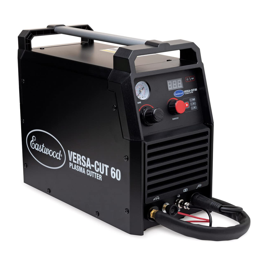
The EASTWOOD VERSA-CUT 60 PLASMA CUTTER is the best solution for making clean, fast cuts through steel, stainless or aluminum as thin as 24-gauge, or as thick as 7/8". Compared to mechanical cutting, the Versa-Cut 60 Plasma Cutter works significantly faster, and makes curved and intricate cuts more cleanly, easily and precisely. A built in pilot arc system allows for instant arc striking and ease of use when cutting rusty material and expanded metal. The internal moisture separator helps to deliver a clean, dry air supply to the torch, providing consistent results. Dual voltage capability allows the versatility to plasma cut with 120V household outlets and receptacles, or full 240V power when available.
READ AND UNDERSTAND ALL INSTRUCTIONS AND PRECAUTIONS BEFORE PROCEEDING.
This unit emits a powerful high voltage and extreme heat which can cause severe burns, electrical shock and death.
INCLUDES
COMPONENTS AND ACCESSORIES

(1) Versa-Cut 60 Plasma Cutter [A]
(1) 20 ft. Plasma Torch/Cable Assembly [B]
(1) 10 ft. Ground Cable/Clamp Assembly [C]
(1) Adapter Cord, 8" [0.2m] [D]
(1) Replacement Electrode [E]
(1) Replacement Nozzle [F]
(1) Torch Flow Tester [G]
(1) Electrode Wrench [H]
SPECIFICATIONS
| Power Voltage (V) | 1 phase, 120 VAC/240 VAC, 50/60 Hz |
| Maximum Output No Load Voltage (V) | 339V DC |
| Rated Input Current (Amps) | 120V: 39.4 Amps 240V: 44.5 Amps |
| Output Voltage | 120V: 88V - 92V 240V: 88V - 104V |
| Output Current Range (Amps) | 120V: 20 to 30 Amps 240V: 20 to 60 Amps |
| Duty Cycle (%) | 120V:60% @ 30 Amps - 100% @ 23 Amps 240V: 60% @ 60 Amps - 100% @ 46 Amps |
| Air Requirements | 5 - 7 CFM @ 20 - 60 PSI |
| Maximum Material Thickness | 120V: 3/16" 240V: 7/8" |
| Weight | 30.86 lbs. [14kg] |
| Dimensions | 17" x 8.5" x 14.7" [432mm x 215mm x 373mm] |
DUTY CYCLE
The rated Duty Cycle refers to the amount of plasma cutting that can be done within an amount of time. It is easiest to look at your plasma cutting time in blocks of 10 Minutes and the Duty Cycle being a percentage of that 10 Minutes. If plasma cutting at 60 Amps with a 60% Duty Cycle, within a 10 Minute block of time you can plasma cut for 6 Minutes with 4 Minutes of cooling for the Plasma Cutter.
If the Duty Cycle is exceeded, and the built-in Breaker is tripped, allow the unit to cool for a minimum of 15 minutes. When a safe temperature has been reached, the Plasma Cutter can be switched back on. To increase the duty cycle, turn down the Amperage Output control.
SAFETY INFORMATION
READ AND UNDERSTAND ALL INSTRUCTIONS AND PRECAUTIONS BEFORE PROCEEDING.
This unit emits powerful high current and extreme heat which can cause severe burns, dismemberment, electrical shock and death. Eastwood shall not be held liable for consequences due to deliberate or unintentional misuse of this product.

These instructions are intended only to provide the user with some familiarity of the Eastwood Versa-Cut 60. Electric arc cutting, interchangeably known as plasma cutting, is a highly complex procedure with many variables. If you have no prior experience with electric arc cutting, it is extremely important to seek the advice of someone experienced in electric arc cutting for instruction, enroll in a local technical school welding course or study a comprehensive how-to DVD and obtain a good quality reference book on electric arc cutting as there is a moderate learning curve necessary before achieving proficiency. Many welding practices, especially safety practices, transfer over to electric arc cutting directly. It is also strongly recommended that the user adhere to the American Welding Society guidelines, codes and applications prior to making cuts where safety is affected.
Plasma cutting can be dangerous to you and other persons in the work area. Read and understand this instruction manual before using this Eastwood plasma cutting machine. Injury or death can occur if safe plasma cutting practices are not followed. Safety information is set forth below and throughout this manual. Save these instructions for future reference.
To learn more about welding safety, read OSHA Title 29 CFR 1910, available at www.osha.gov; ANSI Z49.1, "Safety in Welding, Cutting and Allied Processes," available at www.aws.org; and the consumable manufacturer's Safety Data Sheets.

indicates a hazardous situation which, if not avoided, will result in death or serious injury.

indicates a hazardous situation which, if not avoided, could result in death or serious injury.

used with the safety alert symbol, indicates a hazardous situation which, if not avoided, could result in minor or moderate injury.

is used to address practices not related to personal injury.

ELECTRIC SHOCK CAN CAUSE INJURY OR DEATH!

- Improper use of a plasma cutter can cause electric shock, injury, and death! Read all precautions described in the plasma cutter manual to reduce the possibility of electric shock.
- Disconnect plasma cutter from power supply before assembly, disassembly, or maintenance of the torch, when installing or removing electrodes and nozzles.
- Always wear dry, protective clothing and leather welding gloves and insulated footwear. Use suitable clothing made from durable flame-resistant material to protect your skin.
- If other persons or pets are in the area of plasma cutting, use welding screens to protect bystanders from sparks.
- Always operate the plasma cutter in a clean, dry, well ventilated area. Do not operate the plasma cutter in humid, wet, rainy or poorly
- The electrode and work (or ground) circuits are electrically "hot" when the plasma cutter is on. Do not allow these "hot" parts to come in contact with your bare skin or wet clothing.
- Stay separated from the plasma cutting circuit by using insulating mats to prevent contact from the work surface.
- Be sure that the work piece is properly supported and grounded prior to beginning an electric plasma cutting operation.
- Always attach the Ground Clamp to the piece to be cut and as close to the plasma cutting area as possible. This will give the least resistance and best cut.
PLASMA CUTTING SPARKS CAN CAUSE FIRE OR EXPLOSION!

- Plasma cutting produces sparks which can be discharged considerable distances at high velocity igniting flammable or exploding vapors and materials.
- DO NOT operate the plasma cutter in areas where flammable or explosive vapors are present.
- DO NOT use near combustible surfaces. Remove all flammable items from the work area where plasma cutting sparks can reach (minimum of 35 feet).
- Always keep a fire extinguisher nearby while plasma cutting.
- Use welding blankets to protect painted and or flammable surfaces, rubber weather-stripping, dash boards, engines, etc.

ELECTROMAGNETIC FIELDS CAN BE A HEALTH HAZARD!

- The electromagnetic field that is generated during plasma cutting may interfere with various electrical and electronic devices such as cardiac pacemakers. Anyone using such devices should consult with their physician prior to performing any plasma cutting operations.
- Exposure to electromagnetic fields while plasma cutting may have other health effects which are not known.
ARC RAYS CAN INJURE EYES AND BURN!

- Arc rays produce intense ultraviolet radiation which can burn exposed skin and cause eye damage. Use a shield with the proper filter (a minimum of #11) to protect your eyes from sparks and the rays of the arc when plasma cutting or when observing the plasma arc cutting (see ANSI Z49.1 and Z87.1 for safety standards).
- Use suitable clothing made from durable flame-resistant material for skin protection.
- If other persons or pets are in the area of plasma cutting, use welding screens to protect bystanders from sparks and arc rays.
FUMES AND PLASMA CUTTING GASES CAN BE A HEALTH HAZARD!

- Fumes and gasses released during plasma cutting are hazardous. Do not breathe fumes that are produced by the plasma cutting operation.
- Prolonged inhalation of plasma cutting fumes above safety exposure limits can injure the lungs and other organs.
- Use enough ventilation and/or exhaust at the arc to keep fumes and gases from your breathing area.
- Use an OSHA approved respirator when plasma cutting in confined spaces or where there is inadequate ventilation.
- Use extreme caution when plasma cutting coated materials including but not limited to: cadmium plated, galvanized, lead based paints.
HOT METAL AND TOOLS WILL BURN!

- Plasma cutting heats metal and tools to temperatures that will cause severe burns!
- Use protective, heat resistant gloves and clothing when using Eastwood or any other plasma cutting equipment. Never touch a cut work surface, torch tip or nozzle until they have completely cooled.
FLYING METAL CHIPS CAN CAUSE INJURY!

- Grinding and sanding will eject metal chips, dust, debris, and sparks at high velocity. To prevent eye injury wear approved safety glasses.
- Wear an OSHA-approved respirator when grinding or sanding.
- Read all manuals included with specific grinders, sanders or other power tools used before and after the plasma cutting process. Be aware of all power tool safety warnings.

FIRST AID

- If exposed to excessive fumes move to an area with fresh air. Follow safety information on wire manufacturer's Safety Data Sheet.
- For other injuries follow basic first aid techniques and call physician or emergency medical personnel.
CONNECTING THE PLASMA CUTTER TO A POWER AND AIR SOURCE
The Eastwood Versa-Cut 60 Plasma Cutter requires a dedicated 240 VAC, 50 AMP, 50/60HZ grounded outlet protected by a circuit breaker. The plug installed on the plasma cutter is a NEMA 6-50P and should be used with a NEMA 6-50R receptacle.
As an alternative, by using the included Adapter Cord, the Versa-Cut 60 can be used with a 120 VAC, 20 AMP, 60HZ grounded NEMA 5-15R outlet protected by a circuit breaker.
Use only UL approved, 3 conductor grounded Extension cords. Use Eastwood #31739 for 120V operation and Eastwood #20029 or #20285 for 240V operation.
Plasma cutting also requires a pressurized air source. The air must be clean and dry and requires 5-7 CFM @ 60PSI. Usage of a moisture trap is strongly recommended. Air is connected via the rear panel mounted 1/4" Female NPT input.
CONTROL PANEL AND FEATURES
FRONT PANEL (FIG 1)

- Pressure Control: Pull out then turn knob to increase (+) or decrease (-) pressure. To lock, push in.
- Pressure Gauge: Adjust pressure control while air is flowing through the torch to get 60psi
- Amperage Control: (20A to 60A)
- Amperage Display: Shows the set plasma cutting amperage
- Plasma Cutting Mode Setting: Push button switches between TEST, 2T, and 4T modes
- Overload Indicator: Illuminates AMBER when the Duty Cycle has been exceeded, the plasma cutter is overloaded or if other abnormalities exist.
- Plasma Torch Air/Power Connection
- Pilot Arc Ignitor Connection
- Plasma Torch Trigger Connection
- Ground Clamp Connection
REAR PANEL (FIG 2)

aa. Power Cord
bb. Input Air Connection
cc. ON/OFF Switch
dd. Data Chart
VERSA-CUT 60 PLASMA CUTTER SET-UP
The Eastwood Versa-Cut is factory set-up for plasma cutting any material and thickness after the connections are attached.
INSTALLING THE GROUND CABLE AND CLAMP
- Locate the 10 ft. Ground Cable/Clamp Assembly [C] and connect the plug on the brass end to the Ground Clamp Connection on the Plasma Cutter [k]. Align the key of the brass ferrule with the notch of the receptacle at the 12:00 position, insert the plug and twist Clockwise 1/2 turn until it is tight (FIG 3).


CONNECTING AIR SUPPLY
- Place the Eastwood Versa-Cut 60 in a secure dedicated area or on a welding cart (not included).
- Install a quick connect 1/4" Male NPT fitting, or directly connect an air line with a 1/4" Male NPT fitting to the 1/4" Female NPT port at the rear of the plasma cutter [bb]. Usage of White Thread Sealing Tape, or similar, on this connection is recommended for a complete seal.
- Tighten the fitting with a wrench until snug, do not over tighten.
INSTALLING THE PLASMA CUTTING TORCH
- Thread the brass air/power fitting onto the connection at the front of the Plasma Cutter [g] and snug the connection with a wrench. White Thread Sealing Tape is not necessary as the connection utilizes an integral spherical sealing joint. Do not over tighten.
- Remove the thumb knob on the pilot arc ignitor connection [h] and install the pilot arc line ring terminal on the stud, reinstall the thumb knob.
- Install the plasma torch trigger connector to the connection point at the front of the Plasma Cutter [j] and thread the lock finger tight. All connections should now be installed as (FIG 3) shows.
OPERATING THE VERSA-CUT 60 PLASMA CUTTER
OVERLOAD PROTECTION
The Eastwood Versa-Cut 60 Plasma Cutter is equipped with an overload protection. This device will protect the Plasma Cutter if the duty cycle is exceeded. If the output is exceeded, the breaker will trip, the AMBER Overtemp Indicator will illuminate and cut off the power supply to the torch although the fan will still run to cool the unit. This protection circuit must be reset manually by switching the unit back ON. Before restarting the unit allow the Plasma Cutter to cool for a minimum of 15 minutes or until the AMBER Overtemp Indicator goes out.
AIR FLOW ADJUSTMENT
After connecting the air supply, the air flow rate needs to be adjusted so that the proper amount of air is flowing out through the torch.
- With the unit powered on and air supply connected, press the Plasma Cutting Mode Button[e] to cycle to TEST mode. Air should now be flowing through the torch.
- Pull the air pressure adjustment knob outward to unlock rotation, adjust pressure on the Pressure Gauge[b] to 60PSI.
- Push the adjustment knob back in to lock it. The air pressure is adjusted correctly.
PLASMA CUTTING MODES
The Eastwood Versa-Cut 60 Plasma Cutter has multiple trigger modes to select from utilizing the Plasma Cutting Mode Button [e]. Find the best mode for your project by reading the descriptions below.
- TEST - This mode is only utilized for testing air flow and making air pressure adjustments.
- 2T - As with 2T mode on a welder, it will activate plasma cutting for as long as the trigger is held. Good for short duration cuts in open areas.
- 4T - This mode requires one press of the trigger until the plasma cutting has started and the trigger can be released. To stop plasma cutting press the trigger again. 4T mode is helpful for long cuts that are fatiguing to hold the trigger for the entire duration, or a tight spot where you physically cannot hold the trigger down.
PLASMA CUTTING TECHNIQUE
- Start off learning plasma cutting on some scrap metal before moving on to a project or object of value. There is a moderate learning curve before achieving proficiency in plasma cutting.
- Place the Ground Cable Clamp on a clean, bare area of the workpiece. Scrape, wire brush, file or grind to bare metal if necessary to achieve a good ground.
- Verify the air pressure has been adjusted as described in Air Flow Adjustment.
- Adjust the output amperage to a suitable level for the material at hand; see the Versa-Cut 60 Plasma Cutter - Air Pressure and Amperage Settings chart following this section.
- Make sure all required safety gear is in place (Eye Protection, Welding Gloves, non-flammable long sleeve apparel) and the area is completely free of flammable material.
- To begin plasma cutting, depress the Torch Trigger to ignite the pilot arc. The tip of the torch must be touching or within a short distance to the work piece to begin the cut.
- The best results are achieved by holding the tip at a 90° angle to the cut line (FIG 4).

- The thicker the material, the longer it takes the plasma arc to fully penetrate. This is especially true when starting on the inside of a workpiece. While starting the arc hold the torch steady until it blows completely through, then continue the cut steadily, maintaining full penetration.
- Heavy plate is cleanest to start from an edge. The free space allows for the arc to steadily come into contact with the material and an easy route for the slag to be evacuated from the cut.
- With practice, you will be able to exercise precise control over this extremely powerful device, harnessing its energy to create clean, precise and intricate cuts in many forms of metal up to 7/8" thick.
- While practicing, experiment with different speeds. You will find that thinner materials will allow a faster motion while thicker materials will require a slower motion to achieve a through cut.
- A good form of practice is to attempt a series of straight lines while creating the cleanest edge possible with a minimum of molten material remaining on the cut edge. This minimizes the cleanup of the edge with a grinder or file. Another excellent technique is to practice plasma cutting your initials out of a piece of steel.

| Versa-Cut 60 Plasma Cutter - Air Pressure and Amperage Settings* | |||||||
| Metal Thickness | 1/32" | 1/16" | 3/32" | 1/8" | 5/32" | 3/16" | 7/32" |
| Amps | 20 | 20 | 20 | 20 | 20 | 20 | 30 |
| PSI | 60 | 60 | 60 | 60 | 60 | 60 | 60 |
| Metal Thickness | 1/4" | 9/32" | 5/16" | 11/32" | 3/8" | 13/32" | 7/16" |
| Amps | 30 | 30 | 40 | 40 | 40 | 50 | 50 |
| PSI | 60 | 60 | 60 | 60 | 60 | 60 | 60 |
| Metal Thickness | 15/32" | 1/2" | 17/32" | 9/16" | 19/32" | 5/8" | 21/32" |
| Amps | 50 | 50 | 50 | 50 | 50 | 50 | 50 |
| PSI | 60 | 60 | 60 | 60 | 60 | 60 | 60 |
| Metal Thickness | 11/16" | 23/32" | 3/4" | 25/32" | 13/16" | 27/32" | 7/8" |
| Amps | 50 | 50 | 50 | 60 | 60 | 60 | 60 |
| PSI | 60 | 60 | 60 | 60 | 60 | 60 | 60 |
*NOTE: These settings are base guidelines and may need to be adjusted based on individual techniques.
Do not Exceed 20 Amps when plugged into a 120V circuit.
CARE & MAINTENANCE
- It is extremely important that the air supply be clean and dry. A separate moisture trap, water/oil separator or desiccant system should be used.
- The Versa-Cut Plasma Cutter has an internal, built-in "last-chance" moisture separator with the outlet port located at the rear underside of the unit (FIG 5). This drains automatically whenever the compressed air source is removed.

- Constantly inspect the torch nozzle for excessive erosion, molten metal accumulation or burning. If damaged, it must be replaced.
- Before each use, inspect ALL electrical connections, cables, supply line, torch, air supply, housing and controls for damage. If any damage or wear is noted, DO NOT USE THE UNIT.
- Always store the unit in a safe, clean and dry environment.

TORCH MAINTENANCE
The Eastwood Versa-Cut 60 Plasma Cutter has several consumable parts that will need to be replaced over time. If wear or slag build up is noticed on any of the torch components, replace them immediately to avoid damage to the torch. Worn components will also contribute to poor plasma cutting and difficult arc starting.
See the torch components (FIG 6) exploded view for a reference of all the components and the assembly order.

TROUBLESHOOTING: OPERATIONAL PROBLEMS
| PROBLEM | CAUSE | CORRECTION |
| Plasma Cutter Will Not Power Up; GREEN Indicator Does Not Illuminate | Plasma Cutter not plugged into proper power supply | Check power supply. The VERSA-CUT 60 requires a properly grounded, 120 Volt AC, 20 Amp or 240 Volt AC, 50 Amp circuit. |
| Power supply breaker tripped | Reset breaker. | |
| Power switch not fully on | Check that Power Switch is fully "ON", GREEN indicator illuminates. | |
| Duty Cycle exceeded; Plasma Cutter overheated; AMBER indicator illuminated | Turn Power switch OFF, allow Plasma Cutter 15 minutes to cool then re-try. | |
| Plasma Cutter Shuts Off During Use While the Power Switch is On, AMBER Indicator Illuminated | Plasma Cutter Duty Cycle has been exceeded | Turn Power switch OFF, allow Plasma Cutter 15 minutes to cool then re-try. |
Water Drips from the Rear Underside of the Unit | The internal Moisture Trap is draining | No action required. This feature activates whenever the compressed air source is disconnected. |
TROUBLESHOOTING: CUTTING PROBLEMS
| PROBLEM | CAUSE | CORRECTION |
| Quality of Cut Has Degraded/Cut 60 is Underperforming | Improperly installed replacement consumables | Refer to Versa-Cut 60 Instruction Manual #58221Q for proper assembly of torch and consumables. |
| Worn or damaged consumables | Replace necessary consumables. NOTE: Always replace the Nozzle and Electrode together as a set. | |
| Poor panel connections on Versa-Cut 60 unit | Check that all fittings and connections for torch and ground clamp are fully attached to the Plasma Cutter unit. | |
| Poor ground connection on work piece | Check that the ground clamp is properly positioned, and a good ground is established on clean bare metal of work piece. | |
| Incorrect amperage or air pressure settings | Refer to Amperage and Air Pressure Settings chart in the #58221 Instruction Manual. | |
| Incorrect cutting speed | Slow down or speed up Torch movement speed as determined by the work piece material and thickness. | |
| The use of an undersized gauge and or too long of an extension cord causing an under-voltage condition | Use only UL approved, 3 conductor grounded Extension cords. Use Eastwood #31739 for 120V operation and Eastwood #20029 or #20285 for 240V operation. | |
| Supply air pressure too low to support plasma arc | Check air supply pressure. Do not attempt to operate the Versa-Cut below 60 PSI. | |
Inconsistent/ Fluctuating Arc | Improperly installed replacement consumables | Refer to Versa-Cut 60 Instruction Manual #58221Q for proper assembly of torch and consumables. |
| Worn or damaged consumables | Replace necessary consumables. NOTE: Always replace the Nozzle and Electrode together as a set. | |
| Poor panel connections on Versa-Cut 60 unit | Check that all fittings and connections for torch and ground clamp are fully attached to the Plasma Cutter unit. | |
| Poor ground connection on work piece | Check that the ground clamp is properly positioned, and a good ground is established on clean bare metal of work piece. | |
| Excessive moisture in the air supply | Install an effective moisture separator in the air supply to the Versa-Cut 60 unit. | |
| Refer to Versa-Cut 60 Instruction Manual #58221Q for proper procedure to drain the integral moisture separator inside the Versa-Cut 60 unit. | ||
| Supply air pressure too low to support plasma arc | Check air supply pressure. Do not attempt to operate the Versa-Cut below 60 PSI. | |
| Plasma Arc Blows Out, Easily Reignites on Successive Trigger Pulls | Torch being held too far from work piece | Hold torch closer to work piece, dragging the tip when possible. |
| Improperly installed replacement consumables | Refer to Versa-Cut 60 Instruction Manual #58221Q for proper assembly of torch and consumables. | |
| Worn or damaged consumables | Replace necessary consumables. NOTE: Always replace the Nozzle and Electrode together as a set. | |
| Air supply line to Versa-Cut 60 undersized | To provide adequate flow, an air supply line with a minimum of 3/8" I.D. is required. | |
| Supply air pressure too low to support plasma arc | Check air supply pressure. Do not attempt to operate the Versa-Cut below 60 PSI. | |
Arc Will not Transition from Pilot to Cutting Arc | Poor ground connection on work piece | Check that the ground clamp is properly positioned, and a good ground is established on clean bare metal of work piece. Remove any paint, rust, or other contaminants. |
| Worn out or damaged ground clamp | Replace or repair ground clamp. | |
| Torch being held too far from work piece | Hold torch closer to work piece, dragging the tip when possible. | |
| Supply air pressure too low to support plasma arc | Check air supply pressure. Do not attempt to operate the Versa-Cut below 60 PSI. | |
| Cut Will not Continue all the Way Through the Work Piece | Improperly installed replacement consumables | Refer to Versa-Cut 60 Instruction Manual #58221Q for proper assembly of torch and consumables. |
| Worn or damaged consumables | Replace necessary consumables. NOTE: Always replace the Nozzle and Electrode together as a set. | |
| Incorrect amperage or air pressure settings | Refer to Amperage and Air Pressure Settings chart displayed in the #58221 Instruction Manual. | |
| Incorrect cutting speed | Slow down or speed up Torch movement speed as determined by the work piece material and thickness. | |
| Poor panel connections on Versa-Cut 60 unit | Check that all fittings and connections for torch and ground clamp are fully attached to the Plasma Cutter unit. | |
| Poor ground connection on work piece | Check that the ground clamp is properly positioned, and a good ground is established on clean bare metal of work piece. | |
| Air supply line to Versa-Cut 60 undersized | To provide adequate flow, an air supply line with a minimum of 3/8" I.D. is required. | |
| Supply air pressure too low to support plasma arc | Check air supply pressure. Do not attempt to operate the Versa-Cut below 60 PSI. | |
| Material thickness exceeds 3/16" capability of the Versa-Cut 60 @ 120 Volts or 7/8" capacity @ 240 Volts | Do Not attempt to exceed the 3/16" thickness capability of the Versa-Cut 60 @ 120 Volts or 7/8" capacity @ 240 Volts. |
REPLACEMENT ITEMS
| #14343 | Plasma Cutter Torch Assembly, CB70 |
| #21543 | Trafimet Versa-Cut 60 Plasma Cutter Consumable Kit |
| #21553 | Plasma Cutter Nozzle CB50/70 1.0mm |
| #21554 | Plasma Cutter Nozzle CB50/70 0.8mm |
| #21555 | Plasma Cutter Air Diffuser CB50/70 |
| #21557 | Plasma 60 Electrode CB70 |
| #21558 | Plasma 60 Outer Nozzle CB70 |
ACCESSORIES
#13689 Plasma Cutting Guide
#12590 Welding Gloves – Large
#13848 Plasma Cutting Glasses
#20620 Eastwood Versa-Cut Plasma Cut 60 Cover
If you have any questions about the use of this product, please contact
The Eastwood Technical Assistance Service Department: 800.343.9353 >> email: tech@eastwood.com
PDF version of this manual is available at eastwood.com
The Eastwood Company
263 Shoemaker Road, Pottstown, PA 19464, USA
800.343.9353
eastwood.com
Documents / Resources
References
American Welding Society (AWS) - Welding Excellence Worldwide
Eastwood Auto Restoration Supplies - Eastwood Auto
Download manual
Here you can download full pdf version of manual, it may contain additional safety instructions, warranty information, FCC rules, etc.
Download Eastwood VERSA-CUT 60 (58221) - PLASMA CUTTER Manual
Advertisement
Thank you! Your question has been received!


Need Assistance?
Do you have a question about the VERSA-CUT 60 that isn't answered in the manual? Leave your question here.