Eastwood MP200i (65375) - AC/DC WELDER Manual
- Instructions manual (33 pages) ,
- Assembly and operating instructions manual (40 pages)
Advertisement
- 1 Introduction
- 2 CONTENTS
- 3 SPECIFICATIONS
- 4 SAFETY INFORMATION
- 5 ASSEMBLY
- 6 INSTALLING CABLE/HOSE HANGERS TO THE CABINET
- 7 CONTROL AND DISPLAY PANEL
- 8 INSTALLING THE MIG & TIG SHIELDING GAS SUPPLIES
- 9 MIG WELDING SET-UP
- 10 MIG WELDING OPERATION
- 11 MIG WELDING
- 12 MIG WELDING TECHNIQUES
- 13 TYPES OF WELD JOINTS
- 14 SPOOL GUN SET-UP AND OPERATION
- 15 SPOOL GUN WELDING
- 16 TIG WELDING SET-UP
- 17 TIG WELDING OPERATION
- 18 TIG WELDING
- 19 STICK WELDING SET-UP
- 20 STICK WELDING OPERATION
- 21 DC STICK MODE USER INTERFACE OPERATION
- 22 STICK WELDING
- 23 DATA CHART
- 24 TROUBLESHOOTING
- 25 MIG WELDING TROUBLESHOOTING
- 26 TIG WELDING TROUBLESHOOTING
- 27 STICK WELDING TROUBLESHOOTING
- 28 Documents / Resources
Introduction
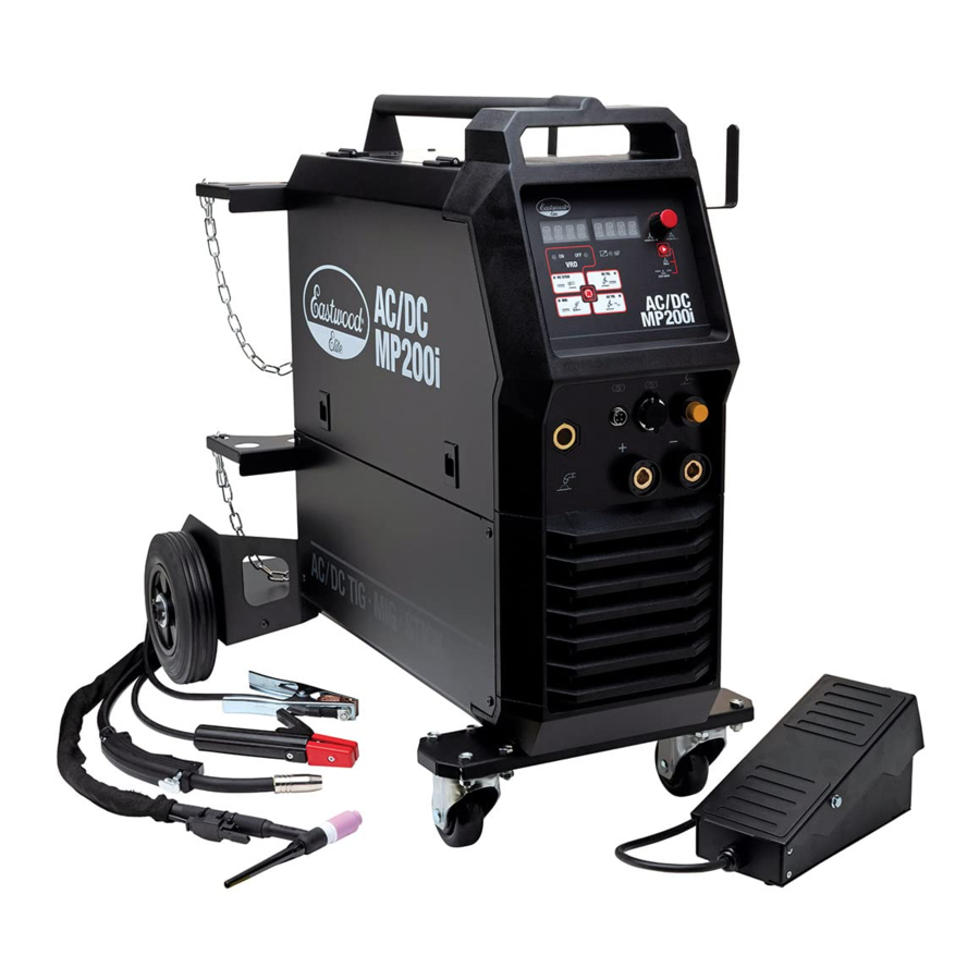
The EASTWOOD ELITE AC/DC MP200I provides no-compromise MIG, AC TIG, DC TIG, or ARC (Stick) welding operation all from a single, high-powered, spaceefficient unit that also serves as it's own heavy-duty Welding Cart! Your Eastwood Elite AC/DC MP200i Welder, with High Frequency Inverter Technology, is capable of welding thin or heavy gauge steel and aluminum with precision and ease. Designed with two complete and independent MIG and TIG gas systems, the Welder is prepared to seamlessly transition from quick MIG welding to precision TIG welding, and back again, all-the-while retaining your last settings. The TIG welding capability features advanced High Frequency Start Circuitry, selectable AC or DC welding output, pulse functionality, an included Foot Pedal and Flex Head TIG Welding Torch. Dual voltage means this unit can be used on a 120V household circuit or with 240V shop power.
READ AND UNDERSTAND ALL INSTRUCTIONS AND PRECAUTIONS BEFORE PROCEEDING.
This unit emits a powerful high voltage and extreme heat which can cause severe burns, electrical shock and death.
CONTENTS
COMPONENTS; BOX A

(1) Elite AC/DC MP200i Welder [A]
COMPONENTS; BOX B

(1) Rear Wheel/Gas Cylinder Tray Assembly [B]
(1) Front Caster Assembly [C]
(2) Gas Cylinder Brackets [D]
(2) Shielding Gas Hoses, 4.6' [1.4m] [E]
(1) Ground Clamp with 10' [3m] Cable [F]
(1) MIG Gun, with 8' [2.4m] Cable, 0.030" Contact Tip installed [G]
(1) Electrode Holder with 10' [3m] Cable [H]
(1) Flex Head TIG Welding Torch (WP-17F), with 12' [3.65m] Cable, 3/32" Gas Lens Collet Body, #8 "Gas Lens-Style" Gas Cup, 3/32" Collet, Long Back Cap, Collet Body Installed [J]
(1) Foot Pedal, 16' [4.85m] Cable [K]
(2) Cable/Hose Hangers [L]
(2) Gas Flowmeter (CO2/Argon) [M]
(1) Adapter Cord, 8" [0.2m] [N]
HARDWARE/ACCESSORIES; BOX B

(15) M5 x 12mm Screws [aa]
(3) M5 Nuts [bb]
(6) M5 Flat Washers [cc]
(3) M5 Lock Washers [dd]
(2) Gas Cylinder Chains, 36" [0.9m] [ee]
(1) 0.030" [0.8mm] MIG Gun Contact Tip [ff]
(1) 0.035" [0.9mm] MIG Gun Contact Tip [gg]
(1) MIG Contact Tip Wrench [hh]
(1) TIG Torch Collet, 1/16" [1.6mm] [jj]
(1) #8 TIG Torch "Gas Lens-Style" Gas Cup [kk]
(1) 1/16" TIG Torch Gas Lens Collet Body [mm]
(1) Tungsten 3/32" x 6" [2.4mm x 150mm], Red [nn]
SPECIFICATIONS
| Input Voltage | 240V±10% VAC, 50/60 Hz, 1 Phase | 120V±10% VAC, 50/60 Hz, 1 Phase |
| No Load Voltage | 68V | |
| Rated Input Current: MIG (I1max / I1eff) | 34.2A / 21.6A | 20.0A / 15.5A |
| Rated Input Current: TIG (I1max / I1eff) | 25.7A / 18.2A | 20.0A / 15.5A |
| Rated Input Current: STICK (I1max / I1eff) | 40.0A / 25.3A | 19.2A / 14.9A |
| Output Current Adjustment: MIG | 40A (16V) - 200A (24V) | 40A (16V) - 120A (20V) |
| Output Current Adjustment: TIG (DC) | 5A (10.2V) - 200A (18V) | 5A (10.2V) - 120A (14.8V) |
| Output Current Adjustment: TIG (AC) | 10A (10.4V) - 200A (18V) | 10A (10.4V) - 120A (14.8V) |
| Output Current Adjustment: STICK | 20A (20.8V) - 200A (28V) | 20A (20.8V) - 120A (24.8V) |
| Rated Duty Cycle: MIG | 40% @ 200A 60% @ 170A 100% @ 130A | - 60% @ 80A 100% @ 60A |
| Rated Duty Cycle: TIG | 50% @ 200A 60% @ 180A 100% @ 140A | - 60% @ 100A 100% @ 80A |
| Rated Duty Cycle: STICK | 40% @ 200A 60% @ 170A 100% @ 130A | - 60% @ 60A 100% @ 50A |
| Starting Method: TIG | Lift Start (DC Only) or High Frequency | |
| Power Factor | 0.73 | |
| Efficiency | 80% | |
| Wire Feed Speed: MIG | 39 - 590 in/min | |
| Post Flow Time: TIG | 0.0 - 30.0 s | |
| Welding Wire Diameter: MIG | 0.023" -0.035" | |
| Cooling | Dynamic Cooling Fan | |
| Overall Assembled Dimensions | 35.20" x 19.88" x 30.28" [894mm x 505mm x 769mm] | |
| Assembled Welder Weight | 95.68 lbs. [43.4kg] | |
| Welding Gas Cylinder Size Compatibility | 40 CF - 125 CF | |
| Maximum Overall Weight | 450 lbs. | |
DUTY CYCLE
The rated Duty cycle refers to the amount of welding that can be done within an amount of time. It is easiest to look at your welding time in blocks of 10 Minutes and the Duty Cycle being a percentage of that 10 Minutes. If welding at 170 Amps with a 60% Duty Cycle, within a 10 Minute block of time you can weld for 6 Minutes with 4 Minutes of cooling for the Welder.
If the Duty Cycle is exceeded, and the built-in Breaker is tripped, allow the unit to cool for a minimum of 15 minutes. When a safe temperature has been reached, the Welder can be switched back on. To increase the duty cycle, turn down the Voltage Output control. Going above 170 Amps will yield a lower Duty Cycle.
OVERLOAD PROTECTION
The Eastwood Elite AC/DC MP200i Welder is equipped with overload protection. This will protect the Welder if the duty cycle is exceeded. If the duty cycle is exceeded, the Welder will cut off the power supply to the Welder's outputs and the digital display will flash ERR -01- for overcurrent protection or ERR -02- for overheat protection. The fan will still run to cool the unit. For overcurrent protection, restart the machine and lower the outputs to prevent overloading again.
For overheat protection, allow the Welder to cool for a minimum of 15 minutes or until the error display goes out.
NOTE: The Eastwood Elite AC/DC MP200i is equipped with a dynamic cooling fan. The fan will NOT run when the unit is powered up. It will only run when required and it will turn off again when not needed. To verify function, switch the Welder off and the fan should run briefly.
SAFETY INFORMATION

These instructions are intended only to provide the user with some familiarity of the Eastwood Elite AC/DC MP200i.
Electric Welding is a highly complex procedure with many variables. If you have no prior experience with Electric Welding, it is extremely important to seek the advice of someone experienced in Electric Welding for instruction, enroll in a local technical school welding course or study a comprehensive how-to DVD and obtain a good quality reference book on Electric Welding as there is a moderate learning curve necessary before achieving proficiency in Welding different metals such as steel, stainless steel and aluminum. It is also strongly recommended that the user adhere to the American Welding Society guidelines, codes, and applications prior to producing welds where safety is affected.
Welding can be dangerous to you and other persons in the work area. Read and understand this instruction manual before using this Eastwood welding machine. Injury or death can occur if safe welding practices are not followed. Safety information is set forth below and throughout this manual. Save these instructions for future reference.
To learn more about welding safety, read OSHA Title 29 CFR 1910, available at www.osha.gov; ANSI Z49.1, "Safety in Welding, Cutting and Allied Processes," available at www.aws.org; and the consumable manufacturer's Safety Data Sheets.
The following explanations are displayed in this manual, on the labeling, and all other information provided with this product:

indicates a hazardous situation which, if not avoided, will result in death or serious injury.

indicates a hazardous situation which, if not avoided, could result in death or serious injury.

indicates a hazardous situation which, if not avoided, could result in minor or moderate injury.
 is used to address practices not related to personal injury.

ELECTRIC SHOCK CAN CAUSE INJURY OR DEATH!

- Improper use of an electric Welder can cause electric shock, injury, and death! Read all precautions described in the Welder Manual to reduce the possibility of electric shock.
- Disconnect Welder from power supply before performing any assembly, disassembly, or maintenance of the Welder.
- Always wear dry, protective clothing and leather welding gloves and insulated footwear. Use suitable clothing made from durable flame-resistant material to protect your skin.
- If other persons or pets are in the area of welding, use welding screens to protect bystanders from sparks.
- Always operate the Welder in a clean, dry, well-ventilated area. Do not operate the Welder in humid, wet, rainy, or poorly ventilated areas.
- The electrode and work (or ground) circuits are electrically "hot" when the Welder is on. Do not allow these "hot" parts to come in contact with bare skin or wet clothing.
- Separate yourself from the welding circuit by using insulating mats to prevent contact from the work surface.
- Be sure that the work piece is properly supported and grounded prior to beginning an electric welding operation.
- Always attach the Ground Clamp to the piece to be welded and as close to the weld area as possible. This will give the least resistance and best weld.
WELDING SPARKS CAN CAUSE FIRE OR EXPLOSION!

- Electric welding produces sparks which can be discharged considerable distances at high velocity igniting flammable or exploding vapors and materials.
- DO NOT operate electric arc Welder in areas where flammable or explosive vapors are present.
- DO NOT use near combustible surfaces. Remove all flammable items from the work area where welding sparks can reach (minimum of 35 feet).
- Always keep a fire extinguisher nearby while welding.
- Use welding blankets to protect painted and or flammable surfaces, rubber weather-stripping, dash boards, engines, etc.

ELECTROMAGNETIC FIELDS CAN BE A HEALTH HAZARD!

- The electromagnetic field that is generated during arc welding may interfere with various electrical and electronic devices such as cardiac pacemakers. Anyone using such devices should consult with their physician prior to performing any electric welding operations.
- Exposure to the electromagnetic fields generated while welding may have other health effects which are not known.
ARC RAYS CAN INJURE EYES AND BURN!

- Arc rays produce intense ultraviolet radiation which can burn exposed skin and cause eye damage. Use a shield with the proper filter a minimum of #11) to protect your eyes from sparks and the rays of the arc when welding or when observing open arc welding (see ANSI Z49.1 and Z87.1 for safety standards).
- Use suitable clothing (long pants, long sleeves, closed toe shoes, gloves) made from durable flame-resistant material for skin protection.
- If other persons or pets are in the area of welding, use welding screens to protect bystanders from sparks and arc rays.
FUMES AND WELDING GASES CAN BE A HEALTH HAZARD!

- Fumes and gasses released during welding are hazardous. Do not breathe fumes that are produced by the welding operation.
- Prolonged inhalation of welding fumes above safety exposure limits can injure the lungs and other organs.
- Use enough ventilation and/or exhaust at the arc to keep fumes and gases from your breathing area.
- Use an OSHA approved respirator when welding in confined spaces or where there is inadequate ventilation.
- Never weld coated materials including but not limited to: cadmium plated, galvanized, lead based paints, powder coat.
BUILDUP OF GAS CAN INJURE OR KILL!

- Shut off gas supply when not in use.
- Ensure adequate ventilation of the welding area.
- Do not weld in confined areas.
- Always turn your face away from valve outlet when opening cylinder valve.
CYLINDERS CAN EXPLODE IF DAMAGED!

- Shielding gas cylinders contain gas under high pressure. If damaged, a cylinder can explode. As gas cylinders are a normal component of the welding process, use extra care to handle them carefully.
- Protect compressed gas cylinders from excessive heat, mechanical shocks, physical damage, slag, open flames, sparks, and arcs. Keep away from any welding or other electrical circuits.
- Install cylinders in an upright position by securing to a specifically designed rack, cart, or stationary support to prevent falling or tipping over.
- Never weld on a pressurized cylinder or explosion will occur.
- Use only correct shielding gas cylinders, regulators, hoses, and fittings designed for the specific application; maintain them and all related components in good condition.
- Keep protective cap in place over valve except when cylinder is in use.
- Use proper equipment, procedures and have adequate help when moving or lifting cylinders.
HOT METAL AND TOOLS WILL BURN!!

- Electric welding heats metal and tools to temperatures that will cause severe burns!
- Use protective, heat resistant gloves and clothing when using Eastwood or any other welding equipment. Never touch welded work surface, the welding torch tip, nozzle or tungsten until they have completely cooled.
FLYING METAL CHIPS CAN CAUSE INJURY!

- Grinding and sanding will eject metal chips, dust, debris, and sparks at high velocity. To prevent eye injury wear approved safety glasses.
- Wear an OSHA-approved respirator when grinding or sanding.
- Read all manuals included with specific grinders, sanders or other power tools used before and after the welding process. Be aware of all power tool safety warnings.
INJURY HAZARD!

- Pull and guide Welder by the top Handle only.DO NOT pull on welder cables, hoses or wires to move Welder.
- Use caution not to trip on welder cables, hoses or wires when in use for welding.
- The Welder is intended for use with up to two 7" diameter cylinders. Use caution when handling compressed gas cylinders and always keep in the upright position.
- ALWAYS properly secure welding gas cylinders in place with the supplied chains.
- This Welder is designed to accommodate specified welding gas cylinders only.
- DO NOT lift the Welder by the top Handle. Doing so may result in failure of the Handle mounting points which can allow the Welder to fall causing severe injury!
- DO NOT exceed the rated 450 lbs. [205kg] weight capacity.
- DO NOT use as a seat.
- DO NOT stand or step on the Welder.
- Use on a flat and level surface only.DO NOT use on sloped surfaces.
DO NOT LIFT WELDER WITH CYLINDERS INSTALLED!
- Lifting the Welder by the top handle with welding gas cylinders installed could result in failure at the mounting points and the Welder dropping. If the Welder needs to be lifted by the handle, remove the gas cylinders first.
FIRST AID

- If exposed to excessive fumes move to an area with fresh air. Follow safety information on the welding wire, tungsten electrode, filler rod and stick electrode manufacturers' Safety Data Sheets.
- For other injuries follow basic first aid techniques and call physician or emergency medical personnel.
CONNECTING THE WELDER TO A POWER SOURCE
The Eastwood Elite AC/DC MP200i Welder requires a dedicated 240 VAC, 50 AMP, circuit breaker protected outlet. The plug installed on the Welder is a NEMA 6-50P and should be used with a NEMA 6-50R receptacle. If unsure about your electrical setup contact a licensed electrician.
As an alternative, by using the included Adapter Cord, the AC/DC MP200i can be used with a dedicated 120 VAC, 20 AMP grounded NEMA 5-15R outlet protected by a circuit breaker.
If using an extension cord is required, we recommend using our Welder Extension Cords for optimal performance: Eastwood items #31739 25ft Heavy Duty 110V Extension Cord, #20029 25ft Heavy Duty 220V Extension Cord, and #20285 40ft Heavy Duty 220V Extension Cord.
ASSEMBLY
FRONT WHEELS
- Pull Welder [A] from packaging, lift front end and support it securely.
- Using three M5 Nuts [bb] and Washers [cc], attach the Front Caster Assembly [C] to the underside of the cabinet (FIG 1).


REAR WHEELS
- Lift and support the rear end of Welder [A].
- Use nine M5 x 12 Screws [aa] and Washers [cc]; five at the underside (FIG 2), four at the rear (FIG 3) to attach the Rear Wheel/Tray Assembly [C] to the underside and rear of the cabinet.


GAS CYLINDER BRACKETS
- With flanges facing downward, attach the two Gas Cylinder Brackets [D] to the rear of the cabinet with three M5 x 12 mm Screws [aa] for each support (FIG 4).


INSTALLING CABLE/HOSE HANGERS TO THE CABINET
Two included Cable/Hose Hangers [L] are optional and may be added to the cabinet if desired. To do so:
- Remove four existing M5 screws from the upper right side of the Welder Cabinet [A] and set aside for re-use.
- Locate the Cable/Hose Hangers [L] with the offset up and outward and secure with the previously removed M5 Screws (FIG 5). NOTE: Upper Front Screw is longer.


CONTROL AND DISPLAY PANEL
FRONT UPPER PANEL (FIG 6)

- Digital Displays. The dual digital displays are your visual interface with the machine. They show all welding parameters, menus, and settings.
- Adjustment Knob. Rotate Knob clockwise and counterclockwise to fine-adjust parameters up and down, respectively. Press Knob and rotate to make coarse adjustments. This is particularly helpful when making a large change in settings.
- Menu Button. Pressing the menu button will allow the Knob to change alternate parameters. Long presses, meaning the press is held for approximately three seconds, will open the user menu where in-depth process specific changes can be made.
- Foot Pedal Indicator. Illuminates when the Foot Pedal is connected in TIG mode.
- VRD Indicator. Shows whether the Voltage Reducing Device (VRD) is turned on or off for Stick Welding.
- Mode Selection Button. The Mode Selector Button cycles the Welding Mode you are in. Current Mode is shown by the illuminated LED in the Mode's box.
FRONT LOWER PANEL (FIG 7)

- MIG Gun Power/Gas/Wire Feed Socket
- MIG Gun Trigger Wire Connection
- TIG Torch Power/Gas Connection
- TIG Trigger and Foot Pedal Connection
- Positive Connection
- Negative Connection
REAR PANEL (FIG 8)

- Power Cord
- ON/OFF Switch
- MIG Shielding Gas Connection
- TIG Shielding Gas Connection
INSTALLING THE MIG & TIG SHIELDING GAS SUPPLIES
NOTE: The following steps cover the installation of the Shielding Gas Valves, Hoses and Tanks (not included). For flow adjustment, see MIG SHIELDING GAS FLOW ADJUSTMENT and TIG SHIELDING GAS FLOW ADJUSTMENT.
BUILDUP OF GAS CAN INJURE OR KILL!
- Shut off shielding gas supply when not in use.
- Always ventilate confined spaces or use approved air-supplied respirator.
- Always turn your face away from valve outlet when opening cylinder valve.
CYLINDERS CAN EXPLODE IF DAMAGED!
Shielding gas cylinders contain gas under high pressure. If damaged, a cylinder can explode. As gas cylinders are a normal component of the welding process, use extra care to handle them carefully.
- Protect compressed gas cylinders from excessive heat, mechanical shocks, physical damage, slag, open flames, sparks, and arcs. Keep away from any welding or other electrical circuits.
- Install cylinders in an upright position by securing to a specifically designed rack, cart, or stationary support to prevent falling or tipping over.
- Never weld on a pressurized cylinder or explosion will occur.
- Use only correct shielding gas cylinders, regulators, hoses, and fittings designed for the specific application; maintain them and all related components in good condition.
- Keep protective cap in place over valve except when cylinder is in use.
- Use proper equipment, procedures and have adequate help when moving or lifting cylinders.
UNSECURED BOTTLES CAN INJURE!
- The integral bottle rack on the Eastwood Elite AC/DC MP200i is not capable of securing welding gas bottles larger than 125CF. If a larger bottle is being used it must be secured separately. Use proper equipment, procedures and have adequate help when moving or lifting cylinders.
Shielding Gas Bottles are NOT INCLUDED with the Eastwood Elite AC/DC MP200i but are necessary to MIG and TIG welding. They can be bought at most local Welding Supply Stores. The Eastwood Elite AC/DC MP200i is capable of securing up to two 40CF - 125CF welding gas cylinders. Eastwood recommends the use of 75% Argon / 25% CO2 when MIG welding steel, 100% Argon for Aluminum, and Tri-Mix (90% He / 7.5% Ar / 2.5% CO2) for Stainless Steel. 100% Argon is recommended for all TIG welding applications.

- Place the Shielding Gas Tanks on the Rear Tray [B] of the MP200i and mount them securely with the included Gas Cylinder Chains [ee].
- Remove the caps from the Shielding Gas Bottles.
- Insert the large male fitting on the Gas Flowmeters (CO2/Argon) [M] into the female fittings on the Shielding Gas Bottles (not included).
![]()
Do not use White Thread Sealing Tape on these connections as it is an inert spherical gas fitting and does not require it. If you have a leak check for burrs or dirt in the threads or on the spherical joints. - Tighten the fittings with a wrench until snug, do not over tighten(FIG 9).
- Connect either end of the Shielding Gas Hoses [E] included with the Eastwood Elite AC/DC MP200i to the fitting on the Regulators and wrench tighten until snug (FIG 9).
- Connect the other end of the gas lines to the appropriate MIG and TIG fittings on the rear of the Eastwood Elite AC/DC MP200i and wrench tighten until snug (FIG 8).
- Check the gas lines for leaks by slowly opening the valves on the gas bottles. When welding the valves on the bottles should always be fully open. Close them when done welding to avoid loss of gas.
MIG WELDING SET-UP
ELECTRIC SHOCK CAN CAUSE INJURY OR DEATH!
Turn the ON/OFF Switch [h] on the Rear Panel to the OFF position and unplug the Welder from the power supply before beginning welder set-up.
INSTALLING THE MIG GUN
- Open the Side Panel Door of the Welder and loosen the MIG Gun Thumb Screw (FIG 10).

- Slide the brass body of the MIG Gun in through the front of the Welder into the MIG Gun Power/Gas/Wire Feed Socket [a]. Be sure to insert it until it bottoms out against the drive assembly or a gas leak may occur.
NOTE: If insertion is difficult, lubricate the O-rings with a silicon based lubricant or dish soap. - Tighten the MIG Gun Thumb Screw.
- Connect the metal Trigger Plug to the MIG Gun Trigger Wire Connection [b] at the Front Upper Panel.

INSTALLING THE GROUND CABLE AND CLAMP FOR SOLID WIRE MIG (DCEP) WELDING WITH SHIELDING GAS
- Locate the Ground Clamp with Cable and connect the plug on the cable end to the( - ) Negative Connection [f] at the Front Lower Panel of the Welder. To connect the plug, line up the key on the plug with the keyway on the socket of the Welder, insert the plug and twist clockwise until it is tight (FIG MIG).

- The Welder must also be set to MIG mode by pressing the MODE SELECTION BUTTON [6] and configured for solid wire welding. This is detailed further in MIG MODE USER INTERFACE OPERATION.

CHANGING THE POLARITY FOR FLUX-CORED MIG (DCEN) WELDING
- Setup the Welder as described above. The Welder will automatically swap polarity when set to FLUX mode. This is detailed further in MIG MODE USER INTERFACE OPERATION.
DRIVE ROLLER
The Eastwood Elite AC/DC MP200i is designed to use 0.023" to 0.035" wire and is equipped with a Dual-Groove Drive Roller. As assembled, it will accept 0.030"/0.035" [0.8mm/0.9mm] wire. To use 0.023" [0.6mm] wire, it must be reversed. To do so:
- Unthread the Drive Roller Thumbscrew (FIG 10).
- Pull the Drive Roller from the shaft.
- The indicated wires sizes are stamped on the face of the Drive Roller.
- Choose the wire size needed and slip the Drive Roller back onto the shaft with the desired wire size stamping facing inward (FIG 11).

- Replace Drive Roller Thumbscrew.

INSTALLING THE WIRE SPOOL
The Eastwood Elite AC/DC MP200i can be used with either a 4" or an 8" wire spool. A 4" Spool fits directly on the Spool Shaft and the included, pre-installed 8" Spool Adapter must be removed and placed in a safe location for future use.
To use the larger 8" spool, the included, pre-installed 8" Spool Adaptor must be used.
TO INSTALL A 4" WIRE SPOOL:
- Open the Side Panel Door of the Welder and remove the Spool Retaining Wingnut, Spacer, and 8" Spool Adaptor from the Wire Spool Spindle (FIG 12).

- With the wire feedoriented forward and from the underside of the spool, slide the 4" Wire Spool onto the Spindle and reinstall the Spacer and the Spool Retaining Wingnut (FIG 13). Then place the 8" Spool Adaptor in a safe place. DO NOT unravel wire at this point.


SETTING THE WIRE TENSION ADJUSTER
- To set the tension on the wire, incrementally tighten the Spool Retaining Wingnut at the center of the Spindle until there is a slight resistance to spinning the wire spool on the Spindle. If the tension is set too loose the wire spool will freely spin on the shaft and unspool all the wire. If the tension is too tight, the Drive Roller will have difficulty pulling the wire off the spool and some slipping may occur.
TO INSTALL AN 8" WIRE SPOOL:
- Open the Side Panel Door of the Welder and remove the Spool Retaining Wingnut and Spacer from the Wire Spool Spindle.
- Slide the included 8" Wire Spool Adaptor into the center of the Wire Spool.
- Reinstall the Spacer and the Spool Retaining Wingnut.
- With the wire feeding forward from the underside of the spool, slip the Wire Spool onto the 8" Wire Spool Adaptor. When doing so, be sure the Drive Pin of the Adapter is engaged with a spoke of the Spool.
- Set tension on the wire as noted in above steps.
THREADING WIRE THROUGH THE DRIVE MOTOR TO THE MIG GUN
This Welder uses wire sizes ranging from 0.023" to 0.035" [0.6mm to 0.9mm]. To install welding wire, follow the procedure outlined below:
ELECTRIC SHOCK CAN CAUSE INJURY OR DEATH!
This procedure requires that the Welder power be switched on. DO NOT make contact with the wire when the MIG Gun Trigger is depressed.

- Turn the ON/OFF Switch [h] on the Rear Panel to the OFF position and unplug the Welder from the power supply.
- Unthread the Nozzle and using the included Contact Tip Wrench [hh] remove the Contact Tip from the end of the MIG Gun.
- Make sure that the Drive Roller is installed in the proper position in accordance with the wire size being used, as described in the DRIVE ROLLER section of these instructions.
- Flip the Wire Tensioner outward, pivot it down and out of the way, then pivot the Tension Arm up away from the Drive Roller (FIG 14).

- Pull out welding wire from the wire spool carefully.
![]()
DO NOT let go of the wire or the entire spool could unravel. - Cut off the small piece of the curved segment at the front of the welding wire and straighten the welding wire approximately 3" long.
- Thread the welding wire feeding from the underside of the spool and forward through the Guide Tube then over the wire Drive Roller and into the Wire Feed Hole (FIG 15).
- Replace the Tension Arm and re-latch the Wire Tensioner back into place (FIG 15).
- Connect the Welder to a power supply and turn the ON/OFF Switch [h] on the Rear Panel to the ON position. Set the process via the Mode Selection Button on the Front Upper Panel to MIG.
- With the gun pointed away from you and others, depress the trigger to begin feeding wire. After approximately 5 seconds the drive motor will go into quick feed mode.
NOTE: The Wire Tensioner may need to be set. To do so:- Watch the Drive Roller to see if any slipping is occurring between the roller and the wire. If so; turn the machine off, unplug it and tighten the Pressure Adjusters 1/4 turn and test again.
- Repeat the above step until wire is feeding smoothly with no binding or slippage.
- Once the wire exits the end of the gun, turn the ON/OFF Switch [h] on the Rear Panel to the OFF position and unplug the Welder from the power supply.
- Reinstall the Contact Tip and Nozzle. Cut the wire about 1/4" from the end of the Contact Tip.

MIG WELDING OPERATION
MIG MODE USER INTERFACE OPERATION
The Eastwood Elite AC/DC MP200i has several configurable and preset options to help you succeed in welding. The adjustments available in MIG mode are detailed below.
DEFAULT VIEW
The default view in MIG mode (FIG 16) shows the Welder's set voltage and wire speed in inches per minute. Rotate the Adjustment Knob to fine-adjust parameters. Press the knob and rotate to make coarse adjustments.

- WIRE SPEED: Rotating the Adjustment Knob will adjust the wire speed. The number will blink while being adjusted.
- Voltage: Pressing the Menu Button switch to voltage adjustment. The number will blink while being adjusted. Press the Menu Button again to switch back to wire speed.
USER MENU
Long pressing the Menu Button (holding it for three seconds) will open the User Menu where the below settings can be adjusted. Pressing the Menu Button will cycle through them and scrolling the Adjustment Knob will change them. To save and exit automatically, do not adjust anything for five seconds and it will return to the default view.
- PROCESS: The first option shown is the process selection. Here you can select:
- C25: Standard mode for solid wire MIG welding with a 75% Argon / 25% CO2 gas mixture.
- C100: Alternate solid wire welding profile for use with 100% CO2 gas MIG welding. It is designed to compensate for the hotter welding with this gas.
- FLUX: For gasless welding utilizing flux-cored wire. Automatically swaps polarity to DCEN.
- ALUM: Spool Gun mode for MIG welding aluminum with a #20172 Spool Gun.
- WIRE DIAM: Select the wire diameter, in inches, you are utilizing.
- INDU: The inductance setting controls the rate of current rise following the short-circuit state, that is, during the time when the wire is short circuiting into the weld puddle. This setting affects arc time too, that is, the amount of time the short circuit cycle spends arcing and providing heat to the puddle. Higher inductance settings increase the time of each individual arc cycle and therefore can improve the wetting of a puddle. This produces a "softer" puddle which is excellent for smooth fillet welds. Lower inductance settings increase the frequency of each short circuit/arc cycle and can be useful for pinpointing a narrow bead in some joints. It offers greater penetration; however, it will produce more spatter.
- FACT DFLT: Setting to YES and pressing the Mode Selection Button to confirm will return settings to factory defaults. These defaults will take the Welder back to good weld settings for 1/8" material. Factory default settings are:
- Voltage: 19.0V
- Wire Speed: 280 IPM
- Process: C25
- Wire Diameter: 0.030"
- Inductance: 0%
MIG SHIELDING GAS FLOW ADJUSTMENT
After connecting the Shielding Gas Regulator, the gas flow rate needs to be adjusted so that the proper amount of Shielding Gas is flowing over the weld. If there is too little gas flow, there will be porosity in the resulting welds as well as excessive spatter.
If there is too much gas flow, this will be wasting gas and may affect the weld quality. The included Regulator has 2 gauges on it; the gauge on the left is Flow Rate while the gauge on the right is Tank Pressure.
ELECTRIC SHOCK CAN CAUSE INJURY OR DEATH!
This procedure requires that the Welder power be switched on. DO NOT make contact with the wire when the MIG Gun Trigger is depressed.
- Open the MIG Shielding Gas tank valve all the way.
- Adjust the knob on the Pressure Regulator to ~30 CFH.
- After the Welder is turned on and set to MIG mode, the Trigger of the MIG Gun (or Spool Gun) will control the internal gas flow.
- As the MIG Gun is triggered, the Gas Flow needle will drop to a steady reading. This is the value to be used for measuring Gas Flow.
- The Gas Flow should ideally be set to ~20 CFH while flowing. The CFH (Cubic Feet per Hour) scale is the inside scale in red on the Flow Gauge. 20 CFH is the most typical flow rate but it may need to be adjusted in some cases depending on if there is a slight breeze or some other instance where additional shielding gas is required to prevent porosity in the weld.
- When finished welding, the Valve on the Gas Bottle must be closed.
MIG WELDING
ELECTRIC SHOCK CAN CAUSE INJURY OR DEATH!
- Improper use of an electric Welder can cause electric shock, injury and death! Read all precautions described in the Welder Manual to reduce the possibility of electric shock.
- Disconnect Welder from power supply before assembly, disassembly or maintenance of the MIG Gun, Contact Tip and when installing or removing Nozzles.
- Always wear dry, protective clothing and leather welding gloves and insulated footwear. Use suitable clothing made from durable flame-resistant material to protect your skin.
- Always operate the Welder in a clean, dry, well ventilated area. Do not operate the Welder in humid, wet, rainy or poorly ventilated areas.
- The electrode and work (or ground) circuits are electrically "hot" when the Welder is on. Do not allow these "hot" parts to come in contact with bare skin or wet clothing.
- Separate yourself from the welding circuit by using insulating mats to prevent contact from the work surface.
- Be sure that the work piece is properly supported and grounded prior to beginning an electric welding operation.
The Eastwood Elite AC/DC MP200i can be used to form a large number of different joints and welds all of which will require practice and testing before using on an actual project piece. This following welding process is just a baseline to get you started. Welding, as with any skill, requires a learning curve to achieve proficiency. An extended period of "Trial and Error" performed on scrap material is required before welding on an actual project can begin.
This machine has smart wire feeding technology to prevent forcing excessive wire into the start of the weld. When the machine is not welding and feeding wire, it will feed wire at a slow fixed speed for approximately five seconds, and then speed up to max speed. This is to quickly feed wire through the torch. Once the machine senses that it is welding it will automatically run at the preset wire speed that the user has set on the machine. Do not be alarmed when the wire feeds slowly while not welding.
- Refer to the Suggested Settings Chart which is located on the inside of the Side Panel Door of the Eastwood Welder. It is also located towards the end of this manual, see DATA CHART (FIG 26). From the chart select the baseline starting point for the recommended settings described in the chart.
- Connect your ground clamp to the workpieces that are to be welded. Make sure the ground clamp contacts are placed on a clean piece of metal free of paint, grease, rust, oils, etc. It is recommended to place your ground clamp as close to the welding area as possible.
- Assess the general work area and make sure the welding area is also cleaned of any paint, grease, rust, oils, etc.
- Plug in the Welder and move switch to the ON position.
- The Welder must be set to MIG mode by pressing the Mode Selection Button [6] and configured for the type of welding you are performing. This is detailed further in MIG MODE USER INTERFACE OPERATION.
- Depress the MIG Gun trigger pointing the gun away from your body and then let go of the trigger and cut the wire back to ~1/4" stick out length.
- Wearing your welding helmet, gloves, and long sleeve shirt and pants, put the end of the wire sticking out of the gun into the joint to be welded.
- Position the MIG Gun so that it is perpendicular to the base metal with ~20° tilt back.
- Depress the trigger to start the wire feed which starts the arc.
NOTE: A push, perpendicular, or drag technique can be used to weld the pieces together; the type used depends on the type of joint as well as other influential conditions.- Once you depress the trigger and the arc has started, you will notice a molten puddle forming; this puddle is the weld bead and will follow the motion of the MIG Gun.
- Watching the size of the puddle dictates how fast you should be moving with the gun.
- If you burn through the material, you are either moving too slow or you need to adjust the Welder settings such as decreasing wire speed and voltage, for example.
- If you're not penetrating the base metal, you're either moving too fast or you need to adjust the Welder settings such as increasing wire speed and voltage, for example.
- Release the trigger on the MIG Gun to stop the weld.
- After welding is complete, turn off the Welder and disconnect from the power source.
MIG WELDING TECHNIQUES
SHEET METAL WELDING TECHNIQUES
When welding sheet metal a different approach is usually taken to account for how thin the metal is and how susceptible to warping it is. The technique most often used is called Stitch Welding and this process is described below:
- Clean the metal to be welded of any paint, rust, oil, grease, dirt, or any other contaminants that may be on the surface of the piece.
- Secure the pieces to be welded in place using clamps. Be sure to leave a small gap between the two pieces of sheet metal for the weld to flow into, this will result in a lower bead height which will require minimal finishing.
- Consult the Suggested Settings Chart and set the Voltage and Wire Speed appropriately.
- Get some pieces of scrap metal of the same thickness and verify that the settings will work for the specific weld you will be making.
- Once the settings have been fine-tuned tack weld your final pieces in places and remove the clamps if they are in the way of the weld.
- The Stitch Welding technique can now be utilized which is basically a series of connected "Tacks" To perform the technique, depress the trigger for a short period of approximately half a second to lay a tack. Continue to trigger the gun on and off, making a series of connected tack welds following along the path of the weld joint. Continue the series of tacks for an inch or so and then move to a different section of the weld and perform the process there. It is essential to keep moving around to spread out the heat making sure not to get one section too hot, warping the metal.
- Once the entire weld has been completed allow the metal to cool. If necessary, follow up with a flap disc to grind the weld bead flush.
HEAVIER GAUGE METAL WELDING TECHNIQUES
DO NOT attempt to weld material thicker than 3/8".
When welding heavier gauge metal, a continuous bead is formed using a 'push' method. This process is described below:
- Clean the metal to be welded of any paint, rust, oil, grease, dirt or any other contaminants that may be on the surface of the piece.
- Secure the pieces to be welded in place using clamps. Be sure to leave a small gap between the two pieces of metal for the weld to flow into, this will result in a lower bead height which will require minimal finishing.
- Consult the Suggested Settings Chart on the inside of the Side Panel Door and set the Voltage and Wire Speed appropriately.
- Get some pieces of scrap metal of the same thickness and verify that the settings will work for the specific weld you will be making.
- Once the settings have been fine-tuned, tack weld the final pieces in place and remove the clamps if they are in the way of the weld.
- When welding heavy gauge metal there are two basic approaches to creating the weld. The first is a continuous bead with steady gun movement along the length of the joint. The second type of weld is a Stringer or Weave bead. This is accomplished by moving the MIG Gun in a circular or zig zag pattern. Either of these techniques will create strong welds but in some cases the Stringer or Weave type will create a more aesthetically pleasing weld bead.
- Once the entire weld has been completed, allow the metal to cool. If necessary, follow up with a flap disc to grind the weld bead flush.
TYPES OF WELD JOINTS
BUTT WELD is a joint between two pieces that are laying in the same direction.

EDGE WELD is a joint between two pieces where the edges re being joined.

TEE WELD is a joint between two pieces where one is perpendicular to the other.

CORNER WELD is a joint between two pieces that meet at or near perpendicular at their edges.

LAP WELD is a joint between two overlapping pieces.

PLUG WELD is a joint which joins two overlapping pieces by filling in a hole punched in the top piece.

SPOOL GUN SET-UP AND OPERATION
(Spool Gun Available Separately, not included)
ELECTRIC SHOCK CAN CAUSE INJURY OR DEATH!
Turn the ON/OFF Switch [h] on the Rear Panel to the OFF position and unplug the Welder from the power supply before beginning welder set-up.
SET-UP FOR SPOOL GUN WELDING
The Eastwood Elite AC/DC MP200i is designed to accept an Eastwood #20172 Spool Gun (available separately, not included) which allows for easy feeding of aluminum wire to expand the AC/DC MP200i MIG welding capabilities. This is an optional accessory and can be purchased separately from Eastwood. A cylinder of 100% Argon Gas (not included) from a local welding supplier is also required.
INSTALLING THE SPOOL GUN
SHOCK HAZARD!
Turn Off Welder and unplug from power source before installing or removing the Spool Gun or MIG Gun.
- Open the Side Panel Door of the Welder and cut the MIG Wire from the Spool.
NOTE: DO NOT allow the Spool of wire to unravel. - Flip the Wire Tensioner outward, pivot it down and out of the way to release wire tension. Pull the remainder of the cut MIG wire from the MIG Gun Nozzle. Return the Wire Tensioner to the locked position.
- Loosen the MIG Gun Thumb Screw and remove the MIG Gun from the MIG Gun Power/Gas/Wire Feed Socket [a].
- Install the Brass Body End of the Spool Gun Cable Assembly into the socket and tighten the MIG Gun Thumb Screw.
![]()
The Brass Body End of the Spool Gun Hose/Wire Cable MUST BE fully seated against the base of the drive assembly socket or gas may either leak or not be able to pass through the connection to the end of the Spool Gun. - Remove the MIG Gun Trigger plug and install the Spool Gun Trigger Plug to the MIG Gun Trigger Wire Connection [b] at the Front Upper Panel.
INSTALLING THE GROUND CABLE AND CLAMP
- The Ground Cable Clamp installation is the same as for the MIG Gun, see INSTALLING THE GROUND CABLE AND CLAMP FOR SOLID WIRE MIG (DCEP) WELDING WITH SHIELDING GAS.
SWAPPING GAS LINES
GASES UNDER HIGH PRESSURE!
- Fully close the gas cylinder valve when removing lines or regulators, and when not in use.
- Use only correct shielding gas cylinders, regulators, hoses, and fittings designed for the specific application; maintain them and all related components in good condition.
- Always turn your face away from valve outlet when opening cylinder valve.
- Welding aluminum with the Spool Gun requires 100% Argon gas fed to the MIG gas port at the Rear Panel.
- If you already have a 100% Argon bottle installed for TIG welding, you can simply remove the MIG gas line at the regulator and swap it over to the TIG gas bottle at the regulator. If not, you must source a bottle of 100% Argon to install and plumb to the MIG gas port.
THREADING WELDING WIRE THROUGH THE SPOOL GUN
ELECTRIC SHOCK CAN CAUSE INJURY OR DEATH!
This procedure requires that the Welder power be switched on. DO NOT make contact with the wire when the Spool Gun Trigger is depressed.

- Turn the ON/OFF Switch [h] on the Rear Panel to the OFF position and unplug the Welder from the power supply.
- Loosen the captive threaded knob retaining the Cover and remove it.
- Remove the Nut and Conical Spring that retains the Wire Spool.
- Place the Wire Spool on the Spindle with the wire feeding from the top and in a Counter-Clockwise direction.
- Install the Nut and Conical Spring with the large, open end toward Wire Spool. Tighten until it is nearly bottomed out on the wire spool.
- Cut off the small piece of the curved segment at the front of the welding wire and straighten the welding wire approximately 4" long.
- Loosen the Wire Tensioning Thumb Screw and feed the wire by hand from the Spool into the Idle Roller Assembly, through the Drive Roller Groove and into the Inlet Wire Guide.
- Tighten the Wire Tensioning Thumb Screw slightly until it applies light-drag pressure onto the welding wire.
![]()
If this is too tight it will deform the wire and cause feeding issues, if it is too loose the Drive Roller will slip on the wire. - Install the Cover and fasten the threaded knob to retain it.
- Unthread the Nozzle and using the included Contact Tip Wrench [hh] Remove the Contact Tip from the end of the Spool Gun.
- Connect the Welder to a power supply and turn the ON/OFF Switch [h] on the Rear Panel to the ON position.
- Set the Welder to MIG mode and select the ALUM process in the User Menu for Spool Gun welding (see MIG MODE USER INTERFACE OPERATION).
- Depress the Spool Gun Trigger. Once the wire exits the end of the gun, turn the ON/OFF Switch [h] on the Rear Panel to the OFF position and unplug the Welder from the power supply.
- Reinstall the Contact Tip and Nozzle. Cut the wire about 3/4" from the end of the Contact Tip.
SPOOL GUN WELDING
ELECTRIC SHOCK CAN CAUSE INJURY OR DEATH!
- Improper use of an electric Welder can cause electric shock, injury and death! Read all precautions described in the Welder Manual to reduce the possibility of electric shock.
- Disconnect Welder from power supply before assembly, disassembly or maintenance of the Spool Gun, Contact Tip and when installing or removing Nozzles.
- Always wear dry, protective clothing and leather welding gloves and insulated footwear. Use suitable clothing made from durable flame-resistant material to protect your skin.
- Always operate the Welder in a clean, dry, well ventilated area. Do not operate the Welder in humid, wet, rainy or poorly ventilated areas.
- The electrode and work (or ground) circuits are electrically "hot" when the Welder is on. Do not allow these "hot" parts to come in contact with bare skin or wet clothing.
- Separate yourself from the welding circuit by using insulating mats to prevent contact from the work surface.
- Be sure that the work piece is properly supported and grounded prior to beginning an electric welding operation.
- Connect the ground clamp to the work pieces that are to be welded. Make sure the ground clamp contacts are placed on a clean piece of metal free of paint, grease, oils, corrosion etc. It is recommended to place the ground clamp as close to the weld area as possible. Aluminum has a layer of oxide on the surface that should be removed prior to welding.
- Plug in the Welder and move the Power Switch at the Rear Panel to theON position.
- Set the Welder to MIG mode and select theALUM process in the User Menu for Spool Gun welding (see MIG MODE USER INTERFACE OPERATION).
- Open the valve on the Argon shielding gas bottle and adjust the flow rate if necessary.
- Depress the Spool Gun Trigger for a few seconds pointing the welding gun away from your body and then let go of the trigger and cut the wire back to ~3/4" stick-out length.
NOTE: In some cases, if the welding wire gets hot enough it may swell and bind in the Contact Tip. If this happens, you can utilize one size larger Contact Tip. Contact Tips are available at eastwood.com. - Using a welding helmet, gloves, and long sleeve shirt and pants, put the end of the wire sticking out of the Spool Gun into the joint to be welded.
- Position the Spool Gun so that it is perpendicular to the base metal with 10-15° angle in the direction of push travel.
- Depress the trigger to start the wire feed which starts the arc.
NOTE: When welding aluminum with a Spool Gun it is recommended to use a push technique. Using a drag technique will result in poor, dirty welds. - When welding aluminum a spray arc transfer is preferred rather than short arc transfer that can be more commonly used on steels. This method involves using a longer wire stick out (~3/4"). When the Welder settings and technique have been dialed in the spray arc transfer should create a hissing sound and little or no spatter. Once positioned the trigger can be pulled and the weld started.
- Release the trigger on the Spool Gun to stop the weld.
- After welding is completed, close the valve completely on the Shielding Gas Bottle, turn Power Switch to theOFF position and unplug Welder.
TIG WELDING SET-UP
ELECTRIC SHOCK CAN CAUSE INJURY OR DEATH!
Turn the ON/OFF Switch [h] on the Rear Panel to the OFF position and unplug the Welder from the power supply before beginning welder set-up.
The Eastwood Elite AC/DC MP200i is factory set-up for TIG Welding use with a 3/32" Tungsten (included) and 100% Argon Shielding Gas (not included).
INSTALLING THE TIG TORCH
- Retrieve the Flex Head TIG Welding Torch [J] and thread the power/gas lead onto the TIG Torch Power/Gas Connection [c] snugly (FIG TIG DCEN).

- Plug the TIG Trigger Plug into the TIG Trigger and Foot Pedal Connection [d] at the Front Panel and fasten the security lock (FIG 7).
![]()
The connection of the TIG Torch Hose/Wire Cable [J] MUST BE fully threaded and snugged onto Gas/Power Connection [c] or gas may leak.

INSTALLING THE GROUND CABLE AND CLAMP
- Locate the Ground Clamp with 14.8' [4.5m] Cable [F] and connect the plug on the brass end to the ( + ) Positive Connection [e]. Align the key of the brass ferrule with the notch of the receptacle at the 12:00 position, insert the plug and twist Clockwise 1/2 turn until it is tight (FIG TIG DCEN).
INSTALLING THE FOOT PEDAL
- Unfasten the TIG Trigger Plug and unplug it from the Front Panel.
- Insert the Foot Pedal Plug and fasten the security lock.
TORCH DISASSEMBLY
- Make sure the Welder is turned off and unplugged.
- Remove the Back Cap from the Torch.
- If there is a tungsten installed in the Torch, pull it out from the front of the Torch.
- Slide the Collet out of the Torch rear.
- Unscrew and remove the Gas Nozzle.
- Unscrew and remove the Collet Body (FIG 18).


TORCH ASSEMBLY
- Select the Collet Body that matches your tungsten diameter and thread it back into the front of the Torch.
- Select a Collet that matches your tungsten diameter size. Insert the tungsten into the Collet and put the Collet and tungsten back into the Torch.
- The Gas Nozzle size should be selected according to shielding gas requirements for the material being welded. This size can be referenced on the Suggested Settings Chart. Select the correct Gas Nozzle and thread it onto the Collet Body.
- Reinstall the Back Cap to lock the tungsten in place. Always make sure the tungsten protrudes 1/8" to 1/4" beyond the Gas Nozzle.
SHARPENING THE TUNGSTEN
To avoid contamination of the Tungsten and ultimately the weld, it is imperative to have a dedicated grinding wheel used for Tungsten grinding only. A fine grit standard 6" synthetic stone grinding wheel on a bench top grinder is sufficient, or a dedicated tungsten grinder (#33307 Corded or #58878 Cordless) is optionally available.
HEALTH HAZARD!
Dust and fine particles are generated while grinding which can contain hazardous or toxic substances. Breathing this dust can cause many serious respiratory health conditions. Always use NIOSH approved respiratory protection while using a grinder.
EYE INJURY HAZARD!
Rapidly moving abrasive surfaces can eject metal particles, dirt and debris at high velocity. Always wear ANSI approved eye protection when operating a grinder.
- Turn the ON/OFF Switch [h] on the Rear Panel to the OFF position and unplug the Welder from the power supply.
- Make sure the Tungsten and Torch are sufficiently cooled for handling, then loosen and remove the Back Cap then the Collet and remove the Tungsten from the FRONT of the Torch only (removing from the rear will damage the Collet).
- If the Tungsten is used and the end is contaminated, use pliers or a suitable tool to grip the tungsten above the contaminated section and snap off the end of the Tungsten.
- Holding the Tungsten tangent to the surface of the grinding wheel, rotate the Tungsten while exerting light pressure until a suitable point is formed (FIGS 19 & 20).

- The ideal tip will have the length of the conical portion of the sharpened area at 2-1/2 times the Tungsten rod diameter (FIG 21).

- Replace the Tungsten in the Collet with the tip extending 1/8"-1/4" beyond the Gas Nozzle, then re-tighten the Back Cap.


TIG SHIELDING GAS FLOW ADJUSTMENT
After connecting the Argon Regulator/Flowmeter, the gas flow rate needs to be adjusted so that the proper amount of Shielding Gas is flowing over the weld. If there is too little gas flow, there will be porosity in the resulting welds as well as excessive spatter.
If there is too much gas flow, this will be wasting gas and may affect the weld quality. The included Regulator has 2 indicators on it; the gauge on the left is Flow Rate while the gauge on the right is Tank Pressure.
- Open the TIG Shielding Gas tank valve all the way.
- After the Welder is turned on and set to TIG mode, the Trigger of the TIG Torch (or Foot Pedal) will control the internal gas flow.
- As the unit is triggered, the Gas Flow needle will drop to a steady reading. This is the value to be used for measuring Gas Flow.
- The Gas Flow should ideally be set to ~20 CFH while flowing. The CFH (Cubic Feet per Hour) scale is the inside scale in red on the Flow Gauge. 20 CFH is the most typical flow rate but it may need to be adjusted in some cases depending on if there is a slight breeze or some other instance where additional shielding gas is required to prevent porosity in the weld.
- When finished welding, the Valve on the Gas Bottle must be closed.
TIG WELDING OPERATION
DC TIG MODE USER INTERFACE OPERATION
The Eastwood Elite AC/DC MP200i has many configurable and preset options to help you succeed in welding. The adjustments available in DC TIG mode are detailed below.
DEFAULT VIEW
The default view in DC TIG mode (FIG 22) shows the Welder's set amperage. Rotate the Adjustment Knob to fine-adjust parameters. Press the Knob and rotate to make coarse adjustments.

- Amperage: Rotating the Adjustment Knob will adjust the Welder's output amperage.
- PULS: Pressing the Menu Button will cycle to the pulse setting. It can be turned off or adjusted from 0.5 - 200 pulses per second (PPS). When pulse is enabled, pressing the Menu Button will then cycle to the following options:
- BASE: Base is setting the percentage of the set amps you wish for the low side of the pulse to be. Adjustable from 5 - 95%.
- PEAK: Peak is setting the percentage of time the welder is outputting the set (peak) amps when pulsing between that and the BASE amperage setting. For example, if at 60%, then 60% of the cycle time will be at the set amps, and 40% will be at the BASE. With a 1Hz Pulse Frequency 0.6s will be at set amps and 0.4s will be at BASE. Adjustable from 5 - 95%.
USER MENU
Long pressing the Menu Button (holding it for three seconds) will open the User Menu where the below settings can be adjusted. Pressing the Menu Button will cycle through them and scrolling the Adjustment Knob will change them. To save and exit automatically, do not adjust anything for five seconds and it will return to the default view.
- STRT: Start allows you to switch the starting method for DC TIG welding. There are two options:
- HF: High frequency start allows the torch to begin the arc without physical touching the workpiece. It only needs within approximately 1/4" to start.
- LIFT: Lift start is an older method of starting a TIG weld. To start, touch the tungsten to the workpiece, then trigger the torch on and lift the torch up to get the arc started.
- UP SLOP: Up slope is the amount of time the Welder will ramp up the amperage to the set amps after being triggered on. Adjustable from 0 - 15 seconds.
- DOWN SLOP: Down slope is the amount of time the Welder will ramp down the amperage from the set amps after the trigger is released. Adjustable from 0 - 25 seconds.
- POST: Post flow is the time, in seconds, the Welder will keep gas flowing through the torch after the trigger has been released. Adjustable from 0 - 30 seconds.
- FACT DFLT: Setting to YES and pressing the Mode Selection Button to confirm will return settings to factory defaults. These defaults will take the Welder back to good weld settings for 1/8" material. Factory default settings are:
- Amperage: 100A
- Pulse: Off
- Start: High Frequency
- Up Slope: 0s
- Down Slope: 0s
- Post Flow: 2.0s
AC TIG MODE USER INTERFACE OPERATION
The Eastwood Elite AC/DC MP200i has many configurable and preset options to help you succeed in welding. The adjustments available in AC TIG mode are detailed below.
DEFAULT VIEW
The default view in AC TIG mode (FIG 23) shows the Welder's set amperage. Rotate the Adjustment Knob to fine-adjust parameters. Press the Knob and rotate to make coarse adjustments.
- Amperage: Rotating the Adjustment Knob will adjust the Welder's output amperage.
- BAL: The AC Balance adjusts the percentage of time the current is electrode positive. High percentages result in more cleaning effect and a smoother the weld seam. However, weld penetration will be shallower. Also, the tungsten gets hotter and takes in more contaminants. If you wish to ball the tungsten end, set to 70%. Lower balance settings (30 - 50%) are generally suggested for most welding situations. If black spots appear in the puddle, the balance setting is too low. Turn the balance up until the black spots are no longer present.
- AC FR: The AC Frequency adjustment is set in Hertz (Hz). Higher frequency creates a more intense and concentrated arc with a smoother weld seam.
This is great for working in a tight area where you don't want to damage nearby features, a good starting frequency for these qualities is 120Hz. Lower AC frequencies create a wider weld seam, we recommend starting around 80Hz as a lower baseline to adjust from. - PULS: Pressing the Menu Button will cycle to the pulse setting. It can be turned off or adjusted from 0.5 - 200 pulses per second (PPS). When pulse is enabled, pressing the Menu Button will then cycle to the following options:
- BASE: Base is setting the percentage of the set amps you wish for the low side of the pulse to be. Adjustable from 5 - 95%.
- PEAK: Peak is setting the percentage of time the welder is outputting the set (peak) amps when pulsing between that and the BASE amperage setting. For example, if at 60%, then 60% of the cycle time will be at the set amps, and 40% will be at the BASE. With a 1Hz Pulse Frequency 0.6s will be at set amps and 0.4s will be at BASE. Adjustable from 5 - 95%.
USER MENU
Long pressing the Menu Button (holding it for three seconds) will open the User Menu where the below settings can be adjusted. Pressing the Menu Button will cycle through them and scrolling the Adjustment Knob will change them. To save and exit automatically, do not adjust anything for five seconds and it will return to the default view.
- WAVE: This setting lets you change the waveform of the AC output. There are two options:
- SQUA: The square waveform offers an almost instantaneous switch of the electrode polarity. This puts more heat into the metal than a standard sine wave, which can allow for faster travel speeds.
- SINE: The sine waveform is a traditional gradual swap of electrode polarity.
- UP SLOP: Up slope is the amount of time the Welder will ramp up the amperage to the set amps after being triggered on. Adjustable from 0 - 15 seconds.
- DOWN SLOP: Down slope is the amount of time the Welder will ramp down the amperage from the set amps after the trigger is released. Adjustable from 0 - 25 seconds.
- POST: Post flow is the time, in seconds, the Welder will keep gas flowing through the torch after the trigger has been released. Adjustable from 0 - 30 seconds.
- FACT DFLT: Setting to YES and pressing the Mode Selection Button to confirm will return settings to factory defaults. These defaults will take the Welder back to good weld settings for 1/8" material. Factory default settings are:
- Amperage: 100A
- AC Balance: 40%
- AC Frequency: 100 Hz
- Pulse: Off
- Waveform: Square
- Up Slope: 0s
- Down Slope: 0s
- Post Flow: 2.0s
TIG WELDING
ELECTRIC SHOCK CAN CAUSE INJURY OR DEATH!
- Improper use of an electric Welder can cause electric shock, injury and death! Read all precautions described in the Welder Manual to reduce the possibility of electric shock.
- Disconnect Welder from power supply before assembly, disassembly or maintenance of the TIG Torch, Contact Tip and when installing or removing Nozzles.
- Always wear dry, protective clothing and leather welding gloves and insulated footwear. Use suitable clothing made from durable flame-resistant material to protect your skin.
- Always operate the Welder in a clean, dry, well ventilated area. Do not operate the in humid, wet, rainy or poorly ventilated areas.
- The electrode and work (or ground) circuits are electrically "hot" when the Welder is on. Do not allow these "hot" parts to come in contact with bare skin or wet clothing.
- Separate yourself from the welding circuit by using insulating mats to prevent contact from the work surface.
- Be sure that the work piece is properly supported and grounded prior to beginning an electric welding operation.
- Always attach the ground clamp to the piece to be welded and as close to the weld area as possible. This will give the least resistance and best weld.
- Turn the Power Switch to theON position.
- Slowly open the gas cylinder valve.NOTE: Always open valve fully to avoid shielding gas leakage.
- Depress Torch Trigger Switch or Foot Pedal and adjust the Flow Regulator.(Refer to Suggested Settings Chart for actual settings).
- Grounding is very important, place the Ground Cable Clamp on a clean, bare area of your work piece as close to the welding area as possible to minimize the chance of shock. Scrape, wire brush, file or grind a bare area to achieve a good ground to assure safety.
- Use a dedicated stainless-steel brush or flap-disc to clean the areas to be welded. This is particularly critical on aluminum as a microscopic layer of oxidation can prevent an arc and actually produce a poor-quality, contaminated weld. Do not use the brush or flap-disc for any other purpose and keep one for steel and one for aluminum.
- Make sure all your safety gear is in place (welding mask, welding gloves, non-flammable long sleeve apparel) and the area is completely free of flammable material.
- Although it is a matter of developing a personal style, a good starting point for best results is achieved by holding the tip at a 75° angle. Hold the Filler Metal Rod at a 90° angle to the Tungsten Tip (FIG 24). Never allow the Tungsten Tip to touch the welding surface or material rod. Doing so will quickly destroy the tip and contaminate the weld. If this happens, remove the Tungsten, and regrind the tip. It is best to hold the Tungsten 1/8" from the surface.

- With your Welding Shield and all safety gear in place, depress the Foot Pedal or Torch Trigger Switch and practice "Forming A Puddle" with the Tungsten Tip. Once you become familiar with this step. Practice the "Dip and Pull" technique with the Filler Metal Rod and Torch. "Dip and Pull" is the practice of forming a puddle, moving the Torch while maintaining the puddle and adding filler rod metal to the puddle by "dipping and pulling" as you go; being careful not to allow the Tungsten to contact the puddle or rod.
- Keep in mind that you MUST let the shielding gas flow over the weld after releasing the Trigger or Pedal. Failure to do so will allow the welded area to oxidize compromising the weld integrity.
- Constantly be aware that TIG welding quickly generates heat in the work piece and Torch. Severe burns can quickly occur by contacting hot metal pieces.
- When done, shut off the Power Switch and close the Shielding Gas Tank Valve completely

STICK WELDING SET-UP
ELECTRIC SHOCK CAN CAUSE INJURY OR DEATH!
Turn the ON/OFF Switch [h] on the Rear Panel to the OFF position and unplug the Welder from the power supply before beginning welder set-up.
POLARITY SELECTION
The Eastwood Elite AC/DC MP200i can weld in both Direct Current Electrode Positive (DCEP) and Direct Current Electrode Negative (DCEN). The electrode, or rod, when welding in DCEP is positive and the grounded surface is negative. This polarity is used with electrodes that specify it and is the most commonly used polarity when ARC welding for general purpose use. The electrode when welding in DCEN is negative and the grounded surface is positive. This polarity is used with electrodes that require using this polarity and is usually used for building up heavy deposits of material with less penetration.
ARC (DCEP)
- Utilize the Mode Selection Button to put the Welder into DC Stick mode.
- Locate the Ground Clamp with 14.8' [4.5m] Cable [F] and connect the plug on the cable end to the ( - ) Negative Connection [f] on the Front Lower Panel of the Welder. To connect the plug line up the key on the plug with the keyway on the socket of the Welder, insert the plug and twist clockwise until it is tight (FIG ARC DCEP).
")
- Locate the Electrode Holder with 14.8' [4.5m] Cable [H] and connect the plug on the cable end to the ( + ) Positive Connection [e] on the Front Lower Panel of the Welder. To connect the plug line up the key on the plug with the keyway on the socket of the Welder, insert the plug and twist clockwise until it is tight (FIG ARC DCEP).
")
ARC (DCEN)
- Utilize theMode Selection Button to put the Welder into DC Stick mode.
- Locate the Ground Clamp with 14.8' [4.5m] Cable [F] and connect the plug on the cable end to the ( + ) Positive Connection [e] on the Front Lower Panel of the Welder. To connect the plug line up the key on the plug with the keyway on the socket of the Welder, insert the plug and twist clockwise until it is tight.
- Locate the Electrode Holder with 14.8' [4.5m] Cable [H] and connect the plug on the cable end to the ( - ) Negative Connection [f] on the Front Lower Panel of the Welder. To connect the plug line up the key on the plug with the keyway on the socket of the Welder, insert the plug and twist clockwise until it is tight.
STICK WELDING OPERATION
ELECTRODE SELECTION
Before beginning welding with your Eastwood Elite AC/DC MP200i, you will need to purchase electrodes as these are a consumable item in the ARC welding process. There are a variety of different types of rods available and they should be selected depending on the project at hand. The chart below is an overview of some of the most popular electrodes.
| Electrode | Polarity | Usage |
| E6010 | DCEP | This electrode works well for welding rusty, dirty, painted, or greasy steels. |
| E6011 | DCEP | This electrode is a general purpose rod used for carbon and galvanized steel. It is recommended for use when deep penetration is necessary. |
| E6013 | DCEP, DCEN | This electrode is a general purpose rod used for welding carbon steel with poor-fitting joints. It is capable of light penetration. |
| E7014 | DCEP, DCEN | This electrode can be used where a high deposition is necessary along with fast travel speed. It is capable of light penetration. |
| E7018 | DCEP | This electrode is best for use with clean, bare steel and is suitable for moderate penetration. |

DC STICK MODE USER INTERFACE OPERATION
DEFAULT VIEW
The default view in DC Stick (FIG 25) mode shows the Welder's set amperage. Rotate the Adjustment Knob to fine-adjust parameters. Press the Knob and rotate to make coarse adjustments.

- Amperage: Rotating the Adjustment Knob will adjust the Welder's output amperage.
- HOT: The hot start increases amperage over the set point when the arc is initiated, this makes it easier to start and maintain an arc especially in adverse conditions. The higher the set percentage, the greater this effect is.
- FORC: The force setting, also known as arc force or dig, allows for a tighter arc to the workpiece without extinguishing. This is accomplished by dynamically adjusting the amperage upward as the voltage of the arc drops when the stick is moved closer to the workpiece in order to maintain the same overall power output. The higher the set percentage, the greater this effect is.
USER MENU
Long pressing the Menu Button (holding it for three seconds) will open the User Menu where the below settings can be adjusted. Pressing the Menu Button will cycle through them and scrolling the Adjustment Knob will change them. To save and exit automatically, do not adjust anything for five seconds and it will return to the default view.
- VRD: Turn the Voltage Reducing Device (VRD) on or off. The VRD drops voltage when not stick welding to help prevent potential ARC start or shock when replacing an electrode. Normal output is 68V, while VRD drops the no-load voltage to roughly 24V.
- FACT DFLT: Setting to YES and pressing the Mode Selection Button to confirm will return settings to factory defaults. These defaults will take the Welder back to good weld settings for 1/8" material. Factory default settings are:
- Amperage: 80A
- Hot Start: 50%
- Force: 50%
- VRD: On
STICK WELDING
ELECTRIC SHOCK CAN CAUSE INJURY OR DEATH!
- Improper use of an electric Welder can cause electric shock, injury and death! Read all precautions described in the Welder Manual to reduce the possibility of electric shock.
- Disconnect Welder from power supply before assembly, disassembly or maintenance of the Electrode Holder, and when installing or removing Electrodes.
- Always wear dry, protective clothing and leather welding gloves and insulated footwear. Use suitable clothing made from durable flame-resistant material to protect your skin.
- Always operate the Welder in a clean, dry, well ventilated area. Do not operate the in humid, wet, rainy or poorly ventilated areas.
- The electrode and work (or ground) circuits are electrically "hot" when the Welder is on. Do not allow these "hot" parts to come in contact with bare skin or wet clothing.
- Separate yourself from the welding circuit by using insulating mats to prevent contact from the work surface.
- Be sure that the work piece is properly supported and grounded prior to beginning an electric welding operation.
- Always attach the ground clamp to the piece to be welded and as close to the weld area as possible. This will give the least resistance and best weld.
- Set up a clean well-lit work area.
- Prepare the parts to be welded by cleaning the weld joint area of any rust, dirt, grease, or paint.
- Select the proper electrode for the weld joint.
- Turn on the Welder, verify it is in DC Stick mode, and select the appropriate amperage. To determine proper amperage it is best to practice on some similar metals to set up the machine before welding on an actual part of value.
- Attach the ground clamp to a clean bare metal section on the workpiece.
- Insert the electrode into the electrode holder being careful to not allow the electrode to contact the grounded area.
- To start welding an arc must be struck, to do this is a similar motion to striking a match will have to be performed with the electrode. Slowly bring the electrode closer to the weld joint and then contact and drag the electrode across the piece to strike the arc. Once the arc has been struck you can continue feeding the electrode into the weld joint.
- While moving along the weld joint the electrode will burn down, while it is burning you will need to continue moving the electrode closer to the joint trying to keep a 1/8" gap between the end of the electrode and the weld joint. The electrode holder must be held so that the electrode is in a downward angle moving in the direction of the weld joint.
- To stop welding simply lift the electrode away from the workpiece. When finished welding remove the electrode from the holder and turn off the Welder.
DATA CHART

TROUBLESHOOTING
| PROBLEM | CAUSE | CORRECTION |
Welder Will Not Power Up | Welder Not Plugged Into Proper Power Supply | Check power supply. The Elite AC/DC MP200i requires a properly grounded, 240 Volt AC, 50 Amp power supply or a properly grounded 120 Volt AC, 20 Amp power supply. |
| Facility Power Source Breaker Tripped | Reset breaker. | |
| Welder Breaker Tripped | Reset breaker at rear panel. | |
| Power Switch Not Fully On | Check that Power Switch is fully ON. | |
| Duty Cycle Exceeded | Allow the Welder to cool for a minimum of 15 minutes before attempting to use again. | |
| Digital Displays Show: ERR -01- | Output Current Limit Exceeded | Restart the machine and lower the outputs to prevent overloading again. |
| Digital Displays Show: ERR -02- | Unit Overheated and Went Into Thermal Protection Mode | Allow the Welder to cool for a minimum of 15 minutes or until the error display goes out. If error is still flashing after 15 minutes, restart the Welder. |
| Digital Displays Show: ERR -03- | Wire Feeding Malfunction | Contact Eastwood Technical Assistance at 800-343-9353 or help@eastwood.com. |
| Digital Displays Show: ERR -05- | Temperature Sensor Malfunction | Contact Eastwood Technical Assistance at 800-343-9353 or help@eastwood.com. |
| Digital Displays Show: ERR -06- | Unit Switched Off | Momentarily displayed when the unit is switched off. Normal Function. |
| Power Outage | Momentarily displayed in the event of a power outage. Normal Function. Wait for power to be restored. | |
| Tripped Breaker | Momentarily displayed when the breaker is tripped. Normal Function. Reset breaker. |
MIG WELDING TROUBLESHOOTING
| PROBLEM | CAUSE | CORRECTION |
Wire Will Not Feed | Mode Not Set to MIG | Press the Mode Selection Button until it cycles to MIG mode. |
| Welder is in Spool Gun Mode | Take Welder out of Spool Gun mode. See MIG MODE USER INTERFACE OPERATION for further details. | |
| Drive Motor Wire Tension is Insufficient, Allowing Wire Slippage | Tighten Drive Roller Tensioner. | |
| Duty Cycle Exceeded | Allow the Welder to cool for a minimum of 15 minutes before attempting to use again. | |
| Welder is in not in Spool Gun Mode When Attempting to Utilize a Spool Gun | Put the Welder into Spool Gun mode. See MIG MODE USER INTERFACE OPERATION for further details. | |
Wire Burning Back to Contact Tip | Drive Motor Wire Tension is Insufficient, Allowing Wire Slippage | Tighten Drive Roller Tensioner. |
| Wire Speed Setting May not be Adequate for Welding Voltage Setting. | Decrease voltage setting. | |
| Wire Stick Out from End of Contact Tip Too Short | Cut wire stick out to 1/4" for welding with the MIG Gun or 3/4" if welding with a Spool Gun. | |
Welder Will Not Produce an Arc | Ground Cable not Attached to Metal Being Welded | Attach Ground Clamp to metal being welded. |
| Ground Clamp Attached to a Contaminated or Rusty Work Piece | Prepare a thoroughly cleaned spot for the Ground Clamp. | |
| Ground Cable Connector not Fully Secured to Welder Terminal | Check Ground Clamp connection at Welder for tight connection. | |
| Wrong Ground Clamp from Another Device is Attached to Work Piece | Check that the correct welding ground from Welder being used is attached to the work piece. | |
| MIG Gun Contact Tip is Excessively Worn | Replace MIG Gun Contact Tip. | |
Intermittent Welding Arc | Incorrect Input Voltage | Check power supply. The Elite AC/DC MP200i requires a properly grounded, 240 Volt AC, 50 Amp power supply or a properly grounded 120 Volt AC, 20 Amp power supply. |
| Wrong Size Drive Roller Groove | Check Drive Roller size and install Drive Roller as required to match wire size being run. See DRIVE ROLLER under MIG WELDING SET-UP for more details. | |
| Poor Ground | Prepare a thoroughly cleaned spot for the Ground Clamp. | |
| Check condition of Ground Clamp and clean clamping surfaces if necessary. | ||
| Check Ground Clamp attachment at Welder for tight connection. | ||
| Wire Slipping in Drive Roller | Tighten Driver Roller Tensioner. | |
| Wrong Size or Worn Contact Tip | Replace the Contact Tip for one of correct size or new condition. | |
| Shielding Gas Not Flowing Out of MIG Gun | Gas Regulator or Gas Bottle Valve not Opened Enough | Ensure the gas bottle valve is fully opened and open the Gas Regulator Knob further to allow more gas flow through. |
| Gas Cylinder Empty | Refill the welding gas bottle. | |
| MIG Gun Connector not Fully Inserted into Socket of Welder. | Loosen MIG Gun Thumb Screw and full insert the connector into the socket before re-tightening the Thumb Screw. If insertion is difficult, lubricate the O-rings with a silicon based lubricant or dish soap. | |
| O-rings on MIG Gun Damaged or Missing | Replace MIG Gun O-rings. | |
| Gas Leaking From Hose or Fittings | Tighten fittings or replace damaged parts as necessary. | |
| Gas Diffuser Plugged with Spatter | Replace Gas Diffuser. | |
| Welder Digital Display Shows Err-01 or Err-02 and Will Not Function | Duty Cycle Exceeded | Allow the Welder to cool for a minimum of 15 minutes before attempting to use again. |
| Wire Binding Up Ahead of Drive Roller | Wire Tension Set Too High | Loosen Driver Roller Tensioner. |
Burn Through | High Voltage and Wire Speed | Adjust voltage and wire speed, or just voltage, output to a lower setting. |
| Slow MIG Gun Travel | Increase your travel speed with the MIG Gun. | |
Lack of Penetration | Low Voltage and Wire Speed | Adjust voltage and wire speed, or just voltage, output to a higher setting. |
| Fast MIG Gun Travel | Slow your travel speed of the MIG Gun making sure to pull or drag the molten metal puddle. | |
| Excessive Wire Protruding | Move the Contact Tip on the MIG Gun closer to the work piece to shorten the length of exposed wire. | |
| Material Too Thick | The Elite AC/DC MP200i is rated for a maximum thickness of 3/8". Exceeding this will result in poor penetration. | |
| Poor Material Preparation | If welding heavy gauge metals, it may be necessary to increase the welding gap between the two pieces and also bevel the edges on the weld side of the pieces. | |
Excessive Penetration | High Voltage and Wire Speed | Adjust voltage and wire speed, or just voltage, output to a lower setting. |
| Slow MIG Gun Travel | Increase your travel speed with the MIG Gun. | |
Warping | Lack of Tack Welds | Tack weld the pieces in multiple areas to keep the pieces from pulling apart. |
| No Clamping | Use welding clamps to secure the pieces in the proper shape. | |
| Poor Technique | To prevent warping, allow the workpiece to cool after welding small sections at a time. Move your welding areas around by not completing all the welding in one section all at once, rather, welding a small amount in one area and then move to another section area to spread out the heat in the piece. |
TIG WELDING TROUBLESHOOTING
| PROBLEM | CAUSE | CORRECTION |
Arc is Triggered but Will Not Start | Incomplete Circuit | Check Ground connection. Verify polarity is correct for the application. All TIG welding and most stick welding is done with the ground cable installed to the Positive (+) connection at the front panel. Make sure that the ground is on a freshly cleaned surface and close to the welding area. It is suggested to weld towards the ground connection. |
| Incorrect Tungsten | Consult Suggested Settings Chart for proper tungsten for the base metal being welded. In most cases Thoriated will be used for all steels. | |
| No Shielding Gas | Make sure the shielding gas cylinder is turned all the way open and set at the correct flow rate. | |
| Wrong Polarity | Make sure polarity is set for the correct material. AC should be used for aluminum while DC should be used for steel. | |
| Arc Wanders and it is Hard to Concentrate Heat in a Specific Area | Poorly Prepped Tungsten | Follow guidelines for prepping tungsten. |
| Poor Gas Flow | Adjust the flow rate of the shielding gas (refer to Suggested Settings Chart). Check for loose fittings where gas could be leaking. | |
| Contaminated Tungsten | Remove tungsten from torch, break off contaminated section, and resharpen. | |
| Incorrect Arc Length | Make sure the Tungsten is held 1/8" to 1/4" off the work piece. | |
| Incomplete Circuit | Check Ground connection. Verify polarity is correct for the application. All TIG welding and most stick welding is done with the ground cable installed to the Positive (+) connection at the front panel. Make sure that the ground is on a freshly cleaned surface and close to the welding area. It is suggested to weld towards the ground connection. | |
| Contaminated Base Metal | Clean base metal making sure to remove any oil, debris, coatings, or moisture. If base metal is aluminum, make sure all of the oxide is removed using either a dedicated stainless brush or flap wheel. | |
| Incorrect AC Balance | Decrease AC Balance to increase penetration and decrease cleaning effect. | |
| Porosity in Weld Bead | Poor Gas Flow | Adjust the flow rate of the shielding gas. Check for loose fittings where gas could be leaking. |
| Contaminated Filler Metal | Clean filler metal making sure to remove any oil, debris, or moisture. | |
| Contaminated Base Metal | Clean base metal making sure to remove any oil, debris, coatings, or moisture. | |
| Poor Shielding | Make sure to be in an area with no wind and with any fans turned off. Wind or fans will blow the shielding gas away from the weld causing porosity. | |
| Incorrect Tungsten Exposure | Adjust the tungsten so that 1/8" to 1/4" inch protrudes from the gas cup. | |
| Contamination in Weld Bead | Contaminated Tungsten | Remove tungsten from torch, break off contaminated section, and resharpen. |
| Contaminated Filler Metal | Clean filler metal making sure to remove any oil, debris, or moisture. | |
| Contaminated Base Metal | Clean base metal making sure to remove any oil, debris, coatings, or moisture. If base metal is cold rolled steel, make sure to remove any mill scale. | |
| Melting Tungsten | Poor Gas Flow | Adjust the flow rate of the shielding gas. Check for loose fittings where gas could be leaking. |
| Incorrect AC Balance | Decrease AC Balance to increase penetration and decrease cleaning effect. | |
| Wrong Size Tungsten | Increase tungsten diameter. Refer to chart for proper sizing. | |
| Incorrect Shielding Gas | Only use 100% Argon when TIG Welding. | |
| Poor Penetration (Aluminum) | Low Amperage | Amperage setting is too low for material/thickness. Increase as needed and reference chart on Welder. |
| Incorrect AC Balance | Decrease AC Balance to increase penetration and decrease cleaning effect. | |
| Poor Penetration (Steel) | Low Amperage | Amperage setting is too low for material/thickness. Increase as needed and reference chart on Welder. |
| Tungsten Contaminated | Contact of Tungsten with Base Metal | Keep tungsten 1/8" to 1/4" from the base metal. If tungsten comes in contact break off end and resharpen immediately. |
| Poor Weld Appearance | Incorrect Positioning | The angle between the filler metal and the torch must be less than 90° otherwise the filler metal will prematurely melt and glob off causing poor weld appearance. |
| Crater in the End of the Weld Bead | Insufficient Shielding Effect | Keep the torch on the base metal while the post flow shielding gas flows to protect and cool the metal and tungsten. |
| Not Enough Filler Material | Reduce current with Pedal and add more filler at end of weld. It may also be beneficial to back step to ensure no crater will form. | |
| Weld Bead is Cracking | Too Much Heat in Material | Reduce heat and allow more time between passes. |
| Base Metal is Absorbing Too Much Heat | Preheat base metal (consult welding codes for requirements). | |
| Incorrect Filler Wire | Use appropriate filler wire type and diameter for the joint being welded. | |
| Material is Warping | Insufficient Clamping | Clamp work piece tightly and weld while clamps are in place. |
| Insufficient Tack Welds | Add more tack welds until rigidity and stiffness is developed. | |
| Too Much Heat in Material | To reduce heat, it is best to spread the welding out around the area. This can be done by using stitch welding techniques, alternating sides, and/or taking your time and allowing the pieces to cool between passes. |
STICK WELDING TROUBLESHOOTING
| PROBLEM | CAUSE | CORRECTION |
Electrode Sticking | Arc Too Short | While welding, keep the ignited end of the electrode further from the weld joint. |
| Current Too Low | Adjust the current on the front of the Welder to a higher current setting. | |
Holes in Weld Bead (Porosity) | Arc Too Long | While welding, keep the ignited end of the electrode closer to the weld joint. |
| Moisture in Electrode | Replace electrode with a new one | |
| Excessive Spatter | Arc Too Long | While welding, keep the ignited end of the electrode closer to the weld joint. |
| Current Too High | Adjust the current on the front of the Welder to a lower current setting. | |
| Poor Penetration | Poor Joint Preparation | Clean the weld joint of any dirt, grease, paint of other possible contaminates. If the pieces being Welder are of a heavy gauge it may be necessary to bevel the edges of the pieces. |
| Current Too Low | Adjust the current on the front of the Welder to a higher current setting. | |
| Travel Speed Too Fast | Slow down the travel speed of the electrode while welding. | |
| Welder Digital Display Shows Err-01 or Err-02 and Will Not Function | Duty Cycle Exceeded | Allow the Welder to cool for a minimum of 15 minutes before attempting to use again. |
To order parts and supplies: 800.343.9353 >> eastwood.com
Documents / Resources
References
American Welding Society (AWS) - Welding Excellence Worldwide
Eastwood Auto Restoration Supplies - Eastwood Auto
Download manual
Here you can download full pdf version of manual, it may contain additional safety instructions, warranty information, FCC rules, etc.
Advertisement
Thank you! Your question has been received!


Need Assistance?
Do you have a question about the MP200i that isn't answered in the manual? Leave your question here.