Eastwood TIG 200 (33920) - AC/DC WELDER Manual
- Assembly & operating instructions (25 pages) ,
- Assembly and operating instructions manual (21 pages) ,
- Instructions manual (17 pages)
Advertisement
- 1 Introduction
- 2 CONTENTS
- 3 SPECIFICATIONS
- 4 DUTY CYCLE
- 5 SAFETY INFORMATION
- 6 CONNECTING THE WELDER TO A POWER SOURCE
- 7 CONTROL AND DISPLAY PANEL
- 8 TIG 200 AC/DC WELDER SET-UP
- 9 INSTALLING THE SHIELDING GAS SUPPLY
- 10 PREPARING TO TIG WELD
- 11 OPERATING THE TIG 200 AC/DC WELDER
- 12 TIG WELDING
- 13 STICK WELDING
- 14 TORCH MAINTENANCE
-
15
TROUBLESHOOTING
- 15.1 Arc is Triggered but Will Not Start
- 15.2 Porosity in Weld Bead
- 15.3 Contamination in Weld Bead
- 15.4 Melting Tungsten
- 15.5 Poor Penetration (Aluminum)
- 15.6 Poor Penetration (Steel)
- 15.7 Tungsten Contaminated
- 15.8 Poor Weld Appearance
- 15.9 Crater in the End of the Weld Bead
- 15.10 Weld Bead is Cracking
- 15.11 Material is Warping
- 16 Documents / Resources
Introduction
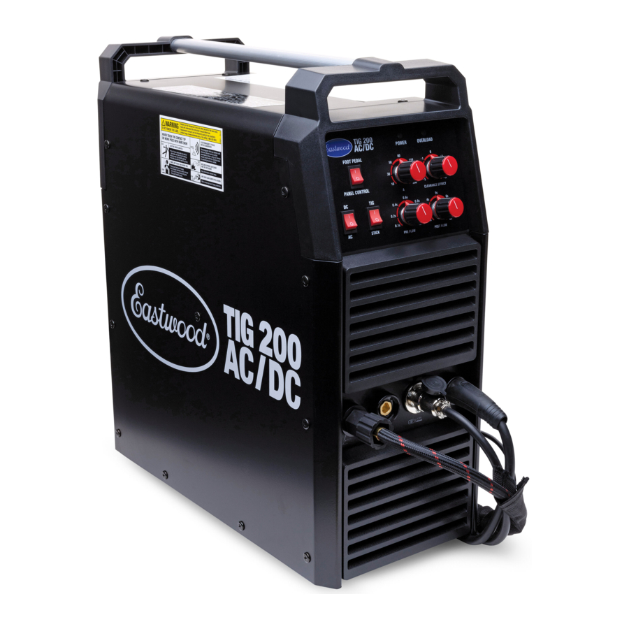
The EASTWOOD TIG 200 AC/DC WELDER allows for a more controllable, efficient, and versatile method of welding many metals including steel, stainless steel, aluminum and more. Your Eastwood TIG 200 AC/DC Welder, with High-Frequency Inverter Technology, is capable of welding thin or heavy gauge steel and aluminum with precision and ease. The voltage-sensing circuitry automatically detects a 120 or 240 VAC power source and delivers from 10 up to 200 Amps of AC or DC current at super-high frequency. The included Foot Pedal and Flex Head TIG Torch provide the operator with the best ergonomics for precision welding capability. A high frequency start feature guarantees an instant arc strike with no tungsten contamination. The Stick Welding function, with the optionally available Stick Electrode Holder (#20517), extend the capabilities of the welder even further, all in a single, lightweight package.
READ AND UNDERSTAND ALL INSTRUCTIONS AND PRECAUTIONS BEFORE PROCEEDING.
This unit emits a powerful high voltage and extreme heat which can cause severe burns, electrical shock, and death.
CONTENTS
COMPONENTS

(1) TIG 200 AC/DC Welder [A]
(1) Flex Head TIG Torch/12 ft. [3.6m]
Cable Assembly with #8 Gas Lens,
3/32" Collet, Long Back Cap and Collet Body Installed [B]
(1) 9.8 ft. [3m] Ground Cable/Clamp Assembly [C]
(1) Argon Regulator/Flowmeter [D]
(1) 4.6 ft. [1.4m] Shielding Gas Hose [E]
(1) 2ft. [0.6m] 240V NEMA 6-50R to 120V NEMA 5-15P Adapter Cord [F]
(1) Foot pedal, 16ft. [4.9m] Cable Assembly [G]
ACCESSORIES

(1) Handheld Welding Face Shield [H]
(1) Shield Lens [J]
(1) Shield Handle [K]
(1) Shield Handle Retaining Plug [L]
(1) Hammer Brush [M]
(1) Spare #8 Gas Lens [N]
(1) 1/16" Collet [P]
(1) 3/32" x 6" Tungsten, Green [Q]
(1) 3/32" x 6" Tungsten, Red [R]
(1) Collet Body, with Diffuser [S]
SPECIFICATIONS
POWER SUPPLY
| Power voltage (V) | 1 phase, 120 VAC/240 VAC, 50/60 Hz |
| Maximum Output No Load Voltage (V) | 62V DC |
| Rated Input Current: TIG (Amps) | 120V: 20 Amps 240V: 23.9 Amps |
| Rated Input Current: Stick (Amps) | 120V: 19.2 Amps 240V: 36.2 Amps |
| Output Current Range: TIG (Amps) | 120V: 10 TO 145 AMPS 240V: 10 TO 190 AMPS |
| Output Current Range: Stick (Amps) | 120V: 10 TO 140 AMPS 240V: 10 TO 185 AMPS |
| Duty cycle (%), TIG 120V | 60% @ 100 Amps 100% @ 77 Amps |
| Duty cycle (%), Stick 120V | 60% @ 60 Amps 100% @ 46 Amps 60% @ 190 Amps |
| Duty cycle (%), TIG 240V | 60% @ 190 Amps 100% @ 147 Amps |
| Duty cycle (%), Stick 240V | 60% @ 185 Amps 100% @ 143 Amps |
| Pre Gas Flow (Sec) | 0.1 - 1.0 SEC |
| Post Gas Flow (Sec) | 2 - 8 SEC |
| Maximum Material Thickness | 3/8" |
| Weight | 38.6 LBS. [17.5KG] |
| Dimensions | 17.8" X 8.4" X 20.2" [452MM X 213MM X 513MM] |
DUTY CYCLE
The rated Duty cycle refers to the amount of welding that can be done within an amount of time. It is easiest to look at your welding time in blocks of 10 Minutes and the Duty Cycle being a percentage of that 10 Minutes. If welding at 190 Amps with a 60% Duty Cycle, within a 10 Minute block of time you can weld for 6 Minutes with 4 Minutes of cooling for the Welder.
If the Duty Cycle is exceeded, and the built-in Breaker is tripped, allow the unit to cool for a minimum of 15 minutes. When a safe temperature has been reached, the Welder can be switched back on. To increase the duty cycle, turn down the Voltage Output control. Going above 190 Amps will yield a lower Duty Cycle.
SAFETY INFORMATION

These instructions are intended only to provide the user with some familiarity of the Eastwood TIG 200 AC/DC. Electric Welding is a highly complex procedure with many variables. If you have no prior experience with Electric Welding, it is extremely important to seek the advice of someone experienced in Electric Welding for instruction, enroll in a local technical school welding course or study a comprehensive how-to DVD and obtain a good quality reference book on Electric Welding as there is a moderate learning curve necessary before achieving proficiency in Welding different metals such as steel, stainless steel and aluminum. It is also strongly recommended that the user adhere to the American Welding Society guidelines, codes, and applications prior to producing welds where safety is affected.
Welding can be dangerous to you and other persons in the work area. Read and understand this instruction manual before using this Eastwood welding machine. Injury or death can occur if safe welding practices are not followed. Safety information is set forth below and throughout this manual. Save these instructions for future reference.
To learn more about welding safety, read OSHA Title 29 CFR 1910, available at www.osha.gov; ANSI Z49.1, "Safety in Welding, Cutting and Allied Processes," available at www.aws.org; and the consumable manufacturer's Safety Data Sheets.
The following explanations are displayed in this manual, on the labeling, and all other information provided with this product:

indicates a hazardous situation which, if not avoided, will result in death or serious injury.

indicates a hazardous situation which, if not avoided, could result in death or serious injury.

indicates a hazardous situation which, if not avoided, could result in minor or moderate injury.
NOTICE is used to address practices not related to personal injury.

ELECTRIC SHOCK CAN CAUSE INJURY OR DEATH!

- Improper use of an electric Welder can cause electric shock, injury, and death! Read all precautions described in the Welder Manual to reduce the possibility of electric shock.
- Disconnect Welder from power supply before assembly, disassembly, or maintenance of the TIG Torch and when installing or
- Always wear dry, protective clothing and leather welding gloves and insulated footwear. Use suitable clothing made from durable flame-resistant material to protect your skin.
- If other persons or pets are in the area of welding, use welding screens to protect bystanders from sparks.
- Always operate the Welder in a clean, dry, well ventilated area. Do not operate the Welder in humid, wet, rainy or poorly ventilated areas.
- The electrode and work (or ground) circuits are electrically "hot" when the Welder is on. Do not allow these "hot" parts to come in contact with bare skin or wet clothing.
- Stay separated from the welding circuit by using insulating mats to prevent contact from the work surface.
- Be sure that the work piece is properly supported and grounded prior to beginning an electric welding operation.
- Always attach the Ground Clamp to the piece to be welded and as close to the weld area as possible. This will give the least resistance and best weld.
WELDING SPARKS CAN CAUSE FIRE OR EXPLOSION!

- Electric welding produces sparks which can be discharged considerable distances at high velocity igniting flammable or exploding vapors and materials.
DO NOT operate electric arc Welder in areas where flammable or explosive vapors are present.
DO NOT use near combustible surfaces. Remove all flammable items from the work area where welding sparks can reach (minimum of 35 feet). - Always keep a fire extinguisher nearby while welding.
- Use welding blankets to protect painted and or flammable surfaces, rubber weather-stripping, dash boards, engines, etc.

ELECTROMAGNETIC FIELDS CAN BE A HEALTH HAZARD!

- The electromagnetic field that is generated during arc welding may interfere with various electrical and electronic devices such as cardiac pacemakers. Anyone using such devices should consult with their physician prior to performing any electric welding operations.
- Exposure to electromagnetic fields while welding may have other health effects which are not known.
ARC RAYS CAN INJURE EYES AND BURN!

- Arc rays produce intense ultraviolet radiation which can burn exposed skin and cause eye damage. Use a shield with the proper filter (a minimum of #11) to protect your eyes from sparks and the rays of the arc when welding or when observing open arc welding (see ANSI Z49.1 and Z87.1 for safety standards).
- Use suitable clothing made from durable flame-resistant material for skin protection.
- If other persons or pets are in the area of welding, use welding screens to protect bystanders from sparks and arc rays.
FUMES AND WELDING GASES CAN BE A HEALTH HAZARD!

- Fumes and gasses released during welding are hazardous. Do not breathe fumes that are produced by the welding operation.
- Prolonged inhalation of welding fumes above safety exposure limits can injure the lungs and other organs.
- Use enough ventilation and/or exhaust at the arc to keep fumes and gases from your breathing area.
- Use an OSHA approved respirator when welding in confined spaces or where there is inadequate ventilation.
- Never weld coated materials including but not limited to: cadmium plated, galvanized, lead based paints.
BUILDUP OF GAS CAN INJURE OR KILL!

- Shut off gas supply when not in use.
- Ensure adequate ventilation
- Do not weld in confined areas.
- Always turn your face away from valve outlet when opening cylinder valve.
CYLINDERS CAN EXPLODE IF DAMAGED!

Shielding gas cylinders contain gas under high pressure. If damaged, a cylinder can explode. As gas cylinders are a normal component of the welding process, use extra care to handle them carefully.
- Protect compressed gas cylinders from excessive heat, mechanical shocks, physical damage, slag, open flames, sparks, and arcs. Keep away from any welding or other electrical circuits.
- Install cylinders in an upright position by securing to a specifically designed rack, cart, or stationary support to prevent falling or tipping over.
- Never weld on a pressurized cylinder or explosion will occur.
- Use only correct shielding gas cylinders, regulators, hoses, and fittings designed for the specific application; maintain them and all related components in good condition.
- Keep protective cap in place over valve except when cylinder is in use.
- Use proper equipment, procedures and have adequate help when moving or lifting cylinders.
HOT METAL AND TOOLS WILL BURN!!

- Electric welding heats metal and tools to temperatures that will cause severe burns!
- Use protective, heat resistant gloves and clothing when using Eastwood or any other welding equipment. Never touch welded work surface, TIG Torch or nozzle until they have completely cooled.
FLYING METAL CHIPS CAN CAUSE INJURY!

- Grinding and sanding will eject metal chips, dust, debris, and sparks at high velocity. To prevent eye injury wear approved safety glasses.
- Wear an OSHA-approved respirator when grinding or sanding.
- Read all manuals included with specific grinders, sanders or other power tools used before and after the welding process. Be aware of all power tool safety warnings.

FIRST AID

- If exposed to excessive fumes move to an area with fresh air. Follow safety information on wire manufacturer's Safety Data Sheet.
- For other injuries follow basic first aid techniques and call physician or emergency medical personnel.
CONNECTING THE WELDER TO A POWER SOURCE
The Eastwood TIG 200 AC/DC Welder requires a dedicated 240 VAC, 50 AMP, circuit breaker protected outlet. The plug installed on the Welder is a NEMA 6-50P and should be used with a NEMA 6-50R receptacle.
As an alternative, by using the included Adapter Cord, the TIG 200 AC/DC can be used with a 120 VAC, 20 AMP, 60HZ grounded NEMA 5-15R outlet protected by a circuit breaker.
If using an extension cord, we recommend using our Welder Extension Cords for optimal performance: Eastwood items #31739, #20029, and #20285.
CONTROL AND DISPLAY PANEL
FRONT UPPER PANEL (FIG 1)

- Amperage Control: (A) 10 to 200 Amps
- Clearance Effect Control: -5 to +5
- Pre-Flow Control: (in seconds) 0.1s to 1s
- Post Flow Control: (in seconds) 2s to 8s
- Foot Pedal/Panel Control Selector: (Press the rocker switch to Select)
- Up = Foot pedal control, for use with foot pedal
- Down = Panel only control, for torch only use
- AC/DC Selector: (Press the rocker switch to Select)
- Up = DC output mode, typical for welding steels
- Down = AC output mode, typical for welding aluminum
- TIG/Stick Selector: (Press the rocker switch to Select)
- Up = TIG mode, for use with TIG torch
- Down = Stick mode, for use with stick welding electrode and electrode holder (Optional Eastwood #20517)
- Overload Indicator: Illuminates AMBER when the Duty Cycle has been exceeded, the Welder is overloaded or if other abnormalities exist
- Power ON Indicator: Illuminates GREEN when the ON/OFF Switch is ON
FRONT LOWER PANEL (FIG 2)

- TIG Torch Connection
- Electrode Holder Connection
- TIG Trigger and Foot Pedal Connection
- Ground Connection
REAR PANEL (FIG 3)

- 240 VAC Power Cord
- Shielding Gas Connection
- ON/OFF Switch
TIG 200 AC/DC WELDER SET-UP
The Eastwood TIG 200 AC/DC is factory set-up for TIG Welding use with a 3/32" Tungsten (Included) and 100% Argon Shielding Gas (Not Included).
The procedure for configuring to Stick welding use is covered further on in this Manual.
ASSEMBLE THE FACE SHIELD

- Slide the #11 Glass Shade [G] Lens under the Retaining Clips at the inside of the Shield [F] (FIG 4).
- Snap the Handle [H] into its receptacle from the Back of the shield seating it fully and firmly (FIG 4).
- Press the Handle Retaining Plug [J] into the corresponding shape from the front (FIG 5).


INSTALLING THE TIG TORCH

- Thread the Gas/Power Connector onto the receptacle and tighten firmly (FIG 6).
- Plug the Torch Trigger wire connection into the receptacle and rotate the collar to lock it in place (FIG 6).
- Switch the Foot Pedal/Panel Control Selector to the lower Panel Control position, and the TIG/Stick Selector to the upper TIG position (FIG 1).
IMPORTANT NOTE: The connection of the TIG Torch Hose/Wire Cable [B] MUST BE fully threaded and secured in the Gas/Power Connection Socket or gas may leak.
INSTALLING THE GROUND CABLE AND CLAMP
- Locate the 15 ft. Ground Cable/Clamp Assembly [C] and connect the plug on the brass end to the Negative Ground Cable Connection (–) on the Welder [c]. Align the key of the brass ferrule with the notch of the receptacle at the 12:00 position, insert the plug and twist Clockwise 1/2 turn until it is tight (FIG 6).
INSTALLING THE FOOT PEDAL
- Unlock and remove the Torch Trigger wire connection from the receptacle.
- Plug the Foot Pedal wire connection into the receptacle and rotate the collar to lock it in place (FIG. 7).

- Switch the Foot Pedal/Panel Control Selector to the upper Foot Pedal position (FIG 1).

INSTALLING THE SHIELDING GAS SUPPLY
NOTE: The following steps cover the installation of the Shielding Gas Valves, Hose and Tank (not included). See "Shielding Gas Flow Adjustment" under: "PREPARING TO TIG WELD".
BUILDUP OF GAS CAN INJURE OR KILL!
- Shut off shielding gas supply when not in use.
- Always ventilate confined spaces or use approved air-supplied respirator.
- Always turn your face away from valve outlet when opening cylinder valve.
CYLINDERS CAN EXPLODE IF DAMAGED!
Shielding gas cylinders contain gas under high pressure. If damaged, a cylinder can explode. As gas cylinders are a normal component of the welding process, use extra care to handle them carefully.
- Protect compressed gas cylinders from excessive heat, mechanical shocks, physical damage, slag, open flames, sparks, and arcs. Keep away from any welding or other electrical circuits.
- Install cylinders in an upright position by securing to a specifically designed rack, cart, or stationary support to prevent falling or tipping over.
- Never weld on a pressurized cylinder or explosion will occur.
- Use only correct shielding gas cylinders, regulators, hoses, and fittings designed for the specific application; maintain them and all related components in good condition.
- Keep protective cap in place over valve except when cylinder is in use.
- Use proper equipment, procedures and have adequate help when moving or lifting cylinders.
A Shielding Gas Bottle is NOT INCLUDED with the Eastwood TIG 200 AC/DC but is necessary to weld using the TIG torch. It can be bought at most local Welding Supply Stores. Eastwood recommends the use of 100% Argon for all TIG welding applications.
- Place the Eastwood TIG 200 AC/DC in a secure dedicated area or on a welding cart (not included).
- Secure the Shielding Gas Bottle to a stationary object or mount to a specifically designed welding cart, equipped to hold one so that the cylinder cannot fall over.
- Remove the cap from the Shielding Gas Bottle.
- Insert the large male fitting on the Argon Regulator/Flowmeter [D] into the female fitting on the Shielding Gas Bottle (not included).
![]()
Do not use White Thread Sealing Tape on this connection as it is an inert spherical gas fitting and does not require it, if you have a leak check for burrs or dirt in the threads or on the spherical joint. - Tighten the fitting with a wrench until snug, do not over tighten (FIG 8).

- Connect either end of the Shielding Gas Line [E] included with the Eastwood TIG 200 AC/DC to the fitting on the Regulator and wrench tighten until snug. (FIG 8).
- Connect the other end of the gas line to the fitting on the rear of the Eastwood TIG 200 AC/DC and wrench tighten until snug (FIG 3).
- Check the gas line for leaks by slowly opening the valve on the gas bottle. When welding the valve on the bottle should always be fully open. Close it when done welding to avoid loss of gas.

PREPARING TO TIG WELD
TORCH DISASSEMBLY
- The Welder MUST be turned off and unplugged.
- Remove the back cap from the torch.
- If there is a tungsten installed in the torch, pull it out from the front of the torch.
- Slide the collet out of the torch rear.
- Unscrew and remove the gas nozzle.
- Unscrew and remove the collet body (FIG 9).


TORCH ASSEMBLY
- Select the collet body that matches the intended tungsten diameter and thread it back into the front of the torch.
- Select a collet that matches the intended tungsten diameter. Insert the tungsten into the collet and put the collet and tungsten back into the torch.
- The Gas Nozzle size should be selected according to shielding gas requirements for the material being welded. This size can be referenced on the suggested settings chart. Select the correct gas nozzle and thread it onto the collet body.
- Reinstall the back cap to lock the tungsten in place. Always make sure the tungsten protrudes 1/8" to 1/4" beyond the gas nozzle.
SHARPENING THE TUNGSTEN
To avoid contamination of the Tungsten and ultimately the weld, it is imperative to have a dedicated grinding wheel used for Tungsten grinding only. A fine grit standard 6" synthetic stone grinding wheel on a bench top grinder is sufficient, or a dedicated tungsten grinder (Eastwood #21525) is optionally available.
- Shut off the welder.
- Make sure the Tungsten and Torch are sufficiently cooled for handling, then loosen and remove the Back Cap then the Collet and remove the Tungsten from the FRONT of the Torch only (removing from the rear will damage the Collet).
- If the Tungsten is used and the end is contaminated, use pliers or a suitable tool to grip the tungsten above the contaminated section and snap off the end of the Tungsten.
- Holding the Tungsten tangent to the surface of the grinding wheel, rotate the Tungsten while exerting light pressure until a suitable point is formed (FIGS 10 & 11).

- The ideal tip will have the length of the conical portion of the sharpened area at 2-1/2 times the Tungsten rod diameter (FIG 12).

- Replace the Tungsten in the Collet with the tip extending 1/8"-1/4" beyond the Gas Nozzle, then re-tighten the Back Cap.


SETTING SELECTION
- AC/DC – The type of current will need to be selected depending on the type of material being welded. For the most part when welding steels the switch will be set to DC and when welding aluminum the switch will be set to AC.
- Clearance Effect – This setting can be ignored if welding in DC. If welding in AC this will need to be set. The more negative the value will result in greater penetration and less cleaning and the more positive the value will result in less penetration but greater cleaning. For suggested settings refer to the data chart on the welder.
- Foot Pedal/Panel Control – Determine whether you will be using the switch on the torch or the foot pedal for arc starting and stopping and put the selector switch in the appropriate position. Note that some connections changes will be necessary also when switching the control type. These connection changes are covered in the Set-Up section of this manual.
- Amperage – Set the Output Amperage Knob marked "A" (FIG 1) located at upper left of the top panel to an appropriate setting based on the thickness and type of the metal being welded (refer to Data Chart for actual settings).
- Pre Flow – This adjustment controls the time (in seconds) that the shielding gas starts to flow before the arc starts (refer to Data Chart for actual settings).
- Post Flow – This adjustment controls the time (in seconds) that the shielding gas flows after the arc stops (refer to Data Chart for actual settings).
SHIELDING GAS FLOW ADJUSTMENT
After connecting the Argon Regulator/Flowmeter, the gas flow rate needs to be adjusted so that the proper amount of Shielding Gas is flowing over the weld. If there is too little gas flow, there will be porosity in the resulting welds as well as excessive spatter.
If there is too much gas flow, this will be wasting gas and may affect the weld quality. The included Regulator has 2 indicators on it; the gauge on the right is Tank Pressure while the indicator on the left is Gas Flow.
- Open the Shielding Gas tank valve all the way.
- After the Welder is turned on (Described in following section), the Trigger of the TIG Torch or Foot Pedal will control the internal gas flow.
- As the unit is triggered, the Gas Flow indicator ball will rise to a steady reading. This is the value to be used for measuring Gas Flow.
- The Gas Flow should ideally be set to ~20 SCFH while flowing. The SCFH (Standard Cubic Feet per Hour) scale is to the left of the pressure gauge, as the gas flows it will cause the ball to rise and the SCFH can be read from the scale. 20 SCFH is the most typical flow rate but it may need to be adjusted in some cases depending if there is a slight breeze or some other instance where additional shielding gas is required to prevent porosity in the weld.
- When finished welding, the Valve on the Gas Bottle must be closed.
OPERATING THE TIG 200 AC/DC WELDER
OVERLOAD PROTECTION
The Eastwood TIG 200 AC/DC Welder is equipped with an overload protection. This device will protect the Welder if the duty cycle is exceeded. If the output is exceeded, the breaker will trip, the AMBER Overload Indicator will illuminate and cut off the power supply to the TIG Torch although the fan will still run to cool the unit. This protection circuit must be reset manually by switching the unit back ON. Before restarting the unit allow the Welder to cool for a minimum of 15 minutes or until the AMBER Overload Indicator goes out.
These instructions are intended only to provide the user with some familiarity of the Eastwood TIG 200 AC/ DC. TIG welding is a highly complex procedure with many variables. If you have no experience with TIG welding; it is extremely important to seek the advice of someone experienced in TIG welding for instruction, enroll in a local technical school welding course or study a comprehensive how-to DVD and obtain a good quality reference book on TIG welding as there is a moderate learning curve necessary before achieving proficiency in TIG Welding. Before attempting to use this unit on an actual project or object of value, practice on a similar material as there are many variables present and settings required when TIG welding different metals such as steel or aluminum. It is also strongly recommended that the user adhere to the American Welding Society guidelines, codes, and applications prior to producing welds where safety is affected.
ELECTRIC SHOCK CAN CAUSE INJURY OR DEATH!
- Improper use of an electric Welder can cause electric shock, injury, and death! Read all precautions described in the Welder Manual to reduce the possibility of electric shock.
- Disconnect Welder from power supply before assembly, disassembly, or maintenance of the TIG Torch and when installing or removing nozzles.
- Always wear dry, protective clothing and leather welding gloves and insulated footwear. Use suitable clothing made from durable flame-resistant material to protect your skin.
- Always operate the Welder in a clean, dry, well ventilated area. Do not operate the Welder in humid, wet, rainy, or poorly ventilated areas.
- The electrode and work (or ground) circuits are electrically "hot" when the Welder is on.
- DO NOT allow these "hot" parts to come in contact with bare skin or wet clothing.
- Separate yourself from the welding circuit by using insulating mats to prevent contact from the work surface.
- Be sure that the work piece is properly supported and grounded prior to beginning an electric welding operation.
- Always attach the ground clamp to the piece to be welded and as close to the weld area as possible. This will give the least resistance and best weld.
WELDING SPARKS CAN CAUSE FIRE OR EXPLOSION!
- Electric welding produces sparks which can be discharged considerable distances at high velocity igniting flammable or exploding vapors and materials.
- Do not operate electric arc Welder in areas where flammable or explosive vapors are present.
- Do not use near combustible surfaces. Remove all flammable items within 35 feet of the welding area.
- Always keep a fire extinguisher nearby while welding.
- Use welding blankets to protect painted and or flammable surfaces, rubber weather-stripping, dash boards, engines, etc.
- If other persons or pets are in the area of welding, use welding screens to protect bystanders from sparks and UV radiation.
ELECTROMAGNETIC FIELDS CAN BE A HEALTH HAZARD!
- The electromagnetic field that is generated during arc welding may interfere with various electrical and electronic devices such as cardiac pacemakers. Anyone using such devices should consult with their physician prior to performing any electric welding operations.
- Exposure to electromagnetic fields while welding may have other health effects which are not known.
ARC RAYS CAN BURN!
- Arc rays produce intense ultraviolet radiation which can burn exposed skin and cause eye damage. Use a shield with the proper filter (a minimum of #11) to protect your eyes from sparks and the rays of the arc when welding or when observing open arc welding (see ANSI Z49.1 and Z87.1 for safety standards).
- Use suitable clothing made from durable flame-resistant material to protect your skin.
- If other persons or pets are in the area of welding, use welding screens to protect bystanders from sparks and arc rays.
FUMES AND WELDING GASES CAN BE A HEALTH HAZARD!
- Fumes and gasses released during welding are hazardous. Do not breathe fumes that are produced by the welding operation. Wear an OSHA-approved respirator when welding.
- Always work in a properly ventilated area.
- Never weld coated materials including but not limited to: cadmium plated, galvanized, lead based paints.
HOT METAL AND TOOLS WILL BURN!
- Electric welding heats metal and tools to temperatures that will cause severe burns!
- Use protective, heat resistant gloves and clothing when using Eastwood or any other welding equipment. Never touch welded work surface, TIG Torch or nozzle until they have completely cooled.
FLYING METAL CHIPS CAN CAUSE INJURY!
- Grinding and sanding will eject metal chips, dust, debris, and sparks at high velocity. To prevent eye injury wear approved safety glasses.
- Wear an OSHA-approved respirator when grinding or sanding.
- Read all manuals included with specific grinders, sanders or other power tools used before and after the welding process. Be aware of all power tool safety warnings.
TIG WELDING
- Turn the Power Switch/Circuit Breaker to the ON position.
- Slowly open the gas cylinder valve.
NOTE: Always open valve fully to avoid shielding gas leakage. - Depress gun trigger switch or foot pedal and adjust the flow regulator (refer to Data Chart for actual settings).
- Grounding is very important, place the Ground Cable Clamp on a clean, bare area of your work piece as close to the welding area as possible to minimize the chance of shock. Scrape, wire brush, file or grind a bare area to achieve a good ground to assure safety.
- Use a dedicated stainless-steel brush or flap-disc to clean the areas to be welded. This is particularly critical on aluminum as a microscopic layer of oxidation can prevent an arc and actually produce a poor-quality, contaminated weld.
Do not use the brush or flap-disc for any other purpose and keep one for steel and one for aluminum. - Make sure all your safety gear is in place (Welding Mask, Welding Gloves, Non-Flammable Long Sleeve Apparel) and the area is completely free of flammable material.
- Although it is a matter of developing a personal style, a good starting point for best results is achieved by holding the tip at a 75° angle. Hold the Filler Metal Rod at a 90° angle to the Tungsten Tip (FIG 13).

- Never allow the Tungsten Tip to touch the welding surface or material rod. Doing so will quickly destroy the tip and contaminate the weld. If this happens, remove the Tungsten, and regrind the tip. It is best to hold the Tungsten 1/8" from the surface.
- With a Welding Shield and all safety gear in place, depress the foot pedal or trigger and practice "Forming A Puddle" with the Tungsten Tip. Once you become familiar with this step, practice the "Dip and Pull" technique with the Filler Metal Rod and Torch. "Dip and Pull" is the practice of forming a puddle, moving the torch while maintaining the puddle and adding filler rod metal to the puddle by "dipping and pulling" as you go; being careful not to allow the Tungsten to contact the puddle or rod.
- Keep in mind that you MUST let the shielding gas flow over the weld after releasing the trigger or pedal. Failure to do so will allow the welded area to oxidize compromising the weld integrity.
- Constantly be aware that TIG welding quickly generates heat in the work piece and torch. Severe burns can quickly occur by contacting hot metal pieces.
- When done, shut off the Power Switch and close the Shielding Gas Tank valve completely.

STICK WELDING
With the optional #20517 Electrode Holder, the TIG 200 AC/DC can be used as a stick welding machine.
- Connect the electrode holder and configure the TIG/Stick switch down for stick welding (Fig 14).

- An Electrode can now be installed in the Electrode Holder, make sure the Electrode or "Stick" is not contacting the grounded workpiece.
- Switch the Power Switch to "ON".
- While wearing a properly functioning Auto Darkening Welding Helmet, lightly drag the tip of the Welding Rod along the workpiece surface to start an arc.
- Feed the Welding Rod into the workpiece joint at a 15° angle.
- Lift rod from workpiece when weld bead is completed.
- Turn off Welder power switch.
- Set the Electrode or "Stick" Holder on a safe, non-flammable, surface.

TORCH MAINTENANCE
The Eastwood TIG 200 AC/DC has several consumable parts that will need to be replaced over time. If wear or slag build up is noticed on any of the torch components, replace them immediately to avoid damage to the torch. Worn components will also contribute to poor performance. See the torch components (FIG 9) exploded view for a reference of all of the components and the assembly order.
TROUBLESHOOTING
| PROBLEM | CAUSE | CORRECTION |
Arc is Triggered but Will Not Start | Incomplete Circuit | Check Ground connection. Make sure that the ground is on a freshly cleaned surface and close to the welding area. It is suggested to weld towards the ground connection. |
| Incorrect Tungsten | Consult chart for proper tungsten for the base metal being welded. In most cases Thoriated will be used for all steels. | |
| No Shielding Gas | Make sure the shielding gas cylinder is turned all the way open and set at the correct flow rate. | |
| Wrong Polarity | Make sure polarity is set for the correct material. AC should be used for aluminum while DC should be used for steel. | |
| Arc Wanders and it is Hard to Concentrate Heat in a Specific Area | Poorly prepped tungsten | Follow guidelines for prepping tungsten. |
| Poor Gas Flow | Adjust the flow rate of the shielding gas (refer to settings chart). Check for loose fittings where gas could be leaking. | |
| Contaminated Tungsten | Remove tungsten from torch and break off contaminated section and resharpen. | |
| Incorrect arc length | Make sure the Tungsten is held 1/8 to 1/4 inch off the work piece. | |
| Incomplete circuit | Check Ground connection. Make sure that the ground is on a freshly cleaned surface and close to the welding area. It is suggested to weld towards the ground connection. | |
| Contaminated base metal | Clean base metal making sure to remove any oil, debris, coatings, or moisture. If base metal is aluminum, make sure all of the oxide is removed using either a dedicated stainless brush or flap wheel. | |
| Incorrect Clearance Effect (AC) | Shift more negative clearance on the Clearance Effect knob so less heat is going into the tungsten. | |
Porosity in Weld Bead | Poor Gas Flow | Adjust the flow rate of the shielding gas (refer to settings chart). Check for loose fittings where gas could be leaking. |
| Contaminated filler metal | Clean filler metal making sure to remove any oil, debris, or moisture. | |
| Contaminated base metal | Clean base metal making sure to remove any oil, debris, coatings, or moisture. | |
| Poor Shielding | Make sure to be in an area with no wind and with any fans turned off. Wind or fans will blow the shielding gas away from the weld causing porosity. | |
| Incorrect Tungsten Stick Out | Adjust the tungsten so that 1/8 to ¼ inch is sticking out of the collet. | |
Contamination in Weld Bead | Contaminated Tungsten | Remove tungsten from torch and break off contaminated section and resharpen. |
| Contaminated Filler Metal | Clean filler metal making sure to remove any oil, debris, or moisture. | |
| Contaminated Base Metal | Clean base metal making sure to remove any oil, debris, coatings, or moisture. If base metal is cold rolled steel, make sure to remove any mill scale. | |
Melting Tungsten | Poor Gas Flow | Adjust the flow rate of the shielding gas (refer to settings chart). Check for loose fittings where gas could be leaking. |
| Incorrect Clearance Effect (AC) | Shift more negative clearance on the Clearance Effect knob so less heat is going into the tungsten. | |
| Wrong Size Tungsten | Increase tungsten diameter. Refer to chart for proper sizing. | |
| Incorrect Shielding Gas | Only use 100% Argon when TIG Welding. | |
Poor Penetration (Aluminum) | Low Amperage | Amperage setting is too low for material/thickness. Increase as needed and reference chart on welder. |
| Incorrect Clearance Effect (AC) | Shift more negative clearance on the Clearance Effect knob so more heat is going into the material. | |
Poor Penetration (Steel) | Low Amperage | Amperage setting is too low for material/thickness. Increase as needed and reference chart on welder. |
Tungsten Contaminated | Contact of Tungsten with Base Metal | Keep tungsten 1/8 to 1/4 inch from the base metal. If tungsten comes in contact break off end and resharpen immediately. |
Poor Weld Appearance | Incorrect Positioning | The angle between the filler material and torch must be less than 90 degrees otherwise the filler metal will prematurely melt and glob off causing poor weld appearance. |
Crater in the End of the Weld Bead | Insufficient Shielding | Keep the torch on the base metal while the post flow shielding gas flows to protect and cool the metal and tungsten. |
| Not Enough Filler Material | Reduce current with pedal and add more filler at end of weld. It may also be beneficial to back step to ensure no crater will form. | |
Weld Bead is Cracking | Too much heat in material | Reduce heat and allow more time between passes. |
| Base Metal is absorbing too much heat | Preheat base metal (consult welding codes for requirements) | |
| Incorrect Filler Wire | Use appropriate filler wire type and diameter for the joint being welded. | |
Material is Warping | Insufficient Clamping | Clamp work piece tightly and weld while clamps are in place. |
| Insufficient Tack Welds | Add more tack welds until rigidity and stiffness is developed. | |
| Too Much Heat in Material | To reduce heat, it is best to spread the welding out around the area. This can be done by using stitch welding techniques, alternating sides, and/or taking your time and allowing the pieces to cool between passes. |
Eastwood Technical Assistance: 800.343.9353 >> tech@eastwood.com
Documents / Resources
References
Download manual
Here you can download full pdf version of manual, it may contain additional safety instructions, warranty information, FCC rules, etc.
Advertisement
Thank you! Your question has been received!


Need Assistance?
Do you have a question about the TIG 200 that isn't answered in the manual? Leave your question here.