Eastwood TIG200 Instructions Manual
Ac/dc welder
Hide thumbs
Also See for TIG200:
- User manual ,
- Assembly & operating instructions (25 pages) ,
- Assembly and operating instructions manual (21 pages)
Advertisement
Advertisement
Table of Contents

Related Manuals for Eastwood TIG200


Summary of Contents for Eastwood TIG200
- Page 1 Item #20565 TIG200 AC/DC WELDER INSTRUCTIONS...
-
Page 2: Duty Cycle
DUTY CYCLE The Rated Duty Cycle refers to the amount of welding that can be done within an amount of time. The Eastwood TIG 200 has a duty cycle of 60% at 190 Amps. It is easiest to look at your welding time in blocks of 10 Minutes and the Duty Cycle being a percentage of that 10 Minutes. If welding at 190 Amps with a 60% Duty Cycle, within a 10 Minute block of time you can weld for 6 Minutes with 4 Minutes of cooling for the welder. -
Page 3: Safety Information
SAFETY INFORMATION DANGER indicates a hazardous situation which, if not avoided, will result in death or serious injury. WARNING indicates a hazardous situation which, if not avoided, could result in death or serious injury. CAUTION used with the safety alert symbol, indicates a hazardous situation which, if not avoided, could result in minor or moderate injury. NOTICE is used to address practices not related to personal injury. - Page 4 • Electric welding heats metal and tools to temperatures that will cause severe burns! • Use protective, heat resistant gloves and clothing when using Eastwood or any other welding equipment. Never touch welded work surface, torch tip or nozzle until they have completely cooled.
-
Page 5: Required Items
POWER REQUIREMENTS The Eastwood TIG 200 AC/DC is Voltage sensing; it will automatically operate on 110-120 VAC, 50/60 Hz., or 220-240 VAC, 50/60 Hz. Eastwood recommends at a minimum a properly grounded 110-120 VAC 50/60Hz., 20 Amp circuit or 220-240 VAC 50/60Hz., 30 Amp circuit. -
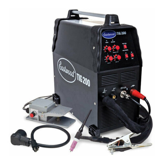
Page 6: Components And Controls
COMPONENTS AND CONTROLS FIG. A 1. Power Switch – The Power Switch also serves as the overload Circuit Breaker and is located at the right of the rear panel (FIG. C). 2. Amperage (Front Panel) – Set the Output Amperage Knob marked “A” (FIG. A), located at up- per left of the top panel, to an appropriate setting based on the thickness and type of the metal being welded. - Page 7 Shielding Gas Bottle (FIG. E). 5. Tighten the fi tting with a wrench till snug, do not over tighten. 6. Connect either end of the Gas Line included with your Eastwood TIG 200 to the fi tting on FIG. G the regulator and tighten with a wrench until snug.
- Page 8 PREPARING TO TIG WELD FIG. H Tungsten TORCH DISASSEMBLY ELECTRIC SHOCK CAN CAUSE INJURY OR DEATH! Disconnect Welder from power supply before assembly or disassembly of Torch and Cables. Gas Nozzle 1. Make sure the welder is turned off and unplugged. Collet Collet Body 2.
- Page 9 SETTINGS SELECTION With the materials selected of which you will be welding you can begin to set up the welder for the specific material. 1. AC/DC – The type of current will need to be selected depending on the type of material being welded. For the most part when welding steels the switch will be set to DC and when welding aluminum the switch will be set to AC.
-
Page 10: Tig Welding
TIG WELDING IMPORTANT NOTE: These instructions are intended only to provide the user with some familiarity of the Eastwood TIG 200. TIG welding is a highly complex proce- dure with many variables. If you have no experience with TIG welding; it is extremely important to seek the advice of someone experienced in TIG welding for instruc- tion, enroll in a local technical school welding course or study a comprehensive how-to DVD and obtain a good quality reference book on TIG welding as there is a moderate learning curve necessary before achieving proficiency in TIG Welding. - Page 11 1. Turn the Power Switch/Circuit Breaker to the on position. FIG. J 2. Slowly open the gas cylinder valve. NOTE: Always open valve fully to avoid shielding gas leakage. 3. Depress gun trigger switch or foot pedal and adjust the flow regulator. 90°...
-
Page 12: Torch Maintenance
The Eastwood TIG 200 has a number of consumable parts that will need to be replaced over time. If wear or slag build up is noticed on any of the torch compo- nents, replace them immediately to avoid damage to the torch. Worn components will also contribute to poor performance. See the torch components (FIG. H) -
Page 13: Tig Troubleshooting
Problem Cause Check G round c onnection. M ake s ure t hat t he g round i s o n a TIG TROUBLESHOOTING Problem Cause Incomplete C ircuit freshly ... - Page 14 TIG TROUBLESHOOTING...
-
Page 15: Stick Welding
Electric welding heats metal and tools to temperatures that will cause severe burns! Use protective, heat resistant gloves and clothing when using Eastwood or any other welding equipment. Never touch welded work surface, torch tip or nozzle until they have completely cooled. - Page 16 ACCESSORIES TIG WIRE & TUNGSTEN: #12253 ER70S-2 Steel TIG Wire 1/16-36” #12254 ER70S-2 Steel TIG Wire 3/32-36” #12375 4043 Aluminum TIG Wire 1/16-36” #12376 4043 Aluminum TIG Wire 3/32-36” #12463 308L Stainless TIG Wire 1/16-36” #12464 308L Stainless TIG Wire 3/32-36” #20176 E3 Purple Tungsten 1/16-7”...