Table of Contents
Advertisement
Quick Links
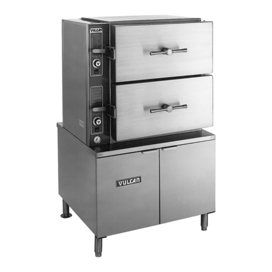
VL2GPS SHOWN
This Manual is prepared for the use of trained Vulcan Service
Technicians and should not be used by those not properly
qualified. If you have attended a Vulcan Service School for this
product, you may be qualified to perform all the procedures
described in this manual.
This manual is not intended to be all encompassing. If you have
not attended a Vulcan Service School for this product, you should
read, in its entirety, the repair procedure you wish to perform to
determine if you have the necessary tools, instruments and skills
required to perform the procedure. Procedures for which you do
not have the necessary tools, instruments and skills should be
performed by a trained Vulcan Service Technician.
Reproduction or other use of this Manual, without the express
written consent of Vulcan, is prohibited.
A product of VULCAN-HART
F24650 Rev. A (1017)
SERVICE MANUAL
VL BOILER BASE SERIES
CONVECTION STEAMERS
(GAS, ELECTRIC, DIRECT AND REGENERATED)
VL2GPS
ML-52391
VL2GMS
ML-52388
VL2GAS
ML-52390
VL2GSS
ML-52389
VL3GPS
ML-52395
VL3GMS
ML-52392
VL3GAS
ML-52394
VL3GSS
ML-52393
VL2EPS
ML-52741
VL2EMS
ML-52742
VL2EAS
ML-52743
VL2ESS
ML-52744
VL3EPS
ML-52745
VL3EMS
ML-52746
VL3EAS
ML-52747
VL3ESS
ML-52748
- NOTICE -
VL2DPS
ML-52749
VL2DMS
ML-52750
VL2DAS
ML-52751
VL2DSS
ML-52752
VL3DPS
ML-52753
VL3DMS
ML-52754
VL3DAS
ML-52755
VL3DSS
ML-52756
VL2RPS
ML-52757
VL2RMS
ML-52758
VL2RAS
ML-52759
VL2RSS
ML-52760
VL3RPS
ML-52761
VL3RMS
ML-52762
VL3RAS
ML-52763
VL3RSS
ML-52764
LOUISVILLE, KY 40201-0696
Advertisement
Table of Contents

Related Manuals for Vulcan-Hart VL Series


Summary of Contents for Vulcan-Hart VL Series
- Page 1 Vulcan Service Technician. Reproduction or other use of this Manual, without the express written consent of Vulcan, is prohibited. A product of VULCAN-HART LOUISVILLE, KY 40201-0696 F24650 Rev. A (1017)
- Page 2 VL BOILER BASE SERIES CONVECTION STEAMERS F24650 Rev. A (1017) Page 2 of 93 Text Text...
-
Page 3: Table Of Contents
VL BOILER BASE SERIES CONVECTION STEAMERS TABLE OF CONTENTS GENERAL ....................5 INTRODUCTION . - Page 4 VL BOILER BASE SERIES CONVECTION STEAMERS WIRING DIAGRAMS, ELECTRIC HEATER CIRCUITS VL2E AND VL3E - PREVENT, AUTOMATIC, STANDARD AND MANUAL ............81 SCHEMATIC AND WIRING DIAGRAMS, DIRECT STEAMERS, CABINET BASE VL2D AND VL3D - PREVENT, AUTOMATIC, STANDARD AND MANUAL .
-
Page 5: General
Reduction in heat transfer efficiency of the heating system. Boiler Code Descriptions Premature failure of electric heaters. Vulcan-Hart incorporates redundant controls in False readings by water level probes. compliance with California Code (Cal-Code) and Thermostat bulbs will sense temperature CSD-1 as an option on steam equipment when incorrectly. -
Page 6: Tools
VL BOILER BASE SERIES CONVECTION STEAMERS - GENERAL achieved by using a properly maintained water softener. Other chemical properties in water supplies can also affect good steam generation and vary from within each state and locality. The water level probes in the boiler use ions in the water to detect the water level. - Page 7 VL BOILER BASE SERIES CONVECTION STEAMERS - GENERAL Gas Steamers Electric Steamers AMPERAGE 1 PHASE 3 PHASE 3 PHASE - 4 WIRE TOTAL MODEL 208V 240V 208V 240V 480V 220/380V & 240/415V VL2EPS VL2EMS VL2ESS VL2EAS Page 7 of 93 F24650 Rev.
-
Page 8: Steamer Operation
VL BOILER BASE SERIES CONVECTION STEAMERS - GENERAL AMPERAGE 1 PHASE 3 PHASE 3 PHASE - 4 WIRE TOTAL MODEL 208V 240V 208V 240V 480V 220/380V & 240/415V *Standard On Models with Automatic Ignition - The knob on STEAMER OPERATION the gas combination control valve has two positions (On-Off) for control of main burners and Ensure that all utility connections to the steamer have... - Page 9 VL BOILER BASE SERIES CONVECTION STEAMERS - GENERAL water in the boiler. After approximately 15 minutes, Newer Models - Open the cabinet door and steam should be present for cooking product. Observe turn main power switch OFF. The switch's that the boiler pressure gauge indicates steam red light will go out, the blowdown/drain pressure of 9-11 psi for models with a pressure solenoid valve will be deenergized and the...
- Page 10 VL BOILER BASE SERIES CONVECTION STEAMERS - GENERAL equipped with a compartment pressure Approximately one minute before timer regulating valve. On models without the reaches zero, the steam control solenoid is compartment pressure regulating valve, the energized to unlatch the steam control arm. compartment pressure cycles with the boiler An internal spring will automatically pull the pressure between 4 and 6 psi.
-
Page 11: Component Function
VL BOILER BASE SERIES CONVECTION STEAMERS - GENERAL pressure regulating valve. On models compartment temperature reaches 180°F without the compartment pressure (the temperature at which preheating or regulating valve, the compartment pressure defrosting is complete) the red light will cycles with the boiler pressure between 4 to come on and the timer will start. - Page 12 VL BOILER BASE SERIES CONVECTION STEAMERS - GENERAL water level control works by using three different probe lengths to monitor the water level. The probes consist of a high level (HL), low level (LL) and low water cut-off (LLCO). Boiler Fill Solenoid Admits water to the boiler when demanded by the water level control to maintain the Valve .
- Page 13 VL BOILER BASE SERIES CONVECTION STEAMERS - GENERAL main valve coil upon a call for heat to supply gas to the main burners. The pilot and main solenoids are part of the gas combination control valve. (Gas models with electronic ignition.) Ignition Control Controls power to the ignition control module and allows a reset of the module if the gas...
- Page 14 VL BOILER BASE SERIES CONVECTION STEAMERS - GENERAL Steam Control Arm When energized, engages the lift arm (plunger) to raise the steam control arm off of the Solenoid ....catch, allowing it to return to its rear position.
-
Page 15: Removal And Replacement Of Parts
VL BOILER BASE SERIES CONVECTION STEAMERS - REMOVAL AND REPLACEMENT OF PARTS REMOVAL AND REPLACEMENT OF PARTS COMPONENT LOCATIONS Fig. 4 Page 15 of 93 F24650 Rev. A (1017) - Page 16 VL BOILER BASE SERIES CONVECTION STEAMERS - REMOVAL AND REPLACEMENT OF PARTS Fig. 5 F24650 Rev. A (1017) Page 16 of 93...
-
Page 17: Water Level Controls - Low Level Cut Off And Differential
VL BOILER BASE SERIES CONVECTION STEAMERS - REMOVAL AND REPLACEMENT OF PARTS Fig. 6 COOKING COMPARTMENT CONTROLS - COMPONENT CONFIGURATIONS Thermal switch, inlet steam gate valve, steam exhaust solenoid valve, steam control 1. Prevent (shown above) arm solenoid, timer, buzzer and power switch with light. Does not use a steam trap. Same as prevent except does not include steam exhaust solenoid valve but does include 2. -
Page 18: Cycling And High Limit Pressure Switches (Gas And Electric Models)
VL BOILER BASE SERIES CONVECTION STEAMERS - REMOVAL AND REPLACEMENT OF PARTS Slide the glass tube upwards until the bottom of BOILER ASSEMBLY the tube is clear of the fitting and lift it out. When reinstalling the tube use new sealing washers. -
Page 19: High Limit Thermostat
VL BOILER BASE SERIES CONVECTION STEAMERS - REMOVAL AND REPLACEMENT OF PARTS Open the cabinet base doors and remove the two HIGH LIMIT THERMOSTAT screws at the top of the boiler control box and allow cover to drop down. Both solenoid valves are located side by side near the front of the boiler control box with the boiler fill on the right and the cold water condenser to the left. -
Page 20: Gas Combination Control Valve
VL BOILER BASE SERIES CONVECTION STEAMERS - REMOVAL AND REPLACEMENT OF PARTS GAS COMBINATION CONTROL VALVE DISCONNECT THE ELECTRICAL POWER TO THE MACHINE AT THE MAIN CIRCUIT BOX. PLACE A TAG ON THE CIRCUIT BOX INDICATING THE CIRCUIT IS BEING SERVICED. Fig. -
Page 21: Heater Contactors
VL BOILER BASE SERIES CONVECTION STEAMERS - REMOVAL AND REPLACEMENT OF PARTS Turn screw handle fully counterclockwise and HEATER CONTACTORS remove from door. Remove screws mounting the pressure bar to the backside of the compartment door. NOTE: A compression spring is mounted behind each DISCONNECT THE ELECTRICAL screw. -
Page 22: Regenerated Steam Models (Steam Coil)
VL BOILER BASE SERIES CONVECTION STEAMERS - REMOVAL AND REPLACEMENT OF PARTS REGENERATED STEAM MODELS (STEAM COIL) DISCONNECT THE ELECTRICAL POWER TO THE MACHINE AT THE MAIN CIRCUIT BOX. PLACE A TAG ON THE CIRCUIT BOX INDICATING THE CIRCUIT IS BEING SERVICED. SHUT OFF THE STEAM SUPPLY BEFORE SERVICING THE UNIT. -
Page 23: Service Procedures And Adjustments
VL BOILER BASE SERIES CONVECTION STEAMERS - SERVICE PROCEDURES AND ADJUSTMENTS SERVICE PROCEDURES AND ADJUSTMENTS Check probe canister and float valve assembly BOILER (regenerated models) for a scale buildup and clean as necessary. Check drain hole for obstructions. Inspect the condition of the descalers as outlined CERTAIN PROCEDURES IN THIS in this section and replace if necessary. - Page 24 VL BOILER BASE SERIES CONVECTION STEAMERS - SERVICE PROCEDURES AND ADJUSTMENTS NOTE: If deliming solution accidently comes in contact with steamer components, lightly rinse off with clean water. Models with Blowdown Timer - Open the deliming assembly valve and pour the deliming solution into the port.
-
Page 25: Water Level Control(S) Test
VL BOILER BASE SERIES CONVECTION STEAMERS - SERVICE PROCEDURES AND ADJUSTMENTS To install a new descaler, stretch its wire coil so the If voltage is correct then the high level (HL) descaler hangs with its core completely below the relay should energize, closing HL-3 minimum water level in the boiler, but hanging free. - Page 26 VL BOILER BASE SERIES CONVECTION STEAMERS - SERVICE PROCEDURES AND ADJUSTMENTS After performing steps 1-5A and verifying the Turn the power switch OFF and disconnect the water level control boards operation, if the control lead wire from each probe. Note the location of is not functioning as described, then replace it the probes and the number of the wire connected and check for proper operation.
-
Page 27: Cycling And High Limit Pressure Switches (Gas And Electric Models)
VL BOILER BASE SERIES CONVECTION STEAMERS - SERVICE PROCEDURES AND ADJUSTMENTS Check through the probe socket opening in the Two slotted and square headed adjustment screws top of the canister assembly for the presence of extend through the top of the switch case. A pressure water. -
Page 28: Fill And Cold Water Solenoid Valves
VL BOILER BASE SERIES CONVECTION STEAMERS - SERVICE PROCEDURES AND ADJUSTMENTS NOTE: If internal solenoid parts appear to be FILL AND COLD WATER SOLENOID damaged or worn, then replace the solenoid valve. Do VALVES not reuse damaged or worn parts. No internal solenoid parts are available as a service replacement. -
Page 29: High Limit Thermostat
VL BOILER BASE SERIES CONVECTION STEAMERS - SERVICE PROCEDURES AND ADJUSTMENTS gauge sight glass, then check for a problem with the HIGH LIMIT THERMOSTAT boiler fill solenoid valve, water level control(s) or the water level probes. See WATER LEVEL CONTROL(S) TEST. Also, "water hammering" in the supply line, in conjunction with a check valve can cause a high water pressure pocket in the water line CERTAIN PROCEDURES IN THIS... -
Page 30: Boiler Blowdown Drain Solenoid Valve
VL BOILER BASE SERIES CONVECTION STEAMERS - SERVICE PROCEDURES AND ADJUSTMENTS the opening. If this symptom is suspect, remove the be thoroughly cleaned. See FILL AND COLD WATER solenoid as outlined in FILL AND COLD WATER SOLENOID VALVES for an inspection and cleaning SOLENOID VALVES. - Page 31 VL BOILER BASE SERIES CONVECTION STEAMERS - SERVICE PROCEDURES AND ADJUSTMENTS Gas combination control valve malfunction. NORMAL OPERATING STEAMER PRESSURES Check incoming and manifold gas (PSI) pressures as outlined in GAS MANIFOLD HIGH PRESSURE ADJUSTMENT. If pressure CYCLING CONTROL LIMIT VL MODEL adjustments are made and manifold TYPE...
-
Page 32: Inlet Water Strainer
VL BOILER BASE SERIES CONVECTION STEAMERS - SERVICE PROCEDURES AND ADJUSTMENTS Heavy scale buildup inside copper steam PILOT AND THERMOCOUPLE coil. ASSEMBLY (GAS MODELS) Building steam supply pressure low. Cooking compartment steam solenoid valve malfunction. INLET WATER STRAINER CERTAIN PROCEDURES IN THIS SECTION REQUIRES ELECTRICAL TEST OR MEASUREMENTS WHILE POWER IS APPLIED TO THE... - Page 33 VL BOILER BASE SERIES CONVECTION STEAMERS - SERVICE PROCEDURES AND ADJUSTMENTS NOTE: If adjustments in gas or pilot pressure settings If the pilot flame is correct and there are no drafts, then are made, always replace the adjustment cover screw the problem is in the thermocouple output voltage or to ensure proper gas control operation.
-
Page 34: Gas Burners
VL BOILER BASE SERIES CONVECTION STEAMERS - SERVICE PROCEDURES AND ADJUSTMENTS With the thermocouple disconnected, with lanced type ports and have adjustable air shutters connect the meter leads to the tube and in the front. Fixed orifice type hoods extend from the threaded end. -
Page 35: Automatic Ignition Systems (Gas Models)
VL BOILER BASE SERIES CONVECTION STEAMERS - SERVICE PROCEDURES AND ADJUSTMENTS AUTOMATIC IGNITION SYSTEMS (GAS MODELS) CERTAIN PROCEDURES IN THIS SECTION REQUIRES ELECTRICAL TEST OR MEASUREMENTS WHILE POWER IS APPLIED TO THE MACHINE. EXERCISE EXTREME CAUTION AT ALL TIMES. IF TEST POINTS ARE NOT EASILY ACCESSIBLE, DISCONNECT POWER, ATTACH TEST... - Page 36 VL BOILER BASE SERIES CONVECTION STEAMERS - SERVICE PROCEDURES AND ADJUSTMENTS Check to ensure that all electrical terminal If a spark from ignitor is present but connections on the ignition control module does not ignite gas before the ignition and the ignitor are clean and tight. If loose control module locks out, (90 sec.) connections are found, make the necessary there may not be enough gas in the line...
-
Page 37: Gas Manifold Pressure Adjustment
VL BOILER BASE SERIES CONVECTION STEAMERS - SERVICE PROCEDURES AND ADJUSTMENTS Remove the adjustment screw cap to access the GAS MANIFOLD PRESSURE pressure adjustment screw. ADJUSTMENT CERTAIN PROCEDURES IN THIS SECTION REQUIRES ELECTRICAL TEST OR MEASUREMENTS WHILE POWER IS APPLIED TO THE MACHINE. -
Page 38: Direct Steam Models
VL BOILER BASE SERIES CONVECTION STEAMERS - SERVICE PROCEDURES AND ADJUSTMENTS DIRECT STEAM MODELS SHUT OFF THE STEAM SUPPLY BEFORE SERVICING THE UNIT. To remove a steam coil, disconnect union in steam supply line to the coils and in the condensate CERTAIN PROCEDURES IN THIS discharge line from the coils. -
Page 39: Heating Elements
VL BOILER BASE SERIES CONVECTION STEAMERS - SERVICE PROCEDURES AND ADJUSTMENTS contactor if the electrical contacts appear to be If voltage is incorrect, find the source of the severely pitted or burned. problem. If voltage is correct, check current draw HEATING ELEMENTS (amps) through the heating element lead wires. -
Page 40: Thermal Switch - Prevent And Automatic Models
VL BOILER BASE SERIES CONVECTION STEAMERS - SERVICE PROCEDURES AND ADJUSTMENTS RESISTANCE AMPERAGE AMPERAGE NUMBER OF KW PER VOLTAGE TOTAL KW PER LINE: PER LINE: ELEMENTS ELEMENT ELEMENT (OHMS) 10.5 12.36 14.40 57.60 * 220/380 14.40 240/415 * Asterisk (*) indicates 3 phase/4 wire. NOTE: Values in the table are nominal. -
Page 41: Water Level Gauge Assembly
VL BOILER BASE SERIES CONVECTION STEAMERS - SERVICE PROCEDURES AND ADJUSTMENTS If the cooking cycle is started normally, but STEAM GATE VALVE(S) the red light and timer do not come on or an abnormal amount of time elapses before they come on, then the load compensator is set too high. - Page 42 VL BOILER BASE SERIES CONVECTION STEAMERS - SERVICE PROCEDURES AND ADJUSTMENTS inlet valve is open and the exhaust valve closed when the steam control arm handle is pulled forward and reverses when the control arm is released. NOTE: In the event of an electrical component or a power failure, the steam control arm can be operated manually on automatic models.
-
Page 43: Electrical Operation
VL BOILER BASE SERIES CONVECTION STEAMERS - ELECTRICAL OPERATION ELECTRICAL OPERATION contacts open, the boiler fill solenoid is de-energized, WATER LEVEL CONTROLS stopping the flow of water into the boiler. When the water level drops below the low level (LL) Solid State - Low Level Cut-Off &... - Page 44 VL BOILER BASE SERIES CONVECTION STEAMERS - ELECTRICAL OPERATION illuminates the LLCO LED. With the LLCO-2 contacts closed the auxiliary heating control is then energized. The LLCO relay will remain energized and its LED will stay lit until the water level in the boiler drops below the LLCO probe.
- Page 45 VL BOILER BASE SERIES CONVECTION STEAMERS - ELECTRICAL OPERATION side of the secondary winding, through the contactor coil, through the water level control probe, through the water in the boiler and to the boiler for ground. The other side of the transformer secondary is attached to ground.
-
Page 46: Sequence Of Operation
VL BOILER BASE SERIES CONVECTION STEAMERS - ELECTRICAL OPERATION Fig. 21 Electro Mechanical - Auxiliary Low Level Cut-Off energized until the water level in the boiler drops below the LLCO probe. This control serves as a safety backup to the main low level cut-off (LLCO) control to meet Cal-Code When the boiler stops filling, press the manual reset requirements. - Page 47 VL BOILER BASE SERIES CONVECTION STEAMERS - ELECTRICAL OPERATION CSD-1 (code) boiler controls option and with Prevent is pressed. The low water indicator light will remain on cooking compartment controls. Refer to schematic and the safety circuit de-energized until the water level diagram numbers 3928 and 3929 for a boiler control in the boiler reaches the low level cut-off probes schematic and 3962 for a schematic and wiring...
- Page 48 VL BOILER BASE SERIES CONVECTION STEAMERS - ELECTRICAL OPERATION LLCO relay energizes, LLCO-2 (N.O.) Auxiliary gas solenoid valve is energized contacts close and LED lights. and opens to allow gas flow. Power to terminal LLCO on the auxiliary low As long as the ignition control module is water level cut-off control.
- Page 49 VL BOILER BASE SERIES CONVECTION STEAMERS - ELECTRICAL OPERATION solenoid valves. The gas solenoid Micro switch SW2 contacts change state valves will remain off and the low water from N.O. back to N.C. (normal starting level light will come on and stay lit until position).
- Page 50 VL BOILER BASE SERIES CONVECTION STEAMERS - ELECTRICAL OPERATION HL relay is energized. Cooking timers off. Contacts HL-3 close. Compartment power switches OFF. HL LED comes on. Unit connected to correct voltage supply. Fill solenoid is energized and water L1 to one side of the boiler fill solenoid flows into tank.
- Page 51 VL BOILER BASE SERIES CONVECTION STEAMERS - ELECTRICAL OPERATION cut-off control, the low level cut-off control remains de- probe to keep the coil energized after the water level energized. The heating elements will not come on until drops below the high level probe. the manual rest switch is pressed these conditions are Boiler steam pressure reaches upper limit set satisfied.
- Page 52 VL BOILER BASE SERIES CONVECTION STEAMERS - ELECTRICAL OPERATION Compartment steam control arm is pulled Micro switch SW1 contacts change state forward and latches, allowing steam to enter from N.O. back to N.C. (normal starting compartment. position). NOTE: Cool air and condensate exit through the Buzzer is energized.
- Page 53 VL BOILER BASE SERIES CONVECTION STEAMERS - ELECTRICAL OPERATION NOTE: The internal contactor coil has a locking path Blowdown timer switch is pressed. through contacts on terminals 7 and 8 to the low level The normally open timer contacts close, probe to keep the coil energized after the water level energizing the blowdown solenoid valve and drops below the high level probe.
-
Page 54: Schematics, Gas Steamers, Boiler Controls Vl2G And Vl3G - Prevent, Automatic, Standard And Manual
VL BOILER BASE SERIES CONVECTION STEAMERS - ELECTRICAL OPERATION SCHEMATICS, GAS STEAMERS, BOILER CONTROLS VL2G AND VL3G - PREVENT, AUTOMATIC, STANDARD AND MANUAL Manual Ignition, Standard Controls Fig. 23 F24650 Rev. A (1017) Page 54 of 93... - Page 55 VL BOILER BASE SERIES CONVECTION STEAMERS - ELECTRICAL OPERATION Electronic Ignition, Standard Controls Fig. 24 Page 55 of 93 F24650 Rev. A (1017)
- Page 56 VL BOILER BASE SERIES CONVECTION STEAMERS - ELECTRICAL OPERATION Manual Ignition, CSD-1 Code Controls Fig. 25 F24650 Rev. A (1017) Page 56 of 93...
- Page 57 VL BOILER BASE SERIES CONVECTION STEAMERS - ELECTRICAL OPERATION Electronic Ignition, CSD-1 Code Controls Fig. 26 Page 57 of 93 F24650 Rev. A (1017)
- Page 58 VL BOILER BASE SERIES CONVECTION STEAMERS - ELECTRICAL OPERATION Fig. 27 F24650 Rev. A (1017) Page 58 of 93...
-
Page 59: Wiring Diagrams, Gas Steamers, Boiler Controls Vl2G And Vl3G - Prevent, Automatic, Standard And Manual
VL BOILER BASE SERIES CONVECTION STEAMERS - ELECTRICAL OPERATION WIRING DIAGRAMS, GAS STEAMERS, BOILER CONTROLS VL2G AND VL3G - PREVENT, AUTOMATIC, STANDARD AND MANUAL Manual Ignition, Standard Controls Fig. 28 Page 59 of 93 F24650 Rev. A (1017) - Page 60 VL BOILER BASE SERIES CONVECTION STEAMERS - ELECTRICAL OPERATION Fig. 29 F24650 Rev. A (1017) Page 60 of 93...
- Page 61 VL BOILER BASE SERIES CONVECTION STEAMERS - ELECTRICAL OPERATION Electronic Ignition, Standard Controls Fig. 30 Page 61 of 93 F24650 Rev. A (1017)
- Page 62 VL BOILER BASE SERIES CONVECTION STEAMERS - ELECTRICAL OPERATION Fig. 31 F24650 Rev. A (1017) Page 62 of 93...
- Page 63 VL BOILER BASE SERIES CONVECTION STEAMERS - ELECTRICAL OPERATION Manual Ignition, CSD-1 Code Controls Fig. 32 Page 63 of 93 F24650 Rev. A (1017)
- Page 64 VL BOILER BASE SERIES CONVECTION STEAMERS - ELECTRICAL OPERATION Fig. 33 F24650 Rev. A (1017) Page 64 of 93...
- Page 65 VL BOILER BASE SERIES CONVECTION STEAMERS - ELECTRICAL OPERATION Electronic Ignition, CSD-1 Code Controls Fig. 34 Page 65 of 93 F24650 Rev. A (1017)
- Page 66 VL BOILER BASE SERIES CONVECTION STEAMERS - ELECTRICAL OPERATION Fig. 35 F24650 Rev. A (1017) Page 66 of 93...
-
Page 67: Schematics, Electric Steamers, Boiler Controls Vl2E And Vl3E - Prevent, Automatic, Standard And Manual
VL BOILER BASE SERIES CONVECTION STEAMERS - ELECTRICAL OPERATION SCHEMATICS, ELECTRIC STEAMERS, BOILER CONTROLS VL2E AND VL3E - PREVENT, AUTOMATIC, STANDARD AND MANUAL Auto Blowdown, Standard Controls Fig. 36 Page 67 of 93 F24650 Rev. A (1017) - Page 68 VL BOILER BASE SERIES CONVECTION STEAMERS - ELECTRICAL OPERATION Auto Blowdown, Cal-Code Controls Fig. 37 F24650 Rev. A (1017) Page 68 of 93...
-
Page 69: Wiring Diagrams, Electric Steamers, Boiler Controls Vl2E And Vl3E - Prevent, Automatic, Standard And Manual
VL BOILER BASE SERIES CONVECTION STEAMERS - ELECTRICAL OPERATION WIRING DIAGRAMS, ELECTRIC STEAMERS, BOILER CONTROLS VL2E AND VL3E - PREVENT, AUTOMATIC, STANDARD AND MANUAL Auto Blowdown, Standard Controls (contactor - 1 std.) Fig. 38 Page 69 of 93 F24650 Rev. A (1017) - Page 70 VL BOILER BASE SERIES CONVECTION STEAMERS - ELECTRICAL OPERATION Fig. 39 F24650 Rev. A (1017) Page 70 of 93...
- Page 71 VL BOILER BASE SERIES CONVECTION STEAMERS - ELECTRICAL OPERATION Auto Blowdown, Standard Controls (contactors - 2 std.) Fig. 40 Page 71 of 93 F24650 Rev. A (1017)
- Page 72 VL BOILER BASE SERIES CONVECTION STEAMERS - ELECTRICAL OPERATION Fig. 41 F24650 Rev. A (1017) Page 72 of 93...
- Page 73 VL BOILER BASE SERIES CONVECTION STEAMERS - ELECTRICAL OPERATION Manual Blowdown, Cal-Code Controls (contactors - 1 std. 1 aux.) Fig. 42 Page 73 of 93 F24650 Rev. A (1017)
- Page 74 VL BOILER BASE SERIES CONVECTION STEAMERS - ELECTRICAL OPERATION Fig. 43 F24650 Rev. A (1017) Page 74 of 93...
- Page 75 VL BOILER BASE SERIES CONVECTION STEAMERS - ELECTRICAL OPERATION Auto Blowdown, Cal-Code Controls (contactors - 1 std. 1 aux.) Fig. 44 Page 75 of 93 F24650 Rev. A (1017)
- Page 76 VL BOILER BASE SERIES CONVECTION STEAMERS - ELECTRICAL OPERATION Fig. 45 F24650 Rev. A (1017) Page 76 of 93...
- Page 77 VL BOILER BASE SERIES CONVECTION STEAMERS - ELECTRICAL OPERATION Auto Blowdown, Cal-Code Controls (contactors - 2 std. 2 aux.) Fig. 46 Page 77 of 93 F24650 Rev. A (1017)
- Page 78 VL BOILER BASE SERIES CONVECTION STEAMERS - ELECTRICAL OPERATION Fig. 47 F24650 Rev. A (1017) Page 78 of 93...
- Page 79 VL BOILER BASE SERIES CONVECTION STEAMERS - ELECTRICAL OPERATION Manual Blowdown, Cal-Code Controls (contactors - 2 std. 2 aux.) Fig. 48 Page 79 of 93 F24650 Rev. A (1017)
- Page 80 VL BOILER BASE SERIES CONVECTION STEAMERS - ELECTRICAL OPERATION Fig. 49 F24650 Rev. A (1017) Page 80 of 93...
-
Page 81: Wiring Diagrams, Electric Heater Circuits Vl2E And Vl3E - Prevent
VL BOILER BASE SERIES CONVECTION STEAMERS - ELECTRICAL OPERATION WIRING DIAGRAMS, ELECTRIC HEATER CIRCUITS VL2E AND VL3E - PREVENT, AUTOMATIC, STANDARD AND MANUAL Standard and Cal-Code/CSD-1 Controls Fig. 50 Page 81 of 93 F24650 Rev. A (1017) -
Page 82: Schematic And Wiring Diagrams, Direct Steamers, Cabinet Base Vl2D And Vl3D - Prevent, Automatic, Standard And Manual
VL BOILER BASE SERIES CONVECTION STEAMERS - ELECTRICAL OPERATION SCHEMATIC AND WIRING DIAGRAMS, DIRECT STEAMERS, CABINET BASE VL2D AND VL3D - PREVENT, AUTOMATIC, STANDARD AND MANUAL See SCHEMATIC AND WIRING DIAGRAMS - COMPARTMENT CONTROLS F24650 Rev. A (1017) Page 82 of 93... -
Page 83: Wiring Diagrams, Regenerated Steamers, Boiler Controls Vl2R
VL BOILER BASE SERIES CONVECTION STEAMERS - ELECTRICAL OPERATION WIRING DIAGRAMS, REGENERATED STEAMERS, BOILER CONTROLS VL2R AND VL3R - PREVENT, AUTOMATIC, STANDARD AND MANUAL Manual Blowdown (Older Models) Fig. 51 Page 83 of 93 F24650 Rev. A (1017) - Page 84 VL BOILER BASE SERIES CONVECTION STEAMERS - ELECTRICAL OPERATION Auto Blowdown (Older Models) Fig. 52 F24650 Rev. A (1017) Page 84 of 93...
-
Page 85: Schematic And Wiring Diagrams - Compartment Controls
VL BOILER BASE SERIES CONVECTION STEAMERS - ELECTRICAL OPERATION SCHEMATIC AND WIRING DIAGRAMS - COMPARTMENT CONTROLS Prevent Fig. 53 Page 85 of 93 F24650 Rev. A (1017) - Page 86 VL BOILER BASE SERIES CONVECTION STEAMERS - ELECTRICAL OPERATION Automatic Fig. 54 F24650 Rev. A (1017) Page 86 of 93...
- Page 87 VL BOILER BASE SERIES CONVECTION STEAMERS - ELECTRICAL OPERATION Standard Fig. 55 Page 87 of 93 F24650 Rev. A (1017)
- Page 88 VL BOILER BASE SERIES CONVECTION STEAMERS - ELECTRICAL OPERATION Manual NO ELECTRICAL COMPONENTS ARE USED WITH THE MANUAL COMPARTMENT CONTROLS OPTION. THE CONTROLS CONSIST OF A MANUAL COOKING TIMER AND MANUAL STEAM CONTROL ARM TO CLOSE AND OPEN THE STEAM GATE VALVES. F24650 Rev.
-
Page 89: Troubleshooting
VL BOILER BASE SERIES CONVECTION STEAMERS - TROUBLESHOOTING TROUBLESHOOTING ALL MODELS SYMPTOM POSSIBLE CAUSES Drain screen clogged. Drain line obstructed or not to an open gap drain. Steamer not level. Excessive cooking compartment pressures. On models equipped with the compartment pressure regulating valve, verify the compartment pressure is 6 psi Compartment leaks water around door. - Page 90 VL BOILER BASE SERIES CONVECTION STEAMERS - TROUBLESHOOTING SYMPTOM POSSIBLE CAUSES Check incoming voltage. Boiler not filled - check fill solenoid for power, clogging or malfunction. Water Level Control malfunction. HL-3 relay not energizing or contacts not closing to power boiler fill solenoid. Water too “pure”...
- Page 91 VL BOILER BASE SERIES CONVECTION STEAMERS - TROUBLESHOOTING SYMPTOM POSSIBLE CAUSES Water supply not on or pressure too low. Line strainer clogged. Fill solenoid not malfunctioning or plugged. Boiler does not fill or slow to fill. A High pressure pocket in the supply line to the boiler causes the fill solenoid valve not to open.
-
Page 92: Gas Models Only
VL BOILER BASE SERIES CONVECTION STEAMERS - TROUBLESHOOTING SYMPTOM POSSIBLE CAUSES Steam control arm not returning after unlatching (automatic, standard and manual models). Broken or missing return spring. Cooking Compartment not venting at end of cook cycle (Prevent models) or when Packing nut on steam gate valve to tight. - Page 93 VL BOILER BASE SERIES CONVECTION STEAMERS - TROUBLESHOOTING SYMPTOM POSSIBLE CAUSES Gas not on. Pilot going out due to drafts, excess steam from drain or steamer not level. Improper venting can direct the pilot flame away from thermopile or flame sensor. Low incoming gas pressure.